UFS 1-UFS架构简介
- 1 UFS是什么?
- 1.1 UFS
- 1.2 一般特征
- 1.2.1 Target performance
- 1.2.2 Target host applications
- 1.2.3 Target device types
- 1.2.4 Topology
- 1.2.5 UFS Layering
- 1.3 Interface Features
- 1.3.1 Three power supplies
- 1.3.2 Signaling as defined by [MIPI-M-PHY]
- 1.3.3 8b10b line coding, as defined by MIPI M-PHY
- 1.3.4 High reliability – BER under 10-10
- 1.3.5 Two signaling schemes
- 1.3.6 Multiple gears defined for both Low-Speed and High-Speed mode
- 1.3.7 Adapt (M-PHY® version 4.1)
- 1.4 Functional Features
- 2 UFS 架构简介
- 2.1 UFS 顶层架构
- 2.1.1 应用层
- 2.1.2 UFS 设备管理器
- 2.1.3 Service Access Points(服务接入点)
- 2.1.4 UFS Transport Protocol Layer
- 2.1.5 UFS Interconnect Layer
- 2.2 UFS System Model
1 UFS是什么?
1.1 UFS
UFS:是Universal Flash Storage 缩写,通用闪存 (UFS) 是一种简单、高性能、具有串行接口的大容量存储设备。它主要用于移动系统,介于主机处理和大容量存储设备之间。
1.2 一般特征
1.2.1 Target performance
High speed GEARs
- Support for GEAR1 is mandatory
- Support for GEAR2 is mandatory
- Support for GEAR3 is mandatory
- Support for GEAR4 is mandatory
1.2.2 Target host applications
Mobile phone, UMPC, DSC, PMP, MP3 and any other applications that require mass storage,bootable mass storage, and external card.
手机、UMPC、DSC、PMP、MP3等任何需要大容量存储、可启动大容量存储和外接卡的应用程序。
1.2.3 Target device types
- External card
- Embedded device
- Mass storage and bootable mass storage
- Future expansion of device class types
- I/O devices, camera, wireless, … , etc.
1.2.4 Topology
One device per UFS port(每个 UFS 端口一个设备。).
1.2.5 UFS Layering
- UFS Command Set Layer (UCS)
- Simplified SCSI command set based on SBC and SPC. UFS will not modify these SBC and SPC Compliant commands. Option for defining UFS Native command and future extension exist.
- 基于 SBC 和 SPC 的简化 SCSI 命令集。 UFS 不会修改这些 SBC 和 SPC 兼容命令。存在用于定义 UFS Native 命令和未来扩展的选项。
- UFS Transport Protocol Layer (UTP)
- JEDEC to define the supported protocol layer, i.e., UTP for SCSI. This does not exclude the support of other protocol in UFS Transport Protocol Layer.
- JEDEC 定义支持的协议层,即 SCSI 的 UTP。这并不排除 UFS 传输协议层中其他协议的支持。
- UFS Interconnect Layer (UIC)
- MIPI UniPro® [MIPI-UniPro] is adopted for data link layer
- MIPI M-PHY® [MIPI-M-PHY ] is adopted for physical layer
1.3 Interface Features
1.3.1 Three power supplies
- VCCQ power supply: 1.2 V (nominal)
- VCCQ2 power supply: 1.8 V (nominal)
- VCC power supply: 2.5 V/3.3 V (nominal)
1.3.2 Signaling as defined by [MIPI-M-PHY]
- 400 mVp (not terminated)
- 200 mVp (terminated)
1.3.3 8b10b line coding, as defined by MIPI M-PHY
1.3.4 High reliability – BER under 10-10
1.3.5 Two signaling schemes
- Low-speed mode with PWM signaling scheme
- High-Speed burst mode
1.3.6 Multiple gears defined for both Low-Speed and High-Speed mode
1.3.7 Adapt (M-PHY® version 4.1)
M-RX equalizer training to adapt to the channel characteristic
1.4 Functional Features
UFS functional features are NAND management features. These include
UFS 功能特性是NAND 管理特性。这些包括:
- Similar functional features as eMMC
- Boot Operation Mode
- Multiple logical units with configurable characteristics
- Replay Protected Memory Block (RPMB)
- Reliable write operation
- Background operations
- Secure operations, Purge and Erase to enhance data security
- Write Protection options, including Permanent and Power-On Write Protection
- Signed access to a Replay Protected Memory Block
- HW Reset Signal
- Task management operations
- Power management operations
2 UFS 架构简介
2.1 UFS 顶层架构
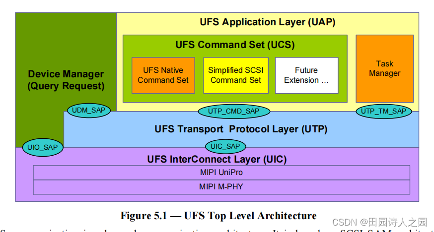
UFS communication is a layered communication architecture. It is based on SCSI SAM architectural model [SAM].
UFS通信是一种分层通信架构。它基于 SCSI SAM 体系结构模型 [SAM]。
2.1.1 应用层
The application layer consists of the UFS command set (UCS), the device manager and the Task Manager. The UCS will handle the normal commands like read, write, and so on. UFS may support multiple command sets. UFS is designed to be protocol agnostic. The command set for this version UFS standard is based on SCSI command set. In particular, a simplified SCSI command set was selected for UFS. UFS Native command set can be supported when it is needed to extend the UFS functionalities.
应用层由UFS命令集(UCS)、设备管理器和任务管理器组成。 UCS 将处理普通命令,如读、写等。 UFS 可能支持多个命令集。 UFS 被设计为与协议无关。该版本UFS标准的命令集是基于SCSI命令集的。特别是,为 UFS 选择了一个简化的 SCSI 命令集。当需要扩展 UFS 功能时,可以支持 UFS Native 命令集。
The Task Manager handles commands meant for command queue control. The Device Manager will provide device level control like Query Request and lower level link-layer control.
任务管理器处理用于命令队列控制的命令。设备管理器将提供设备级控制,如查询请求和较低级别的链路层控制。
2.1.2 UFS 设备管理器
The device manager has the following two responsibilities:
设备管理器有以下两个职责:
- Handling device level operations.
- 处理设备级操作。
- Managing device level configurations.
- 管理设备级配置。
Device level operations include functions such as device power management, settings related to data transfer, background operations enabling, and other device specific operations.
设备级操作包括设备电源管理、与数据传输相关的设置、后台操作启用和其他设备特定操作等功能。
Device level configuration is managed by the device manager by maintaining and storing a set of descriptors. The device manager handles commands like query request which allow to modify or retrieve configuration information of the device.
设备级配置由设备管理器通过维护和存储一组描述符来管理。设备管理器处理诸如查询请求之类的命令,这些命令允许修改或检索设备的配置信息。
2.1.3 Service Access Points(服务接入点)
As seen from the diagram the device manager interacts with lower layers using the following two service access points:
从图中可以看出,设备管理器使用以下两个服务访问点与较低层进行交互:
- UDM_SAP
- UIO_SAP
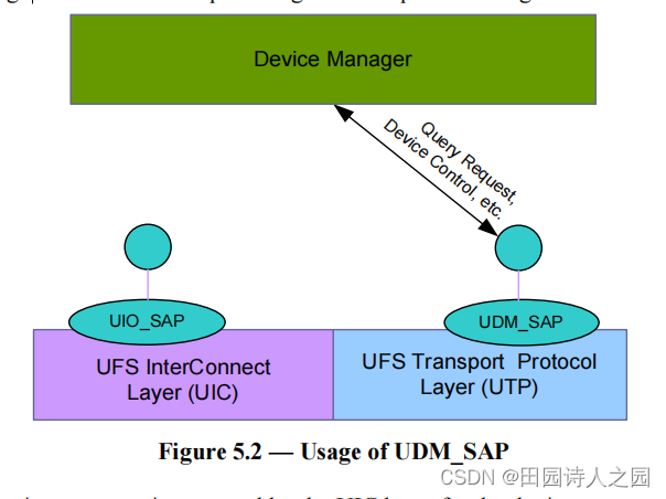
UDM_SAP is the service access point exposed by the UTP for the device manager to allow handling of device level operations and configurations. For example the handling of query request for descriptors would be done using this service access point. Figure 5.2 depicts the usage of the service access point.
UDM_SAP 是 UTP 为设备管理器公开的服务访问点,以允许处理设备级操作和配置。例如,描述符查询请求的处理将使用此服务访问点来完成。图 5.2 描述了服务访问点的用法。
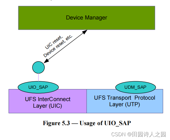
UIO_SAP is the service access point exposed by the UIC layer for the device manager to trigger the reset of the UIC layer and to transfer requests and responses related to UIC management functions. Figure 5.3 depicts the usage of the service access point.
UIO_SAP是UIC层对外暴露的服务接入点,用于设备管理器触发UIC层的复位,传递与UIC管理功能相关的请求和响应。图 5.3 描述了服务访问点的用法。
2.1.4 UFS Transport Protocol Layer
The UFS Transport Protocol (UTP) layer provides services for the higher layer . UPIU is “UFS Protocol Information Unit” which is exchanged between UTP layers of UFS host and UFS device. For example, if host side UTP receives the request from application layer or Device Manager, UTP generates a UPIU for that request and transports the generated UPIU to the peer UTP in UFS device side. The UTP layer provides the following three access points.
UFS 传输协议 (UTP) 层为更高层提供服务。 UPIU是UFS主机和UFS设备的UTP层之间交换的“UFS协议信息单元”。例如,如果主机端 UTP 收到来自应用层或设备管理器的请求,UTP 会为该请求生成一个 UPIU,并将生成的 UPIU 传输到 UFS 设备端的对等 UTP。 UTP 层提供以下三个接入点。
-
- UFS Device Manager Service Access Point (UDM_SAP) to perform the device level management like descriptor access.
- UFS 设备管理器服务访问点 (UDM_SAP) 执行设备级管理,如描述符访问。
-
- UTP Command Service Access Point (UTP_CMD_SAP) to transport commands
- UTP 命令服务访问点 (UTP_CMD_SAP) 以传输命令
-
- UTP Task Management Service Access Point (UTP_TM_SAP) to transport task-management function like “abort task” function.
- UTP 任务管理服务访问点 (UTP_TM_SAP) 用于传输任务管理功能,如“中止任务”功能。
2.1.5 UFS Interconnect Layer
The lowest layer is UFS Interconnect Layer (UIC) which handles connection between UFS host and UFS device. UIC consists of MIPI UniPro and MIPI M-PHY. The UIC provides two service access points to upper layer. The UIC Service Access Point (UIC_SAP) to transport UPIU between UFS host and UFS device. The UIC_SAP corresponds to T_SAP in UniPro. The UIC IO control Service Access Point (UIO_SAP) to manage UIC. The UIO_SAP corresponds to DME_SAP in UniPro.
最底层是 UFS 互连层 (UIC),它处理 UFS 主机和 UFS 设备之间的连接。 UIC由MIPI UniPro和MIPI M-PHY组成。 UIC 向上层提供两个服务接入点。 UIC 服务访问点 (UIC_SAP) 在 UFS 主机和 UFS 设备之间传输 UPIU。 UIC_SAP 对应UniPro 中的T_SAP。 UIC IO控制服务访问点(UIO_SAP)来管理UIC。 UIO_SAP 对应UniPro 中的DME_SAP。
2.2 UFS System Model
Figure 5.4 shows an example of UFS system. It shows how a UFS host is connected to a UFS device, the position of UFS host controller and its related UFS HCI interface.
图 5.4 显示了 UFS 系统的示例。它显示了 UFS 主机如何连接到 UFS 设备,UFS 主机控制器的位置及其相关的 UFS HCI 接口。
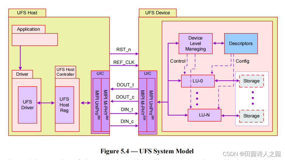
The UFS host consists of the application which wishes to communicate with the UFS device. It communicates with the device using the UFS driver. The UFS driver is meant for managing the UFS host controller through the UFS HCI (UFS Host Controller Interface). The UFS HCI is basically a set of registers exposed by the host controller.
UFS 主机由希望与 UFS 设备通信的应用程序组成。它使用 UFS 驱动程序与设备通信。 UFS 驱动程序用于通过 UFS HCI(UFS 主机控制器接口)管理 UFS 主机控制器。 UFS HCI 基本上是主机控制器公开的一组寄存器。
Figure 5.4 also indicates the UFS interface between the UFS host and the UFS device. The UFS Interconnect (UIC) Layer consists of MIPI UniPro and MIPI M-PHY. The physical layer M‐PHY is differential, dual simplex PHY that includes TX and RX pairs.
图 5.4 还指示了 UFS 主机和 UFS 设备之间的 UFS 接口。 UFS 互连 (UIC) 层由 MIPI UniPro 和 MIPI M-PHY 组成。物理层 M-PHY 是差分的双单工 PHY,包括 TX 和 RX 对。
Potential UFS devices can be memory card (full size and micro size), embedded bootable mass storage devices, IO devices, etc. A UFS device is comprised of multiple logical units, a device manager and descriptors. The device manager performs device level functions like power management while the logical unit performs functions like read, write etc. The descriptors are meant for storage of configuration related information.
潜在的 UFS 设备可以是存储卡(全尺寸和微型尺寸)、嵌入式可引导大容量存储设备、IO 设备等。一个 UFS 设备由多个逻辑单元、一个设备管理器和描述符组成。设备管理器执行设备级功能,如电源管理,而逻辑单元执行读、写等功能。描述符用于存储配置相关信息。
