一、PWM死区时间如何计算?
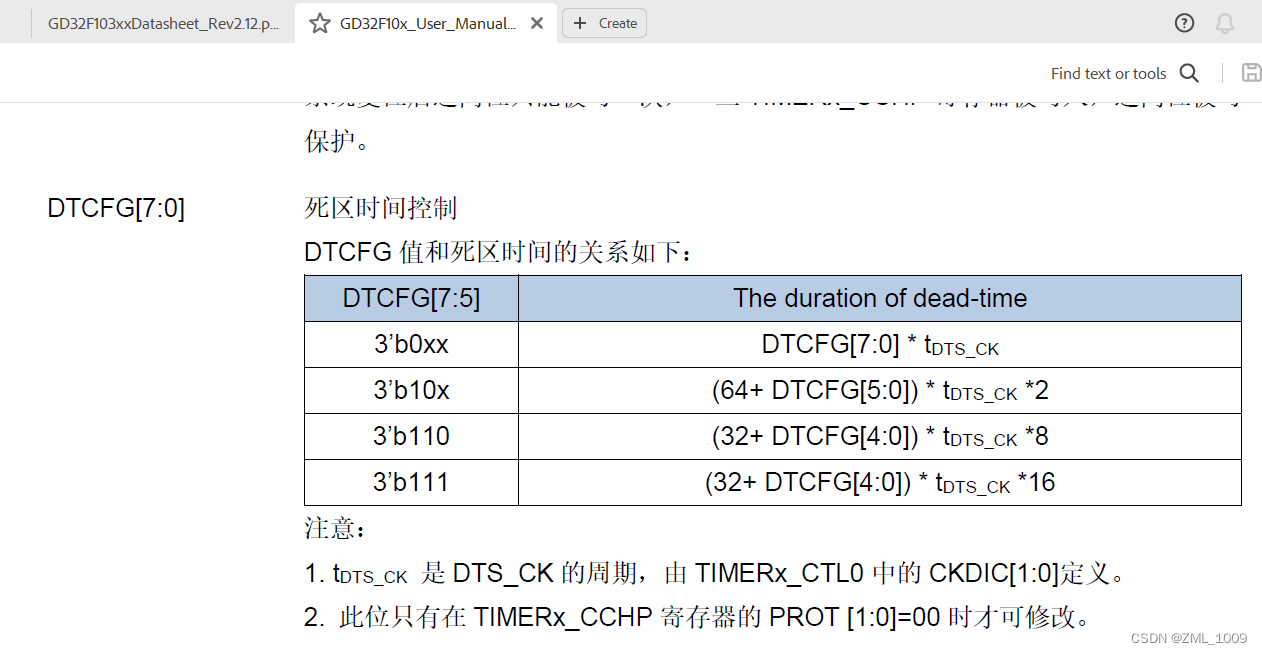
GD32F103的数据手册关于死区时间控制的公式如上图。
DTCFG的值为 设置死区结构体的寄存器值
tDTS_CK的值为 系统时钟的时钟周期。
如:GD32F103的系统时钟是108Mhz, 则tDTS_CK = 1/108Mhz = 9.26ns。( stm32的这个值跟定时器的时钟有关,但GD32跟系统时钟有关,要注意区别)
对于该死区时间计算对应有四种情况:
1:3’b0xx DTCFG[7:0] * tDTS_CK
DeadTime = DTCFG[7:0] * tDTS_CK = ( 0 ~ 127 ) * 9.26ns
即DeadTime = 0 ~ 1176.02ns
---------------------------------------------------------------------------------------------------------------------------------
举例:需要设置死区时间为320ns,则需要设置的死区寄存器值为 320/9.26 = 35 = 0x23
---------------------------------------------------------------------------------------------------------------------------------
2:3’b10x (64+ DTCFG[5:0]) * tDTS_CK *2
DeadTime = (64+ DTCFG[5:0]) * tDTS_CK *2 = (64 + DTCFG[5:0]) * 9.26ns *2
DeadTime = (64 + (0~63)) * 9.26ns *2 = ( 64 ~ 127 ) *9.26ns*2
DeadTime = 1185.92ns ~ 2353.31ns
---------------------------------------------------------------------------------------------------------------------------------
举例:需要设定死区时间为2000ns, 则需要设置的死区寄存器值为:
2000ns = (64+ x )* 9.26ns*2
x = 2000/( 9.26ns*2) - 64
x = 44 = 0010 1100;
补齐高两位DTCFG[7:6] = 10.
则x = 1010 1100 = 0xAC
---------------------------------------------------------------------------------------------------------------------------------
3:3’b110x (32+ DTCFG[4:0]) * tDTS_CK *8
DeadTime = (32+ DTCFG[4:0]) * tDTS_CK *8 = (32+ DTCFG[4:0]) * 9.26ns *8
DeadTime = (32+ (0~31)) * 9.26ns *8 = ( 32~ 63 ) *9.26ns*8
DeadTime = 2370.56ns ~ 4667.04ns
---------------------------------------------------------------------------------------------------------------------------------
举例:方法参考 情况2。 计算得出死区寄存器值,换算成二进制, 再在高位补齐110.得到完整8位二进制数,再转化成十六进制,带入程序的死区寄存器值
---------------------------------------------------------------------------------------------------------------------------------
4:3’b111x (32+ DTCFG[4:0]) * tDTS_CK *16
DeadTime = (32+ DTCFG[4:0]) * tDTS_CK *16 = (32+ DTCFG[4:0]) * 9.26ns *16
DeadTime = (32+ (0~31)) * 9.26ns *16 = ( 32~ 63 ) *9.26ns*16
DeadTime = 4741.12ns ~ 9334.08ns
---------------------------------------------------------------------------------------------------------------------------------
举例:方法参考 情况2。 计算得出死区寄存器值,换算成二进制, 再在高位补齐111.得到完整8位二进制数,再转化成十六进制,带入程序的死区寄存器值
---------------------------------------------------------------------------------------------------------------------------------
二、TIMR0 PWM程序配置
		/* timer para init */
		timer_parameter_struct timer_initpara;
		/* timer channel output para init */
		timer_oc_parameter_struct timer_ocinitpara;
		/* timer break para init */
		timer_break_parameter_struct timer_breakpara;

		rcu_periph_clock_enable(RCU_TIMER0);
		timer_deinit(TIMER0);

		/* initialize TIMER init parameter struct */
		timer_struct_para_init(&timer_initpara);
		/* TIMER0 configuration */
		timer_initpara.prescaler         = 3-1;   						/* 108MHz/(2+1) = 36MHz for Timer0 			*/
		timer_initpara.alignedmode       = TIMER_COUNTER_EDGE;   		/* aligned mode using EDGE 					*/
		timer_initpara.counterdirection  = TIMER_COUNTER_UP;     		/* Counter direction using UP 				*/
		timer_initpara.period            = 2250-1;                 		/* Period= 1/36MHz * (2249+1) =62.5us 16KHz */
		timer_initpara.clockdivision     = TIMER_CKDIV_DIV1;			/* time divide, 1-> not divide 				*/
		timer_initpara.repetitioncounter = 0;                    		/* repetition counter 						*/
		timer_init(TIMER0, &timer_initpara);

		/* initialize TIMER channel output parameter struct */
		timer_channel_output_struct_para_init(&timer_ocinitpara);
		/* CH0/CH0N, CH1/CH1N and CH2/CH2N configuration in timing mode */
		timer_ocinitpara.outputstate     = TIMER_CCX_DISABLE;        	/* Enable output Chanalx state 				*/
		timer_ocinitpara.outputnstate    = TIMER_CCXN_DISABLE;       	/* Enable output ChanalxN state 			*/
		timer_ocinitpara.ocpolarity      = TIMER_OC_POLARITY_HIGH;   	/* Chanalx Polarity 						*/
		timer_ocinitpara.ocnpolarity     = TIMER_OCN_POLARITY_HIGH;  	/* ChanalxN Polarity 						*/
		timer_ocinitpara.ocidlestate     = TIMER_OC_IDLE_STATE_LOW;  	/* Chanalx idle state 						*/
		timer_ocinitpara.ocnidlestate    = TIMER_OCN_IDLE_STATE_LOW;  	/* ChanalxN idle state 						*/

		timer_channel_output_config(TIMER0, TIMER_CH_0, &timer_ocinitpara);
		timer_channel_output_config(TIMER0, TIMER_CH_1, &timer_ocinitpara);

		/* configure TIMER channel 0, duty cycle 0% */
		timer_channel_output_pulse_value_config(TIMER0, TIMER_CH_0, 0U);
		timer_channel_output_mode_config(TIMER0, TIMER_CH_0, TIMER_OC_MODE_PWM0);
		timer_channel_output_shadow_config(TIMER0, TIMER_CH_0, TIMER_OC_SHADOW_ENABLE);

		/* configure TIMER channel 1, duty cycle 0% */
		timer_channel_output_pulse_value_config(TIMER0, TIMER_CH_1, 0U);
		timer_channel_output_mode_config(TIMER0, TIMER_CH_1, TIMER_OC_MODE_PWM0);
		timer_channel_output_shadow_config(TIMER0, TIMER_CH_1, TIMER_OC_SHADOW_ENABLE);

		/* initialize TIMER break parameter struct */
		timer_break_struct_para_init(&timer_breakpara);
		/* automatic output enable, break, dead time and lock configuration*/
		timer_breakpara.runoffstate      = TIMER_ROS_STATE_ENABLE;
		timer_breakpara.ideloffstate     = TIMER_IOS_STATE_ENABLE;
		timer_breakpara.deadtime         = PWM_BREAK_DEAD_TIME;				/* Dead time */
		timer_breakpara.breakpolarity    = TIMER_BREAK_POLARITY_LOW;
		timer_breakpara.outputautostate  = TIMER_OUTAUTO_ENABLE;
		timer_breakpara.protectmode      = TIMER_CCHP_PROT_OFF;
		timer_breakpara.breakstate       = TIMER_BREAK_DISABLE;
		timer_break_config(TIMER0, &timer_breakpara);

		/* TIMER0 primary output function enable */
		timer_primary_output_config(TIMER0, ENABLE);
		/* auto-reload preload enable */
		timer_auto_reload_shadow_enable(TIMER0);

		timer_enable(TIMER0);
其中PWM_BREAK_DEAD_TIME 就是要设置的死区寄存器值,可以宏定义
#define PWM_BREAK_DEAD_TIME 0XACU
总结
以上就是今天要讲的内容,本文介绍了GD32F103 PWM死区时间的计算

