管理vlan
远程连接一个二层交换机,由于二层交换机不能配IP地址,所以我们使用SVI交换虚拟接口配置一个IP地址来远程连接二层交换机。svi接口可以配置ip地址,出厂存在mac地址,用于远程登陆管理该设备,该接口默认在vlan1,所以vlan1为管理vlan。
实例:

配置sw0的svi接口在vlan1中的ip地址
Switch(config)#interface vlan 1
Switch(config-if)#ip address 192.168.1.1 255.255.255.0
Switch(config-if)#no shutdown
开启sw0的远程登录认证
Switch(config)#username huangfei privilege 15 password cisco123
Switch(config)#line vty 0 4
Switch(config-line)#login local
Switch(config-line)#
用pc0远程登录管理该交换机

二层交换机仅存在一个svi,默认在vlan1中,如果该svi转移到了其它vlan接口,则之前的vlan接口自动被关闭。三层交换机支持多个svi
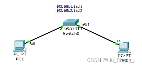
创建一个vlan2将svi移动到vlan2接口让vlan2成为管理vlan
Switch(config)#vlan 2
Switch(config-vlan)#exit
Switch(config)#interface vlan 2
Switch(config-if)#
%LINK-5-CHANGED: Interface Vlan2, changed state to up

Switch(config-if)#ip address 192.168.2.1 255.255.255.0
Switch(config-if)#no shutdown
查看ip地址表

我们知道svi接口只能存在于一个vlan接口里面,所以vlan2是down状态
关闭vlan1接口,并且让交换机连接pc1的接口划分到vlan2
Switch(config)#interface vlan1
Switch(config-if)#shutdown
Switch(config-if)#exit
Switch(config)#interface fastEthernet 0/2
Switch(config-if)#switchport mode access
Switch(config-if)#switchport access vlan 2
可以发现vlan2接口成功双up

用pc1远程登录管理sw0

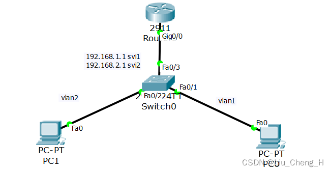
路由器配置单臂路由
Router(config)#interface gigabitEthernet 0/0
Router(config-if)#no shutdown
Router(config-if)#exit
Router(config)#interface gigabitEthernet 0/0.1
Router(config-subif)#
Router(config-subif)#encapsulation dot1Q 1
Router(config-subif)#ip address 192.168.1.254 255.255.255.0
Router(config-subif)#exit
Router(config)#interface gigabitEthernet 0/0.2
Router(config-subif)#
Router(config-subif)#encapsulation dot1Q 2
Router(config-subif)#ip address 192.168.2.254 255.255.255.0
Router(config-subif)#exit
Router(config)#
PC0和PC1能够通讯
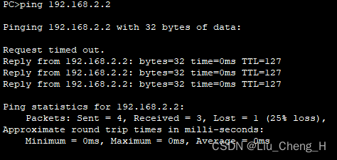
使用pc0去访问vlan2的svi,需要在交换机上配置网关
Switch(config)#ip default-gateway 192.168.2.254这样pc0也可以去远程登录交换机。
在我们的生活中,如果不希望别的广播域的人也能远程登录交换机,那么就不给交换机配置网关,这样只能与交换机管理vlan同一广播域能够配置交换机
华为的三层交换机可以有多个svi
[Huawei]interface Vlanif 2
[Huawei-Vlanif2]ip address 192.168.2.1 24

三层交换机
标准的三层交换机不具有nat功能,无法成为连接互联网的核心层设备;
默认情况下,cisco和华为的三层交换机所有物理接口为二层接口;
可以将三层交换机的接口修改具有三层功能的接口。
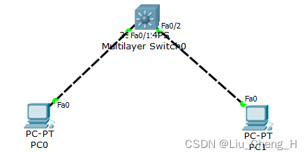
将三层交换机的两个接口关闭二层交换接口修改为三层功能的接口配置ip
sw0(config)#int fastEthernet 0/1
sw0(config-if)#no switchport
sw0(config-if)#ip address 192.168.1.254 255.255.255.0
sw0(config)#int fastEthernet 0/2
sw0(config-if)#no switchport
sw0(config-if)#ip address 192.168.2.254 255.255.255.0
注:华为的三层交换机默认存在3层路由功能,但cisco需要手工开启
sw0(config)#ip routing 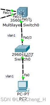
在sw0上配置svi接口管理vlan为vlan1
Switch(config)#interface vlan 1
Switch(config-if)#ip address 192.168.3.2 255.255.255.0
Switch(config-if)#no shutdown 
在三层交换机MSW0上配置svi接口
sw0#configure terminal
sw0(config)#interface vlan 1
sw0(config-if)#ip address 192.168.3.254 255.255.255.0
sw0(config-if)#no shutdown 
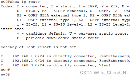
当我们查看MSW0的路由表时可以发现svi接口这条路由也被路由表当作了直连路由
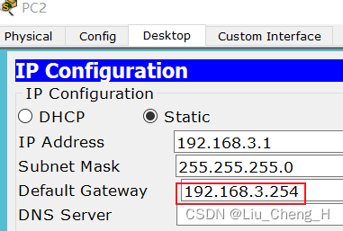
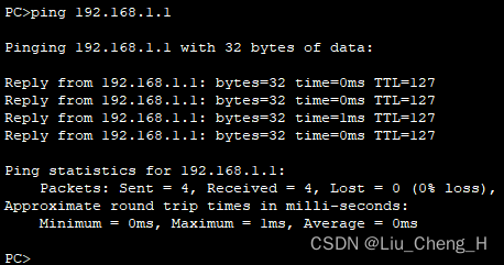
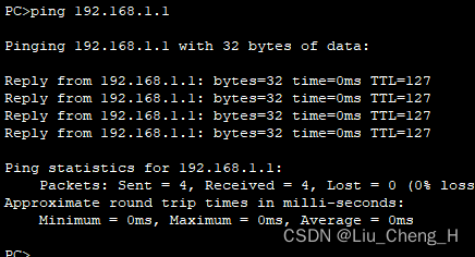
用PC2去pingPC0和PC1可以ping通,说明svi接口ip可以当作路由器网关。
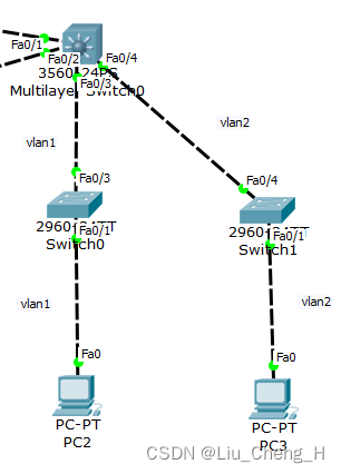
比单臂路由强的地方在于带宽增加,两条网线。
创建vlan2,在MSW0上配置svi接口,管理vlan为vlan2,将接口Fa0/4接口类型改为access并允许vlan2通过,将该svi接口作为vlan2的网关。
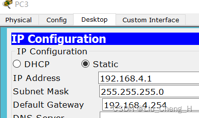
sw0(config)#vlan 2
sw0(config-vlan)#exit
sw0(config)#interface vlan 2
sw0(config-if)#ip address 192.168.4.254 255.255.255.0
sw0(config-if)#
sw0(config-if)#exit
sw0(config)#interface fastEthernet 0/4
sw0(config-if)#switchport mode access
sw0(config-if)#switchport access vlan 2
sw0(config-if)#
在sw2上创建vlan2,所有接口改为access允许vlan2通过
sw1(config-if-range)#vlan 2
sw1(config-vlan)#exit
sw1(config)#int range fastEthernet 0/1-24
sw1(config-if-range)#switchport mode access
sw1(config-if-range)#switchport access vlan 2
sw1(config-if-range)#spanning-tree portfast
VLAN2访问VLAN1,PC3pingPC2
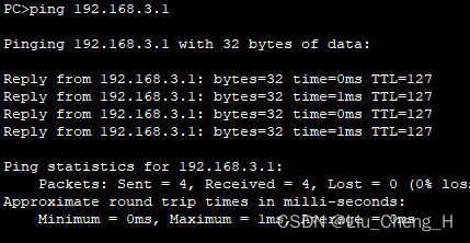
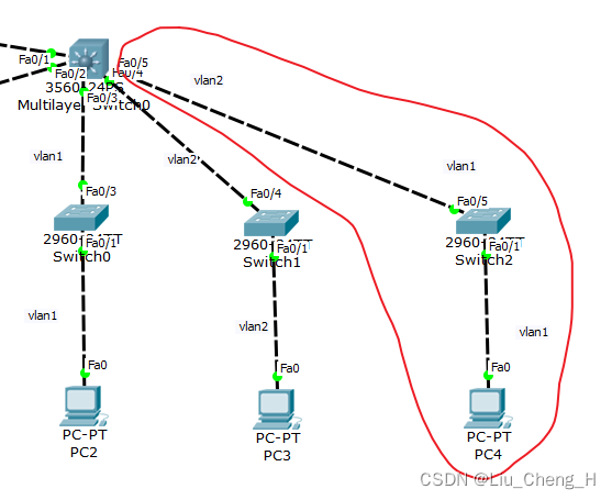
比单臂路由强在一个vlan2可以用两个网线
将fa0/5接口划入vlan2
sw0(config)#interface fastEthernet 0/5
sw0(config-if)#switchport mode access
sw0(config-if)#switchport access vlan 2
sw0(config-if)#
将管理VLAN2的svi接口作为PC4的网关


MSW0和sw3之间设为Trunk干道
sw0(config)#interface fastEthernet 0/6
sw0(config-if)#switchport trunk encapsulation dot1q
sw0(config-if)#switchport mode trunk
sw0(config-if)#spanning-tree portfast
交换机sw3中 fa0/1划入vlan1,fa0/2划入vlan2
Switch(config-if)#vlan 2
Switch(config-vlan)#exit
Switch(config)#interface fa0/2
Switch(config-if)#switchport mode access
Switch(config-if)#switchport access vlan 2
Switch(config-if)#spanning-tree portfast
PC6去pingPC5和PC1

设备冗余 --- 三层交换机冗余

若使用基于vlan或基于分组的STP协议来工作三层架构中,将导致vlan间或组间通讯时对汇聚层间链路带宽要求较高;
所以在汇聚层的设备之间我们使用两根网线来进行信息通讯但是这样会造成环路;
通过以太网通道 channel (cisco ) 或者以太网中继Eth-Trunk(华为) 技术来解决;
通道技术将多个接口逻辑的整合为一个接口,实现带宽叠加的作用;
当其中一条链路断了,另外一条也可以继续用,实现备份的作用。
sw0(config)#interface range fastEthernet 0/7-8
sw0(config-if-range)#channel-group 1 mode on
sw0(config-if-range)#
Creating a port-channel interface Port-channel 1
MSW1(config)#interface range fa0/1-2
MSW1(config-if-range)#channel-group 1 mode on
MSW1(config-if-range)#
Creating a port-channel interface Port-channel 1
将两个逻辑接口逻辑为一个channel 1接口

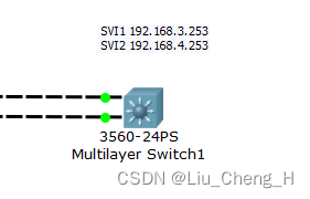
MSW1配置两个SVI

只能ping通对方的SVI1,ping不通对方的SVI2是为什么?SVI2属于vlan2,因为交换机之间的接口默认都是vlan1,需要设为trunk才能ping通SV2
设置trunk干道
MSW0(config)#interface range fastEthernet 0/7-8
MSW0(config-if-range)#switchport trunk encapsulation dot1q
MSW0(config-if-range)#switchport mode trunk
MSW1(config)#interface range fastEthernet 0/1-2
MSW1(config-if-range)#switchport trunk encapsulation dot1q
MSW1(config-if-range)#switchport mode trunk 成功ping通


sw4(config)#interface fastEthernet 0/3
sw4(config-if)#switchport mode trunk
sw4(config-if)#
sw4(config-if)#vlan 2
sw4(config-vlan)#exit
sw4(config)#interface fastEthernet 0/2
sw4(config-if)#switchport mode access
sw4(config-if)#switchport access vlan  2
vlan1的PC之间互相不需要网关都能通讯, vlan2的PC之间互相不需要网关也能通讯,因为他们同一个vlan内属于同一个广播域,只需要交换机进行转发就可以了。
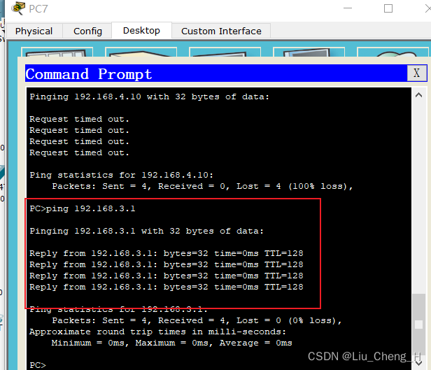


使用PC7pingPC8
在交换机MSW1手工开启路由功能
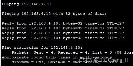
MSW1(config)#ip routing以SVI1和SV2作为PC7和PC8的网关
根网桥、网关 应该放在同一台汇聚层设备上实现三合一
PC8为什么不能访问PC1,因为PC8网关为右边三层交换机的SVI2,路由表中没有到达PC1的路由,添加静态路由
MSW1(config)#ip route 192.168.1.0 255.255.255.0 192.168.3.254
MSW1(config)#ip route 192.168.2.0 255.255.255.0 192.168.4.254
二层通道与三层通道
二层通道用于汇聚层(VLAN/STP/SVI都位于汇聚层)中进行带宽叠加 负载分担负载均衡都可实现
三层通道用于核心层中进行链路备份的时候能够节约一个网段,在路由器之间多根网线配置一个ip地址就可以了 负载均衡
网关冗余
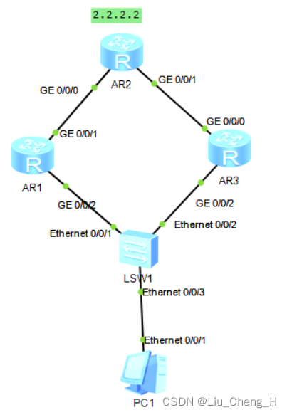
在这个拓扑图中,R1和R3都可以作为PC1的网关
设置网关冗余
[R1]int GigabitEthernet 0/0/2
[R1-GigabitEthernet0/0/2]vrrp vrid 1 virtual-ip 13.1.1.250
[R3]int g0/0/2
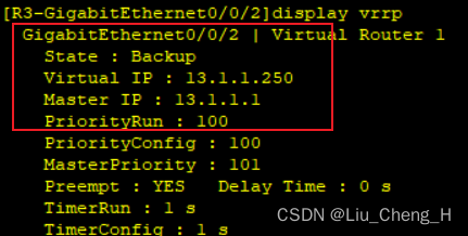
[R3-GigabitEthernet0/0/2]vrrp vrid 1 virtual-ip 13.1.1.250将PC1的优先级设为101作为master网关
[R1]int GigabitEthernet 0/0/2
[R1-GigabitEthernet0/0/2]vrrp vrid 1 priority 101

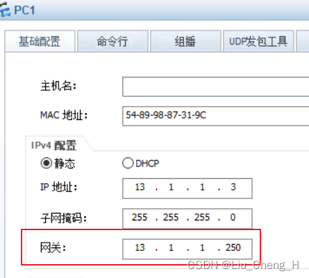
PC3的网关默认为100作为backup网关,R1和R3一秒一个hello包维持关系
用PC3去ping2.2.2.2,此时R3为PC1的备份网关,ICMP包通过R1去访问2.2.2.2;
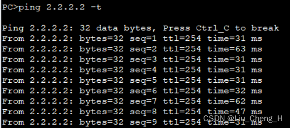
当R1断开后,此时网络断开,并且R1不再发送hello包;

R3收不到hello包后充当master网关,网络重新连接通过R3访问2.2.2.2;


R1恢复后和R3抢夺master网关地位,此时网络又断开;

R3抢夺失败,变为backup网关,网络重新连接通过R1访问2.2.2.2
