实验一 选择器
2选1多路选择器
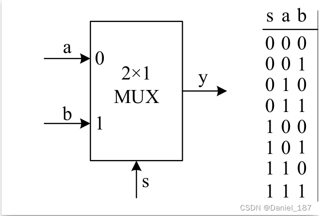
逻辑表达式:
y
=
(
∼
s
&
a
)
∣
(
s
&
b
)
y=(\sim s\&a)|(s\&b)
y=(∼s&a)∣(s&b)
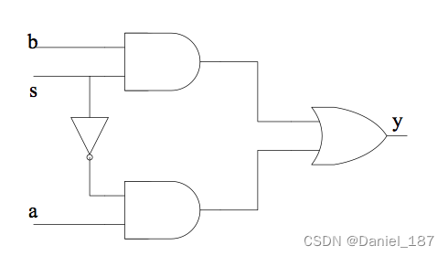
逻辑电路:
数据流建模
数据流建模主要是通过连续赋值语句 assign 来描述电路的功能
module m_mux21(a,b,s,y);
  input   a,b,s;        // 声明3个wire型输入变量a,b,和s,其宽度为1位。
  output  y;           // 声明1个wire型输出变量y,其宽度为1位。

  assign  y = (~s&a)|(s&b);  // 实现电路的逻辑功能。

endmodule
仿真代码:
#include "verilated.h"
#include "verilated_vcd_c.h"
#include "obj_dir/Vmux21.h"
VerilatedContext* contextp = NULL;
VerilatedVcdC* tfp = NULL;
static Vmux21* top;
void step_and_dump_wave(){
top->eval();
contextp->timeInc(1);
tfp->dump(contextp->time());
}
void sim_init(){
contextp = new VerilatedContext;
tfp = new VerilatedVcdC;
top = new Vmux21;
contextp->traceEverOn(true);
top->trace(tfp, 0);
tfp->open("dump.vcd");
}
void sim_exit(){
step_and_dump_wave();
tfp->close();
}
int main() {
sim_init();
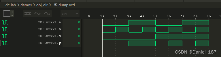
top->s=0; top->a=0; top->b=0; step_and_dump_wave(); // 将s,a和b均初始化为“0”
top->b=1; step_and_dump_wave(); // 将b改为“1”,s和a的值不变,继续保持“0”,
top->a=1; top->b=0; step_and_dump_wave(); // 将a,b分别改为“1”和“0”,s的值不变,
top->b=1; step_and_dump_wave(); // 将b改为“1”,s和a的值不变,维持10个时间单位
top->s=1; top->a=0; top->b=0; step_and_dump_wave(); // 将s,a,b分别变为“1,0,0”,维持10个时间单位
top->b=1; step_and_dump_wave();
top->a=1; top->b=0; step_and_dump_wave();
top->b=1; step_and_dump_wave();
sim_exit();
}
编译:
verilator -Wall --cc --exe --build main.cpp mux21.v --trace
波形:
结构化建模
结构化建模主要通过逐层实例化子模块的方式来描述电路的功能
module my_and(a,b,c);
  input  a,b;
  output c;

  assign c = a & b;
endmodule

module my_or(a,b,c);
  input  a,b;
  output c;

  assign c = a | b;
endmodule

module my_not(a,b);
  input  a;
  output b;

  assign b = ~a;
endmodule

module mux21b(a,b,s,y);
  input  a,b,s;
  output y;

  wire l, r, s_n; // 内部网线声明
  my_not i1(.a(s), .b(s_n));        // 实例化非门,实现~s
  my_and i2(.a(s_n), .b(a), .c(l)); // 实例化与门,实现(~s&a)
  my_and i3(.a(s),   .b(b), .c(r)); // 实例化与门,实现(s&b)
  my_or  i4(.a(l),   .b(r), .c(y)); // 实例化或门,实现(~s&a)|(s&b)
endmodule
行为建模
行为建模是通过类似面向过程的编程语言来描述电路的行为。例如,在Verilog中也可以用if语句来实现2选1多路选择器的行为
module mux21c(a,b,s,y);
  input   a,b,s;
  output reg  y;   // y在always块中被赋值,一定要声明为reg型的变量

  always @ (*)
    if(s==0)
      y = a;
    else
      y = b;
endmodule

//或者使用条件表达式
module mux21d(a,b,s,y);
  input   a,b,s;
  output  y;   // y不用声明为reg型的了。
  assign  y = s ? b : a;
endmodule
真正的描述电路 = 实例化 + 连线,所以请尽量不要使用“行为级建模”
4选1多路选择器
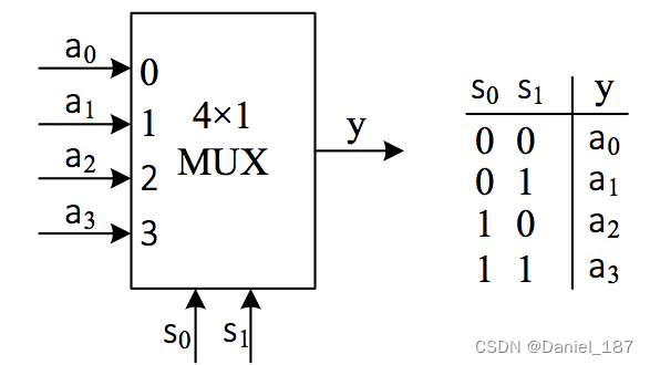
module mux41(a,s,y);
  input  [3:0] a;  // 声明一个wire型输入变量a,其变量宽度是4位的。
  input  [1:0] s;  // 声明一个wire型输入变量s,其变量宽度是2位的。
  output reg y;   // 声明一个1位reg型的输出变量y。

  always @ (s or a)
    case (s)
      0: y = a[0];
      1: y = a[1];
      2: y = a[2];
      3: y = a[3];
      default: y = 1'b0;
    endcase

endmodule
测试代码:
#include "verilated.h"
#include "verilated_vcd_c.h"
#include "obj_dir/Vmux41.h"
VerilatedContext* contextp = NULL;
VerilatedVcdC* tfp = NULL;
static Vmux41* top;
void step_and_dump_wave(){
top->eval();
contextp->timeInc(1);
tfp->dump(contextp->time());
}
void sim_init(){
contextp = new VerilatedContext;
tfp = new VerilatedVcdC;
top = new Vmux41;
contextp->traceEverOn(true);
top->trace(tfp, 0);
tfp->open("dump.vcd");
}
void sim_exit(){
step_and_dump_wave();
tfp->close();
}
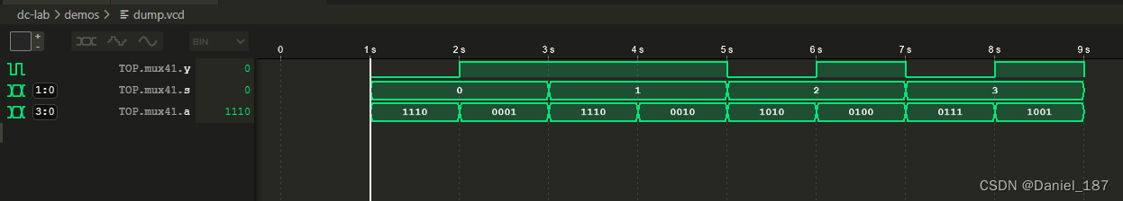
int main() {
sim_init();
top->s=0b00; top->a=0b1110; step_and_dump_wave();
top->a=0b0001; step_and_dump_wave();
top->s=0b01; top->a=0b1110; step_and_dump_wave();
top->a=0b0010; step_and_dump_wave();
top->s=0b10; top->a=0b1010; step_and_dump_wave();
top->a=0b0100; step_and_dump_wave();
top->s=0b11; top->a=0b0111; step_and_dump_wave();
top->a=0b1001; step_and_dump_wave();
sim_exit();
}
编译:
verilator -Wall --cc --exe --build main.cpp mux41.v --trace
波形:
一个通用的选择器模板
module MuxKeyInternal #(NR_KEY = 2, KEY_LEN = 1, DATA_LEN = 1, HAS_DEFAULT = 0) (
  output reg [DATA_LEN-1:0] out,
  input [KEY_LEN-1:0] key,
  input [DATA_LEN-1:0] default_out,
  input [NR_KEY*(KEY_LEN + DATA_LEN)-1:0] lut
);

  localparam PAIR_LEN = KEY_LEN + DATA_LEN;
  wire [PAIR_LEN-1:0] pair_list [NR_KEY-1:0];
  wire [KEY_LEN-1:0] key_list [NR_KEY-1:0];
  wire [DATA_LEN-1:0] data_list [NR_KEY-1:0];

  generate
    for (genvar n = 0; n < NR_KEY; n = n + 1) begin
      assign pair_list[n] = lut[PAIR_LEN*(n+1)-1 : PAIR_LEN*n];
      assign data_list[n] = pair_list[n][DATA_LEN-1:0];
      assign key_list[n]  = pair_list[n][PAIR_LEN-1:DATA_LEN];
    end
  endgenerate

  reg [DATA_LEN-1 : 0] lut_out;
  reg hit;
  integer i;
  always @(*) begin
    lut_out = 0;
    hit = 0;
    for (i = 0; i < NR_KEY; i = i + 1) begin
      lut_out = lut_out | ({DATA_LEN{key == key_list[i]}} & data_list[i]);
      hit = hit | (key == key_list[i]);
    end
    if (!HAS_DEFAULT) out = lut_out;
    else out = (hit ? lut_out : default_out);
  end

endmodule

module MuxKey #(NR_KEY = 2, KEY_LEN = 1, DATA_LEN = 1) (
  output [DATA_LEN-1:0] out,
  input [KEY_LEN-1:0] key,
  input [NR_KEY*(KEY_LEN + DATA_LEN)-1:0] lut
);
  MuxKeyInternal #(NR_KEY, KEY_LEN, DATA_LEN, 0) i0 (out, key, {DATA_LEN{1'b0}}, lut);
endmodule

module MuxKeyWithDefault #(NR_KEY = 2, KEY_LEN = 1, DATA_LEN = 1) (
  output [DATA_LEN-1:0] out,
  input [KEY_LEN-1:0] key,
  input [DATA_LEN-1:0] default_out,
  input [NR_KEY*(KEY_LEN + DATA_LEN)-1:0] lut
);
  MuxKeyInternal #(NR_KEY, KEY_LEN, DATA_LEN, 1) i0 (out, key, default_out, lut);
endmodule
使用选择器模板实现的选择器:
module mux21e(a,b,s,y);
  input   a,b,s;
  output  y;
  MuxKey #(2, 1, 1) i0 (y, s, {
    1'b0, a,
    1'b1, b
  });
endmodule

module mux41b(a,s,y);
  input  [3:0] a;
  input  [1:0] s;
  output y;
  MuxKeyWithDefault #(4, 2, 1) i0 (y, s, 1'b0, {
    2'b00, a[0],
    2'b01, a[1],
    2'b10, a[2],
    2'b11, a[3]
  });
endmodule
实验验收内容
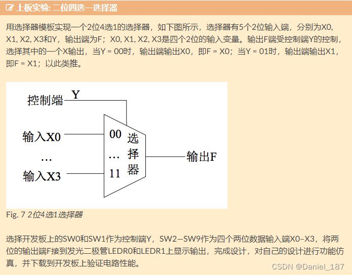
module mux41(x0, x1, x2, x3, y, f);
  input  [1:0] x0;
  input  [1:0] x1;
  input  [1:0] x2;
  input  [1:0] x3;
  input  [1:0] y;  // 声明一个wire型输入变量s,其变量宽度是2位的。
  output reg [1:0] f;   // 声明一个2位reg型的输出变量y。

  MuxKeyWithDefault #(4, 2, 2) i0 (f, y, 2'b00, {
    2'b00, x0,
    2'b01, x1,
    2'b10, x2,
    2'b11, x3
  });

endmodule
先输出波形尝试一下:
#include "verilated.h"
#include "verilated_vcd_c.h"
#include "obj_dir/Vmux41.h"
VerilatedContext* contextp = NULL;
VerilatedVcdC* tfp = NULL;
static Vmux41* top;
void step_and_dump_wave(){
top->eval();
contextp->timeInc(1);
tfp->dump(contextp->time());
}
void sim_init(){
contextp = new VerilatedContext;
tfp = new VerilatedVcdC;
top = new Vmux41;
contextp->traceEverOn(true);
top->trace(tfp, 0);
tfp->open("dump.vcd");
}
void sim_exit(){
step_and_dump_wave();
tfp->close();
}
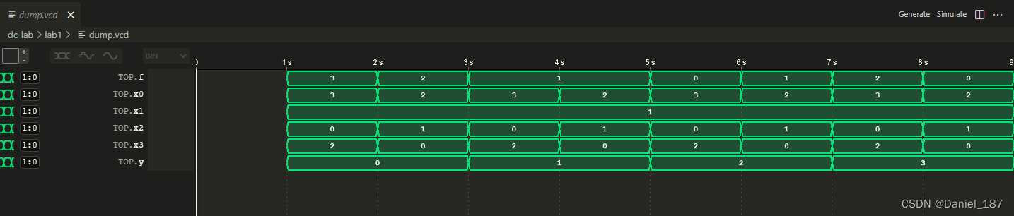
int main() {
sim_init();
top->y=0b00; top->x0=0b11; top->x1=0b01; top->x2=0b00; top->x3=0b10; step_and_dump_wave();
top->x0=0b10; top->x1=0b01; top->x2=0b01; top->x3=0b00; step_and_dump_wave();
top->y=0b01; top->x0=0b11; top->x1=0b01; top->x2=0b00; top->x3=0b10; step_and_dump_wave();
top->x0=0b10; top->x1=0b01; top->x2=0b01; top->x3=0b00; step_and_dump_wave();
top->y=0b10; top->x0=0b11; top->x1=0b01; top->x2=0b00; top->x3=0b10; step_and_dump_wave();
top->x0=0b10; top->x1=0b01; top->x2=0b01; top->x3=0b00; step_and_dump_wave();
top->y=0b11; top->x0=0b11; top->x1=0b01; top->x2=0b00; top->x3=0b10; step_and_dump_wave();
top->x0=0b10; top->x1=0b01; top->x2=0b01; top->x3=0b00; step_and_dump_wave();
sim_exit();
}
编译:
verilator -Wall --cc --exe --build main.cpp *.v --trace --top-module mux41
波形:
接入NVBoard:
目录结构:
$ tree -I build/
.
├── constr
│   └── top.nxdc
├── csrc
│   └── main.cpp
├── Makefile
└── vsrc
    ├── mux41.v
    ├── MuxKeyInternal.v
    ├── MuxKey.v
    └── MuxKeyWithDefault.v

3 directories, 7 files
测试文件:
#include "Vmux41.h"
#include "verilated.h"
#include <nvboard.h>

static TOP_NAME dut;

void nvboard_bind_all_pins(Vmux41* top);

static void single_cycle() {
	dut.eval();
}

int main(int argc, char** argv) {
  nvboard_bind_all_pins(&dut);
  nvboard_init();

  while (1) {
	  nvboard_update();
	  single_cycle();
  }
   return 0;
}
引脚约束:
top=mux41

f (LD1, LD0)
y (SW1, SW0)

x0 (SW3, SW2)
x1 (SW5, SW4)
x2 (SW7, SW6)
x3 (SW9, SW8)
makefile将之前的第一行改为TOPNAME = mux41即可
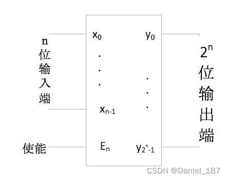
实验二 译码器和编码器
译码器
2-4译码器
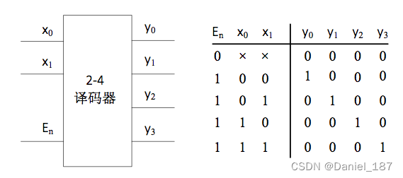
module decode24(x,en,y);
  input  [1:0] x;
  input  en;
  output reg [3:0]y;

  always @(x or en)
    if (en)
    begin
      case (x)
            2'd0 : y = 4'b0001;
            2'd1 : y = 4'b0010;
            2'd2 : y = 4'b0100;
            2'd3 : y = 4'b1000;
      endcase
    end
    else  y = 4'b0000;

endmodule
测试代码:
int main() {
  sim_init();

  top->en = 0b0;  top->x = 0b00;  step_and_dump_wave();
                  top->x = 0b01;  step_and_dump_wave();
                  top->x = 0b10;  step_and_dump_wave();
                  top->x = 0b11;  step_and_dump_wave();
  top->en = 0b1;  top->x = 0b00;  step_and_dump_wave();
                  top->x = 0b01;  step_and_dump_wave();
                  top->x = 0b10;  step_and_dump_wave();
                  top->x = 0b11;  step_and_dump_wave();
  sim_exit();
}
使用for循环实现3-8译码器:
module decode38(x,en,y);
  input  [2:0] x;
  input  en;
  output reg [7:0]y;
  integer i;

  always @(x or en)
    if (en) begin
      for( i = 0; i <= 7; i = i+1)
          if(x == i)
                y[i] = 1;
          else
                y[i] = 0;
    end
    else
      y = 8'b00000000;

endmodule
编码器
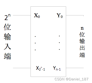
4-2编码器
module encode42(x,en,y);
  input  [3:0] x;
  input  en;
  output reg [1:0]y;

  always @(x or en) begin
    if (en) begin
      case (x)
          4'b0001 : y = 2'b00;
          4'b0010 : y = 2'b01;
          4'b0100 : y = 2'b10;
          4'b1000 : y = 2'b11;
          default: y = 2'b00;
      endcase
    end
    else  y = 2'b00;
  end
endmodule
测试代码:
int main() {
  sim_init();

  top->en=0b0; top->x =0b0000; step_and_dump_wave();
               top->x =0b0001; step_and_dump_wave();
               top->x =0b0010; step_and_dump_wave();
               top->x =0b0100; step_and_dump_wave();
               top->x =0b1000; step_and_dump_wave();
  top->en=0b1; top->x =0b0000; step_and_dump_wave();
               top->x =0b0001; step_and_dump_wave();
               top->x =0b0010; step_and_dump_wave();
               top->x =0b0100; step_and_dump_wave();
               top->x =0b1000; step_and_dump_wave();
  sim_exit();
}
优先编码器
优先编码器允许同时在几个输入端有输入信号,即输入不止一个 1 ,编码器按输入信号排定的优先顺序,只对同时输入的几个信号中优先权最高的一个进行编码
我们可以利用for循环语句可以很方便地实现优先编码器,一个4-2优先编码器的示例如下所示
module encode42(x,en,y);
  input  [3:0] x;
  input  en;
  output reg [1:0]y;
  integer i;
  always @(x or en) begin
    if (en) begin
      y = 0;
      for( i = 0; i <= 3; i = i+1)
          if(x[i] == 1)  y = i[1:0];
    end
    else  y = 0;
  end
endmodule
七段数码管

模块实例化
七段数码管就是一个典型的可复用模块
module bcd7seg(
  input  [3:0] b,
  output reg [6:0] h
);
// detailed implementation ...

endmodule
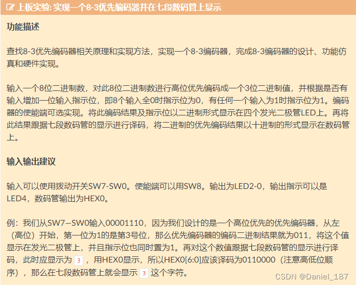
实验验收内容
目录结构:
$ tree -I build/
.
├── constr
│   └── top.nxdc
├── csrc
│   └── main.cpp
├── Makefile
└── vsrc
    ├── bcd7seg.v
    ├── encode83.v
    └── top.v

3 directories, 6 files
/**bcd7seg.v**/
module bcd7seg(
  input  [3:0] b,
  output reg [6:0] h
);
// detailed implementation ...

always@(b) begin
	case(b)
	4'd0: h<=7'b000_0001;
	4'd1: h<=7'b100_1111;
	4'd2: h<=7'b001_0010;
	4'd3: h<=7'b000_0110;
	4'd4: h<=7'b100_1100;
	4'd5: h<=7'b010_0100;
	4'd6: h<=7'b010_0000;
	4'd7: h<=7'b000_1111;
	4'd8: h<=7'b000_0000;
	4'd9: h<=7'b000_0100;
	default: h<=7'b000_0001;
	endcase
end

endmodule


/**encod38.v**/
module encode38(x,en,y, indicate);
  input  [7:0] x;
  input  en;
  output reg [2:0]y;
  output reg indicate;

  integer i;
  always @(x or en) begin
    if (en) begin
      y = 0;
      if (x != 0) indicate <= 1'b1;
      else indicate <= 1'b0;
      for( i = 0; i <= 7; i = i+1)
          if(x[i] == 1)  y = i[2:0];
    end
    else  y = 0;
  end
endmodule


/**top.v**/
module top(
    input [7:0]sw,
    input en,
    output reg [2:0] led_out,
    output reg indicate,
    output reg [6:0] seg_out
);

wire [2:0]w;

assign led_out = w;

encode38 encdr(
    .x(sw),
    .en(en),
    .y(w),
    .indicate(indicate)
);

bcd7seg seg0(
    .b({1'b0,w}),
    .h(seg_out)
);
endmodule
测试文件:
#include "Vtop.h"
#include "verilated.h"
#include <nvboard.h>

static TOP_NAME dut;

void nvboard_bind_all_pins(Vtop* top);

static void single_cycle() {
	dut.eval();
}

int main(int argc, char** argv) {
  nvboard_bind_all_pins(&dut);
  nvboard_init();

  while (1) {
	  nvboard_update();
	  single_cycle();
  }
   return 0;
}
引脚约定:
top=top

sw (SW7, SW6, SW5, SW4, SW3, SW2, SW1, SW0)
en (SW9)
led_out (LD2, LD1, LD0)
indicate (LD4)
seg_out (SEG0A, SEG0B, SEG0C, SEG0D, SEG0E, SEG0F, SEG0G)
makefile复用之前的即可
实验三 加法器与ALU
加法器
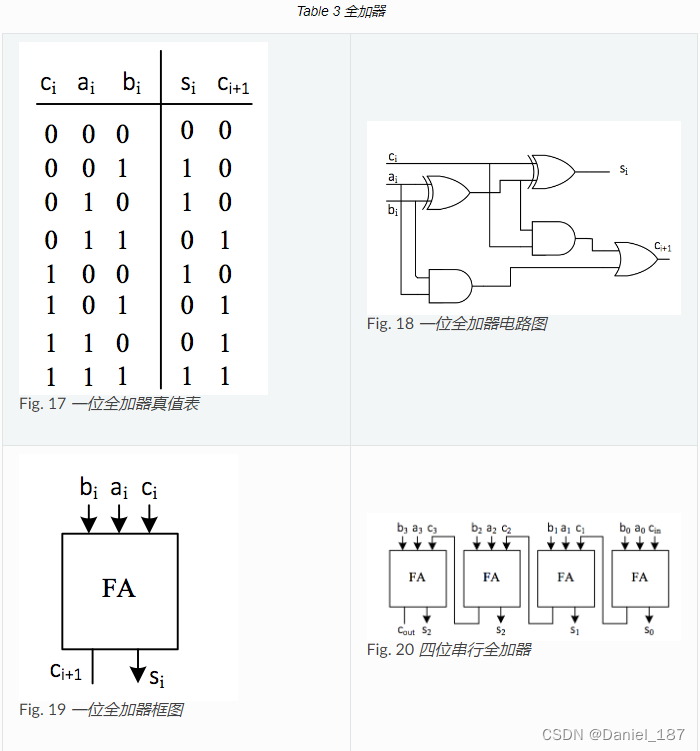
八位加法器实现
上述四位串行加法器的设计,如果推广到更多位加法器的设计,程序代码将会变得异常复杂,运行效率也将很低。在Verilog语言中,可以使用算术赋值语句和向量来执行这种算术运算。如果我们定义如下向量:
input  [n-1:0]  in_x, in_y;
output [n-1:0]  out_s;
则算术赋值语句
out_s = in_x + in_y;
就可以实现n位加法器了。
请注意,该代码定义了可以生成n位加法器的电路,但是该加法器电路并不包含加法过程中产生的进位输出信号和算术溢出信号。
溢出信号是用于判断运算结果 out_s 是否正确的信号。可以证明,对于有符号的补码运算的算术溢出信号可以用下面的表达式得到:
O v e r f l o w = ( i n _ x n − 1 = = i n _ y n − 1 ) & & ( o u t _ s n − 1 ! = i n _ x n − 1 ) Overflow=(in\_x_{n-1} == in\_y_{n-1})\&\&(out\_s_{n-1} != in\_x_{n-1}) Overflow=(in_xn−1==in_yn−1)&&(out_sn−1!=in_xn−1)
其判断原理是:如果两个参加加法运算的变量符号相同,而运算结果的符号与其不相同,则运算结果不准确,产生溢出
对于进位信号可以用下面的表达式得到:
{out_c,out_s} =in_x + in_y;
此表达式执行后, out_c 即为进位位, out_s 即为加法运算结果,这里的进位位仅用于表示在加法运算过程中,操作数的最高位是否对外有进位,和X86体系中借位CF的概念在减法操作中是相反的,即X86中的
C
F
=
o
u
t
c
⊕
c
i
n
CF=out_c\oplus cin
CF=outc⊕cin ,其中 cin 在减法时置1。在有符号的加减法中,溢出判断依据为溢出位,进位位不用。而在无符号数的加减法中,溢出判断依据进位位,溢出位不用
简单加减法运算器的设计
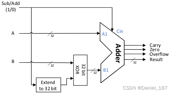
两个32位的参与运算的数据的补码操作数A和操作数B,一个控制做加法还是做减法的加/减控制端Sub/Add,为1时进行减法运算。输出信号有:一个32位的结果Result、一位进位位,一位溢出位和一位判断结果是否为零的输出位。
在图中已经加入了对减数进行求补操作,将减法变成加法的过程。即:如A – B,可以先求出(– B)的值,然后再和A相加,即A – B = A +(–B)。对于补码而言,– B的补码就是将B连同符号位在内全部取反再加一的过程。