参考:https://blog.csdn.net/qq_38427678/article/details/94607733
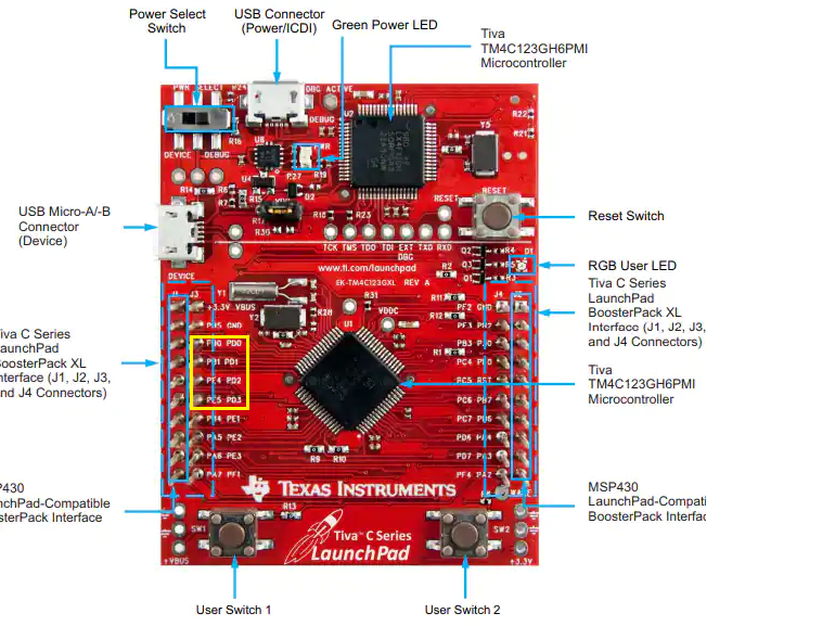
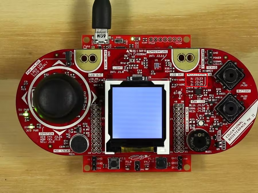
各个pin口连接方式如下:
// J1 J3 J4 J2
// [ 1] [21] [40] [20]
// [ 2] [22] [39] [19]
// [ 3] [23] [38] [18]
// [ 4] [24] [37] [17]
// [ 5] [25] [36] [16]
// [ 6] [26] [35] [15]
// [ 7] [27] [34] [14]
// [ 8] [28] [33] [13]
// [ 9] [29] [32] [12]
// [10] [30] [31] [11]
// accelerometer 黄色所示
// J3.23 accelerometer X (analog) {TM4C123 PD0/AIN7, MSP432 P6.1}
// J3.24 accelerometer Y (analog) {TM4C123 PD1/AIN6, MSP432 P4.0}
// J3.25 accelerometer Z (analog) {TM4C123 PD2/AIN5, MSP432 P4.2}
adcinit初始化:
// accelerometer X (J3.23/PD0/AIN7), Y (J3.24/PD1/AIN6), and Z (J3.25/PD2/AIN5)
void static adcinit(void){
SYSCTL_RCGCADC_R |= 0x00000001; // 1) //使能ADC0外设
while((SYSCTL_PRADC_R&0x01) == 0){};// 2) 等待
ADC0_PC_R &= ~0xF; // 8) clear max sample rate field
ADC0_PC_R |= 0x1; // configure for 125K samples/sec
ADC0_SSPRI_R = 0x3210; // 9) Sequencer 3 is lowest priority
}
BSP_Accelerometer_Init
// BoosterPack pins J3.23 (X), J3.24 (Y), and// J3.25 (Z).
void BSP_Accelerometer_Init(void){
adcinit();
SYSCTL_RCGCGPIO_R |= 0x00000008; // 1)Port D时钟配置
while((SYSCTL_PRGPIO_R&0x08) == 0){};//2)等待
GPIO_PORTD_AMSEL_R |= 0x07; // 3) 配置ADC0的IO脚 PD2-0为模拟脚
GPIO_PORTD_DIR_R &= ~0x07; // 5) 设置为输入模式
GPIO_PORTD_AFSEL_R |= 0x07; // 6) 设置多路复用功能为adc(不用其他功能)
GPIO_PORTD_DEN_R &= ~0x07; // 7) 使能adc PD2-0 禁止它的数字功能,启用为模拟功能
adcinit(); // 8-9) ADC 初始化
ADC0_ACTSS_R &= ~0x0004; // 10) 暂时禁止采样序列sample sequencer 2
ADC0_EMUX_R &= ~0x0F00; // 11) 采样序列sample sequencer 2为软件触发模式
ADC0_SSMUX2_R = 0x0567; // 12) 设置序列sample sequencer 2
ADC0_SSCTL2_R = 0x0600; // 13) 编程到最后一个半字节时 确定END bit置位(ADC_CTL_END) 否者 导致 不可预测错误
ADC0_IM_R &= ~0x0004; // 14) disable SS2 interrupts 清除中断状态标志。这样做是为了确保,中 断标志在我们采样之前被清除
ADC0_ACTSS_R |= 0x0004; // 15) enable sample sequencer 2使能采样序列
}
3. BSP_Accelerometer_Input
void BSP_Accelerometer_Input(uint16_t *x, uint16_t *y, uint16_t *z){
ADC0_PSSI_R = 0x0004; // 1) initiate SS2
while((ADC0_RIS_R&0x04)==0){}; // 2) wait for conversion done
*x = ADC0_SSFIFO2_R>>2; // 3a) read first result
*y = ADC0_SSFIFO2_R>>2; // 3b) read second result
*z = ADC0_SSFIFO2_R>>2; // 3c) read third result
ADC0_ISC_R = 0x0004; // 4) acknowledge completion
}
