RK3576是RK今年上市的中高端旗舰芯片,定位弱于RK3588。这篇文章主要分享一下RK3576这颗主控芯片的camera资源。
(1)RK3576 camera资源
①RK3576 camera硬件框图
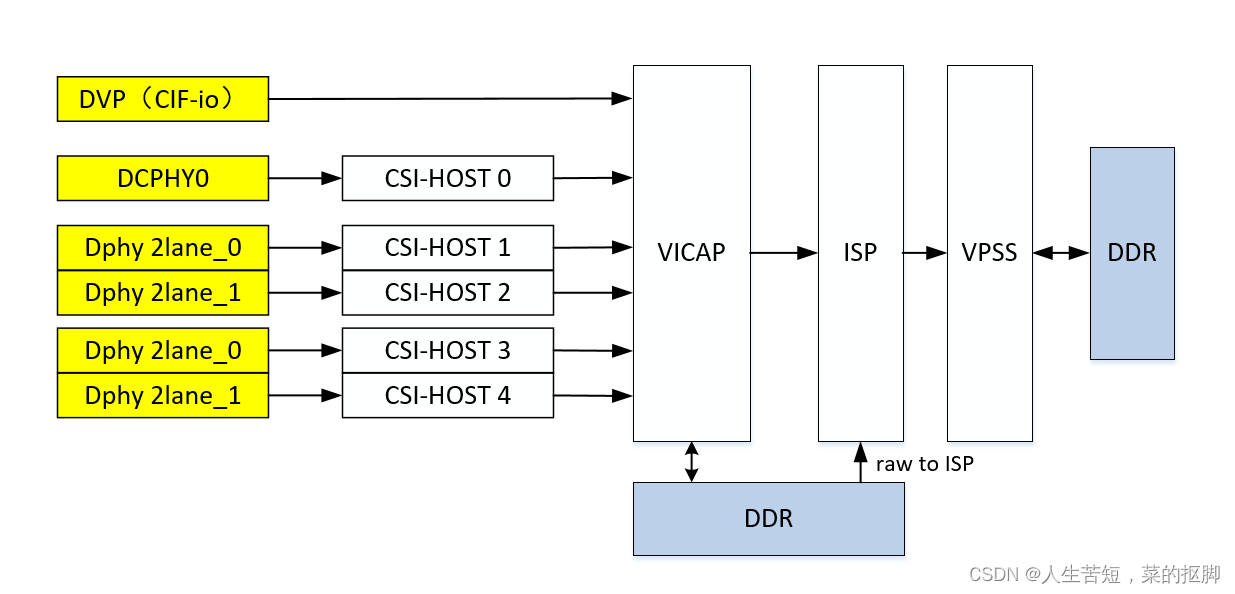
RK3576的camera硬件框图如图所示,拥有一路4lane的DCPHY,2路4lane的DPHY,可以拆分成4路2lane的模式,还有一路DVP并口,可以支持BT1120/BT656/BT601接口视频数据。有一个ISP控制器。
②MIPI-CSI资源
RK3576 MIPI-CSI资源如下,有1路DCPHY,2路DPHY,其中2路DPHY都可以拆成2lane+2lane的模式使用,共计5个MIPI-CSI HOST,可支持接入5个MIPI camera设备,2lane的场景,最大带宽为5G/bps,4lane场景,最大带宽为10Gbps,YUV422的图像输入的话,例如HDMIIN转接芯片,可以支持到4K60。DCPHY可以作为DPHY 4lane输入也可以作为CPHY 3trios输入,CPHY的场景带宽可达到17Gbps。
| type | MAX bandwidth | num | mode | |
| DPHY | DPHY-v1.2 | 2.5Gbps/lane | 2 | 4lane or 2lane+2lane |
| DCPHY | DPHY-v2.0 or CPHY-v1.1 | 2.5Gbps/lane 2.5Gsps/trios | 1 | DPHY or CPHY |
③VICAP资源
| 接口 | 数量 | 输入 | 输出 |
| vicap | 5个MIPI 1个DVP | MIPI CSI: RAW8/10/12/14/16, RGB888, YUV422 8bit, YUV422 8bit interlaced, YUV420 8bit, Legacy YUV420 8bit DVP:BT.601 RAW8/10/12 YCbCr 422 8-bit input BT.656 YCbCr 422 8-bit progressive/interlaced input BT.1120 YCbCr 422 8-bit progressive/interlaced input | NV16/NV12/YUV400/YUYV 紧凑/非紧凑 RAW RGB888 |
④ISP资源
| 工作模式 | 吞吐率 | 最大分辨率 | 输入格式 |
| 单cis | 16M@30fps 48M@10fps | 4672x3504 8064x6048 | VICAP: raw8/raw10/raw12 |
⑤VPSS
看RK3576的描述,在ISP后级应该还有VPSS模块,可以做图像处理,但是目前RK官方似乎也没有描述RK3576该模块的功能以及使用方法。以下是网上海思VPSS模块的描述。
根据网上对海思VPSS模块的描述:VPSS(Video Process Sub-System)支持对一幅输入图像进行统一预处理,如去噪、去隔行等,然后再对各通道分别进行缩放、锐化等处理,最后输出多种不同分辨率的图像。
根据RK的描述,应该是可以支持旋转镜像裁减多路输出等功能。

⑥最多支持camera数量
RK3576最多可以支持5个MIPIcamera,一个DVP的camera,对应链接框图如下,两路DPHY分别使用2lane+2lane的方式,如果是YUV的sensor,仅需要链接到rkcif_mipi_lvds节点即可,不需要接到stdif虚拟节点。

若采用4lane的方式链接如下:

(2)dts配置
根据上述,RK3576至多可以同时接入5路 MIPI摄像头,下篇文章再介绍。可参考如下:
&csi2_dcphy0 {
	status = "okay";

	ports {
		#address-cells = <1>;
		#size-cells = <0>;
		port@0 {
			reg = <0>;
			#address-cells = <1>;
			#size-cells = <0>;

			mipi_in_gc05a2: endpoint@1 {
				reg = <1>;
				remote-endpoint = <&gc05a2_out0>;
				data-lanes = <1 2 3 4>;
			};

		};
		port@1 {
			reg = <1>;
			#address-cells = <1>;
			#size-cells = <0>;

			csidcphy0_out: endpoint@0 {
				reg = <0>;
				remote-endpoint = <&mipi0_csi2_input>;
			};
		};
	};
};

&csi2_dphy3 {
	status = "okay";

	ports {
		#address-cells = <1>;
		#size-cells = <0>;
		port@0 {
			reg = <0>;
			#address-cells = <1>;
			#size-cells = <0>;

			mipi_in_s5k3l8xx: endpoint@1 {
				reg = <1>;
				remote-endpoint = <&s5k3l8xx_out0>;
				data-lanes = <1 2 3 4>;
			};

			mipi_in_ov16880: endpoint@2 {
				reg = <2>;
				remote-endpoint = <&ov16880_out0>;
				data-lanes = <1 2 3 4>;
			};
		};
		port@1 {
			reg = <1>;
			#address-cells = <1>;
			#size-cells = <0>;

			csidphy3_out: endpoint@0 {
				reg = <0>;
				remote-endpoint = <&mipi3_csi2_input>;
			};
		};
	};
};

&csi2_dphy0_hw {
	status = "okay";
};

&csi2_dphy1_hw {
	status = "okay";
};

&i2c4 {
	status = "okay";
	pinctrl-0 = <&i2c4m3_xfer>;

	gc05a2: gc05a2@37 {
		compatible = "galaxycore,gc05a2";
		status = "okay";
		reg = <0x37>;
		clocks = <&cru CLK_MIPI_CAMERAOUT_M0>;
		clock-names = "xvclk";
		pinctrl-names = "default";
		pinctrl-0 = <&cam_clk0m0_clk0>;
		pwdn-gpios = <&gpio3 RK_PC7 GPIO_ACTIVE_HIGH>;
		reset-gpios = <&gpio3 RK_PA6 GPIO_ACTIVE_HIGH>;
		avdd-supply = <&vcc_mipipwr>;
		dovdd-supply = <&vcc_1v8_cam>;
		//dvdd-supply = <&vcc1v2_dvp>;
		rockchip,camera-module-index = <1>;
		rockchip,camera-module-facing = "front";
		rockchip,camera-module-name = "KYT-11210-V2";
		rockchip,camera-module-lens-name = "default";
		port {
			gc05a2_out0: endpoint {
				remote-endpoint = <&mipi_in_gc05a2>;
				data-lanes = <1 2>;
			};
		};
	};
};

&i2c5 {
	status = "okay";
	pinctrl-names = "default";
	pinctrl-0 = <&i2c5m3_xfer>;

	ces6301: ces6301@c {
		compatible = "chipextra,ces6301";
		status = "okay";
		reg = <0x0c>;
		avdd-supply = <&vcc_mipipwr>;
		rockchip,vcm-max-current = <120>;
		rockchip,vcm-start-current = <10>;
		rockchip,vcm-rated-current = <85>;
		rockchip,vcm-step-mode = <9>;
		rockchip,camera-module-index = <0>;
		rockchip,camera-module-facing = "back";
	};

	s5k3l8xx: s5k3l8xx@10 {
		status = "okay";
		compatible = "samsung,s5k3l8xx";
		reg = <0x10>;
		clocks = <&cru CLK_MIPI_CAMERAOUT_M2>;
		clock-names = "xvclk";
		pinctrl-names = "default";
		pinctrl-0 = <&cam_clk2m0_clk2>;
		pwdn-gpios = <&gpio3 RK_PD5 GPIO_ACTIVE_HIGH>;
		reset-gpios = <&gpio3 RK_PA7 GPIO_ACTIVE_HIGH>;
		avdd-supply = <&vcc_mipipwr>;
		dovdd-supply = <&vcc_1v8_cam>;
		//dvdd-supply = <&vcc1v2_dvp>;
		rockchip,camera-module-index = <0>;
		rockchip,camera-module-facing = "back";
		rockchip,camera-module-name = "KYT-11097-B-V1";
		rockchip,camera-module-lens-name = "default";
		lens-focus = <&ces6301>;
		flash-leds = <&flash_rgb13h>;
		port {
			s5k3l8xx_out0: endpoint {
				remote-endpoint = <&mipi_in_s5k3l8xx>;
				data-lanes = <1 2 3 4>;
			};
		};
	};

	ov16880: ov16880@36 {
		status = "okay";
		compatible = "ovti,ov16880";
		reg = <0x36>;
		clocks = <&cru CLK_MIPI_CAMERAOUT_M2>;
		clock-names = "xvclk";
		pinctrl-names = "default";
		pinctrl-0 = <&cam_clk2m0_clk2>;
		pwdn-gpios = <&gpio3 RK_PD5 GPIO_ACTIVE_HIGH>;
		reset-gpios = <&gpio3 RK_PA7 GPIO_ACTIVE_HIGH>;
		avdd-supply = <&vcc_mipipwr>;
		dovdd-supply = <&vcc_1v8_cam>;
		//dvdd-supply = <&vcc1v2_dvp>;
		rockchip,camera-module-index = <0>;
		rockchip,camera-module-facing = "back";
		rockchip,camera-module-name = "KYT-11379-V1";
		rockchip,camera-module-lens-name = "default";
		lens-focus = <&ces6301>;
		flash-leds = <&flash_rgb13h>;
		port {
			ov16880_out0: endpoint {
				remote-endpoint = <&mipi_in_ov16880>;
				data-lanes = <1 2 3 4>;
			};
		};
	};
};

&mipi0_csi2 {
	status = "okay";

	ports {
		#address-cells = <1>;
		#size-cells = <0>;

		port@0 {
			reg = <0>;
			#address-cells = <1>;
			#size-cells = <0>;

			mipi0_csi2_input: endpoint@1 {
				reg = <1>;
				remote-endpoint = <&csidcphy0_out>;
			};
		};

		port@1 {
			reg = <1>;
			#address-cells = <1>;
			#size-cells = <0>;

			mipi0_csi2_output: endpoint@0 {
				reg = <0>;
				remote-endpoint = <&cif_mipi_in0>;
			};
		};
	};
};

&mipi3_csi2 {
	status = "okay";

	ports {
		#address-cells = <1>;
		#size-cells = <0>;

		port@0 {
			reg = <0>;
			#address-cells = <1>;
			#size-cells = <0>;

			mipi3_csi2_input: endpoint@1 {
				reg = <1>;
				remote-endpoint = <&csidphy3_out>;
			};
		};

		port@1 {
			reg = <1>;
			#address-cells = <1>;
			#size-cells = <0>;

			mipi3_csi2_output: endpoint@0 {
				reg = <0>;
				remote-endpoint = <&cif_mipi3_in0>;
			};
		};
	};
};

&pinctrl {
	cam {
		mipicam_pwr: mipicam-pwr {
			rockchip,pins =
				/* camera power en */
				<3 RK_PC6 RK_FUNC_GPIO &pcfg_pull_none>;
		};

		flash_led_gpios: flash-led {
			rockchip,pins =
				/* flash led enable */
				<2 RK_PD5 RK_FUNC_GPIO &pcfg_pull_none>;
		};
	};
};

&rkcif {
	status = "okay";
};

&rkcif_mipi_lvds {
	status = "okay";

	port {
		cif_mipi_in0: endpoint {
			remote-endpoint = <&mipi0_csi2_output>;
		};
	};
};

&rkcif_mipi_lvds_sditf {
	status = "okay";

	port {
		mipi_lvds_sditf: endpoint {
			remote-endpoint = <&isp_vir0_in0>;
		};
	};
};

&rkcif_mipi_lvds3 {
	status = "okay";

	port {
		cif_mipi3_in0: endpoint {
			remote-endpoint = <&mipi3_csi2_output>;
		};
	};
};

&rkcif_mipi_lvds3_sditf {
	status = "okay";

	port {
		mipi_lvds3_sditf: endpoint {
			remote-endpoint = <&isp_vir0_in1>;
		};
	};
};

&rkcif_mmu {
	status = "okay";
};

&rkisp {
	status = "okay";
};

&rkisp_mmu {
	status = "okay";
};

&rkisp_vir0 {
	status = "okay";

	port {
		#address-cells = <1>;
		#size-cells = <0>;

		isp_vir0_in0: endpoint@0 {
			reg = <0>;
			remote-endpoint = <&mipi_lvds_sditf>;
		};

		isp_vir0_in1: endpoint@1 {
			reg = <1>;
			remote-endpoint = <&mipi_lvds3_sditf>;
		};
	};
};
(3)总结
后续继续介绍详细的dts配置以及调试经验。


