1 前言
除了Reset(优先级-3),NMI(优先级-2) 和 HardFault(优先级-1)三个异常的有限制为固定值外,对于其他优先级可配置的异常,Cortex-M7最大支持0~255共计256个优先级。具体支持的优先级范围,决定于芯片厂商的实现,通常都会进行裁剪。
总的来说,Cortex-M7对于异常的优先级有着如下规定:
① 优先级值越小,表示的优先级越高;
② 除了Reset,NMI和HardFault外,其他异常的优先级均是可配置的;
③ 若多个优先级相同的异常同时被悬起(pending,都处于等待CPU响应阶段),则其中异常号较小的异常优先被响应;例如,如果IRQ[0] 和 IRQ[1] 同时悬起,且两者优先级相同,则IRQ[0]会被优先响应;
④ 当CPU正在处理一个异常时(正在执行对应ISR),如果由更高优先级的异常到来,则会被抢占;如果有相同优先级的异常到来,则不会发生抢占(这与新来异常的异常号无关),同时,这个同优先级的新到异常会被悬起,进入pending状态。
所以,Reset,NMI和HardFault的优先级注定高于其他异常。
2 中断优先级相关寄存器

图1 中断向量表
2.1 系统异常优先级寄存器(System Handler Priority Registers)
如图1所示,Cortex-M7对异常号为1~6和11,14,15的系统异常都有明确的定义,这样包括了它们的异常优先级。由于需要最大支持0~255共计256个优先级,除去Reset,NMI和HardFault三个优先级为固定值的异常外,每个优先级都是通过寄存器SHPR1-SHPR3中对应的的8个bit来配置的,具体分布情况见表1。
表1 系统异常优先级分布
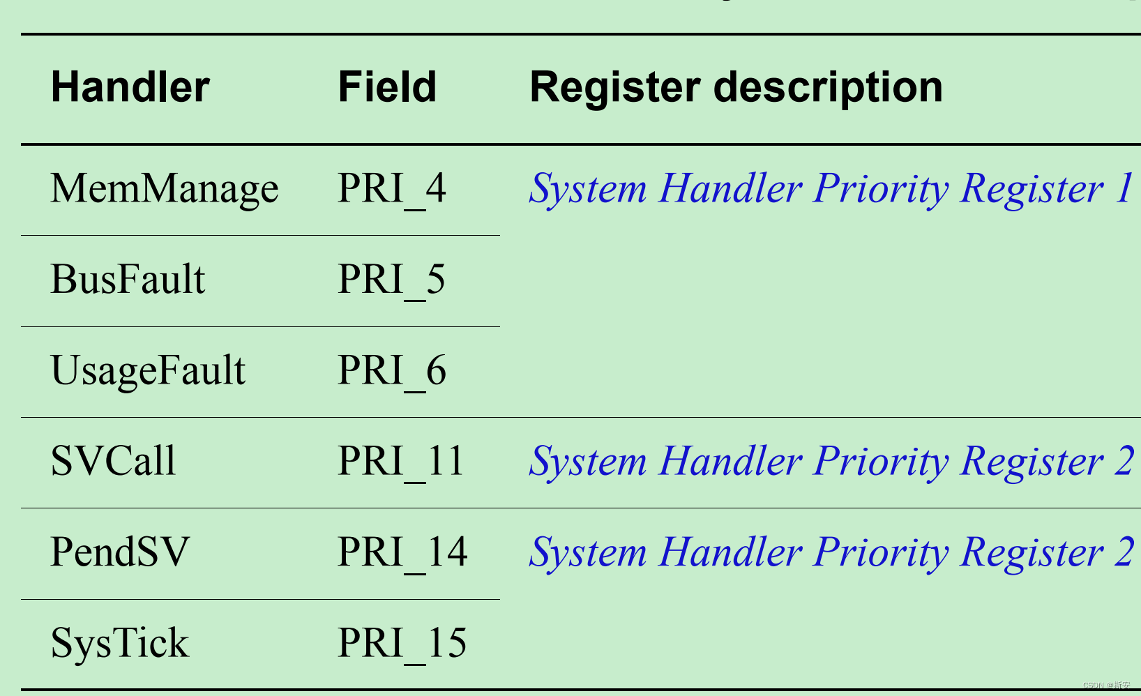
SHPR1-SHPR3寄存器是按字节分布的,最多8bit有效,根据具体的实现不同,会按高位对齐进行裁剪。例如,bits[7:M]为有效位,Bits[M-1:0]读回0,写无效。当M为4时,则支持最大16个优先级,Bits[3:0]为预留位。按高位对齐的好处是,便于软件的移植,不会出现MSB丢失导致优先级翻转的情况出现。
2.1.1 System Handler Priority Register 1

图2 系统异常优先级寄存器1
系统异常优先级寄存器1位域分布见图2,具体的含义见表2:
表2 系统异常优先级寄存器1含义

2.1.2 System Handler Priority Register 2
对应的位域分布和含义见图3和表3:
![]()
图3 系统异常优先级寄存器2
表3 系统异常优先级寄存器2含义

2.1.3 System Handler Priority Register 3
对应的位域分布和含义见图4和表4:
![]()
图4 系统异常优先级寄存器3
表4 系统异常优先级寄存器3含义

2.2 外部中断优先级寄存器
可以通过NVIC_IPR0-NVIC_IPR59共计60个寄存器为240个外部中断指定优先级。同样,每个中断的优先级由寄存器中的8个bit来定义,其分布如图5所示:

图5 外部中断优先级寄存器位域分布
与系统异常的优先级相同,每个外部中断的优先级最多8bit有效,根据具体的实现不同,会按高位对齐进行裁剪。而检测有多少个位用于优先级定义也很简单,只要向对应8bit写入0xFF并回读,成功置位为1的位数即是用于优先级配置的位数。
2.3 异常(中断)优先级相关的CMSIS接口
typedef struct
{
  __IOM uint32_t ISER[8U];               /*!< Offset: 0x000 (R/W)  Interrupt Set Enable Register */
        uint32_t RESERVED0[24U];
  __IOM uint32_t ICER[8U];               /*!< Offset: 0x080 (R/W)  Interrupt Clear Enable Register */
        uint32_t RESERVED1[24U];
  __IOM uint32_t ISPR[8U];               /*!< Offset: 0x100 (R/W)  Interrupt Set Pending Register */
        uint32_t RESERVED2[24U];
  __IOM uint32_t ICPR[8U];               /*!< Offset: 0x180 (R/W)  Interrupt Clear Pending Register */
        uint32_t RESERVED3[24U];
  __IOM uint32_t IABR[8U];               /*!< Offset: 0x200 (R/W)  Interrupt Active bit Register */
        uint32_t RESERVED4[56U];
  __IOM uint8_t  IP[240U];               /*!< Offset: 0x300 (R/W)  Interrupt Priority Register (8Bit wide) */
        uint32_t RESERVED5[644U];
  __OM  uint32_t STIR;                   /*!< Offset: 0xE00 ( /W)  Software Trigger Interrupt Register */
}  NVIC_Type;

typedef struct
{
  __IM  uint32_t CPUID;                  /*!< Offset: 0x000 (R/ )  CPUID Base Register */
  __IOM uint32_t ICSR;                   /*!< Offset: 0x004 (R/W)  Interrupt Control and State Register */
  __IOM uint32_t VTOR;                   /*!< Offset: 0x008 (R/W)  Vector Table Offset Register */
  __IOM uint32_t AIRCR;                  /*!< Offset: 0x00C (R/W)  Application Interrupt and Reset Control Register */
  __IOM uint32_t SCR;                    /*!< Offset: 0x010 (R/W)  System Control Register */
  __IOM uint32_t CCR;                    /*!< Offset: 0x014 (R/W)  Configuration Control Register */
  __IOM uint8_t  SHPR[12U];              /*!< Offset: 0x018 (R/W)  System Handlers Priority Registers (4-7, 8-11, 12-15) */
  __IOM uint32_t SHCSR;                  /*!< Offset: 0x024 (R/W)  System Handler Control and State Register */
  __IOM uint32_t CFSR;                   /*!< Offset: 0x028 (R/W)  Configurable Fault Status Register */
  __IOM uint32_t HFSR;                   /*!< Offset: 0x02C (R/W)  HardFault Status Register */
  __IOM uint32_t DFSR;                   /*!< Offset: 0x030 (R/W)  Debug Fault Status Register */
  __IOM uint32_t MMFAR;                  /*!< Offset: 0x034 (R/W)  MemManage Fault Address Register */
  __IOM uint32_t BFAR;                   /*!< Offset: 0x038 (R/W)  BusFault Address Register */
  __IOM uint32_t AFSR;                   /*!< Offset: 0x03C (R/W)  Auxiliary Fault Status Register */
  __IM  uint32_t ID_PFR[2U];             /*!< Offset: 0x040 (R/ )  Processor Feature Register */
  __IM  uint32_t ID_DFR;                 /*!< Offset: 0x048 (R/ )  Debug Feature Register */
  __IM  uint32_t ID_AFR;                 /*!< Offset: 0x04C (R/ )  Auxiliary Feature Register */
  __IM  uint32_t ID_MFR[4U];             /*!< Offset: 0x050 (R/ )  Memory Model Feature Register */
  __IM  uint32_t ID_ISAR[5U];            /*!< Offset: 0x060 (R/ )  Instruction Set Attributes Register */
        uint32_t RESERVED0[1U];
  __IM  uint32_t CLIDR;                  /*!< Offset: 0x078 (R/ )  Cache Level ID register */
  __IM  uint32_t CTR;                    /*!< Offset: 0x07C (R/ )  Cache Type register */
  __IM  uint32_t CCSIDR;                 /*!< Offset: 0x080 (R/ )  Cache Size ID Register */
  __IOM uint32_t CSSELR;                 /*!< Offset: 0x084 (R/W)  Cache Size Selection Register */
  __IOM uint32_t CPACR;                  /*!< Offset: 0x088 (R/W)  Coprocessor Access Control Register */
        uint32_t RESERVED3[93U];
  __OM  uint32_t STIR;                   /*!< Offset: 0x200 ( /W)  Software Triggered Interrupt Register */
        uint32_t RESERVED4[15U];
  __IM  uint32_t MVFR0;                  /*!< Offset: 0x240 (R/ )  Media and VFP Feature Register 0 */
  __IM  uint32_t MVFR1;                  /*!< Offset: 0x244 (R/ )  Media and VFP Feature Register 1 */
  __IM  uint32_t MVFR2;                  /*!< Offset: 0x248 (R/ )  Media and VFP Feature Register 2 */
        uint32_t RESERVED5[1U];
  __OM  uint32_t ICIALLU;                /*!< Offset: 0x250 ( /W)  I-Cache Invalidate All to PoU */
        uint32_t RESERVED6[1U];
  __OM  uint32_t ICIMVAU;                /*!< Offset: 0x258 ( /W)  I-Cache Invalidate by MVA to PoU */
  __OM  uint32_t DCIMVAC;                /*!< Offset: 0x25C ( /W)  D-Cache Invalidate by MVA to PoC */
  __OM  uint32_t DCISW;                  /*!< Offset: 0x260 ( /W)  D-Cache Invalidate by Set-way */
  __OM  uint32_t DCCMVAU;                /*!< Offset: 0x264 ( /W)  D-Cache Clean by MVA to PoU */
  __OM  uint32_t DCCMVAC;                /*!< Offset: 0x268 ( /W)  D-Cache Clean by MVA to PoC */
  __OM  uint32_t DCCSW;                  /*!< Offset: 0x26C ( /W)  D-Cache Clean by Set-way */
  __OM  uint32_t DCCIMVAC;               /*!< Offset: 0x270 ( /W)  D-Cache Clean and Invalidate by MVA to PoC */
  __OM  uint32_t DCCISW;                 /*!< Offset: 0x274 ( /W)  D-Cache Clean and Invalidate by Set-way */
        uint32_t RESERVED7[6U];
  __IOM uint32_t ITCMCR;                 /*!< Offset: 0x290 (R/W)  Instruction Tightly-Coupled Memory Control Register */
  __IOM uint32_t DTCMCR;                 /*!< Offset: 0x294 (R/W)  Data Tightly-Coupled Memory Control Registers */
  __IOM uint32_t AHBPCR;                 /*!< Offset: 0x298 (R/W)  AHBP Control Register */
  __IOM uint32_t CACR;                   /*!< Offset: 0x29C (R/W)  L1 Cache Control Register */
  __IOM uint32_t AHBSCR;                 /*!< Offset: 0x2A0 (R/W)  AHB Slave Control Register */
        uint32_t RESERVED8[1U];
  __IOM uint32_t ABFSR;                  /*!< Offset: 0x2A8 (R/W)  Auxiliary Bus Fault Status Register */
} SCB_Type;

/**
  \brief   Set Interrupt Priority
  \details Sets the priority of a device specific interrupt or a processor exception.
           The interrupt number can be positive to specify a device specific interrupt,
           or negative to specify a processor exception.
  \param [in]      IRQn  Interrupt number.
  \param [in]  priority  Priority to set.
  \note    The priority cannot be set for every processor exception.

  __IOM uint8_t  IP[240U];    /*!< Offset: 0x300 (R/W)  Interrupt Priority Register (8Bit wide) */

  __IOM uint8_t  SHPR[12U];   /*!< Offset: 0x018 (R/W)  System Handlers Priority Registers (4-7, 8-11, 12-15) */

 */
__STATIC_INLINE void __NVIC_SetPriority(IRQn_Type IRQn, uint32_t priority)
{
  if ((int32_t)(IRQn) >= 0)
  {
    NVIC->IP[((uint32_t)IRQn)]                = (uint8_t)((priority << (8U - __NVIC_PRIO_BITS)) & (uint32_t)0xFFUL);
  }
  else
  {
    SCB->SHPR[(((uint32_t)IRQn) & 0xFUL)-4UL] = (uint8_t)((priority << (8U - __NVIC_PRIO_BITS)) & (uint32_t)0xFFUL);
  }
}

/**
  \brief   Get Interrupt Priority
  \details Reads the priority of a device specific interrupt or a processor exception.
           The interrupt number can be positive to specify a device specific interrupt,
           or negative to specify a processor exception.
  \param [in]   IRQn  Interrupt number.
  \return             Interrupt Priority.
                      Value is aligned automatically to the implemented priority bits of the microcontroller.
 */
__STATIC_INLINE uint32_t __NVIC_GetPriority(IRQn_Type IRQn)
{

  if ((int32_t)(IRQn) >= 0)
  {
    return(((uint32_t)NVIC->IP[((uint32_t)IRQn)]                >> (8U - __NVIC_PRIO_BITS)));
  }
  else
  {
    return(((uint32_t)SCB->SHPR[(((uint32_t)IRQn) & 0xFUL)-4UL] >> (8U - __NVIC_PRIO_BITS)));
  }
}
其中,IRQn为异常号,__NVIC_PRIO_BITS为对应优先级寄存器的有效位数,按高位对齐。
2.4 中断优先级分组
中断优先级分组,主要是为了提供更细腻的中断优先级控制,该控制主要体现在优先级抢占的具体行为上。
如前文所述,高优先级的异常可以无条件的打断并抢占低优先级异常的执行;另一方面,当多个相同优先级的中断进入pending状态时,异常号小的异常会被优先级响应,而一旦进入异常处理阶段(ISR开始执行),后来的相同优先级的异常是无法进行抢占的,无论其异常号是多少。后一个机制在pending时根据异常号来决定CPU优先响应的异常,这毕竟和异常号耦合在了一起。而优先级分组避免了这个问题,让用户可以通过分组来实现类似的机制。具体来说:
① 将定义优先级的位域的高位用于定义分组(抢占)优先级(group priority),这个优先级值直接影响到抢占行为,可以称之为主优先级或分组优先级;
② 将定义优先级的位域的低位用于定义组内异常子优先级;
分组优先级相同的中断无法互相抢占,但当多个分组优先级相同的异常处于pending状态时,子优先级决定了CPU对它们的处理顺序,即子优先级高的异常优先受到响应。
2.4.1 Application Interrupt and Reset Control Register
AIRCR寄存器提供了优先级分组方式的具体定义,其位域分布如图6:

图6 AIRCR寄存器
向该寄存器写入数据时,必须先向VECTKEY位段写入0x5FA,否则写入数据会被忽略。其中,bit[10:8]为优先级分组划分相关的位域,共3个bit,其具体含义如表5所示:
表5 PRIGROUP位段含义
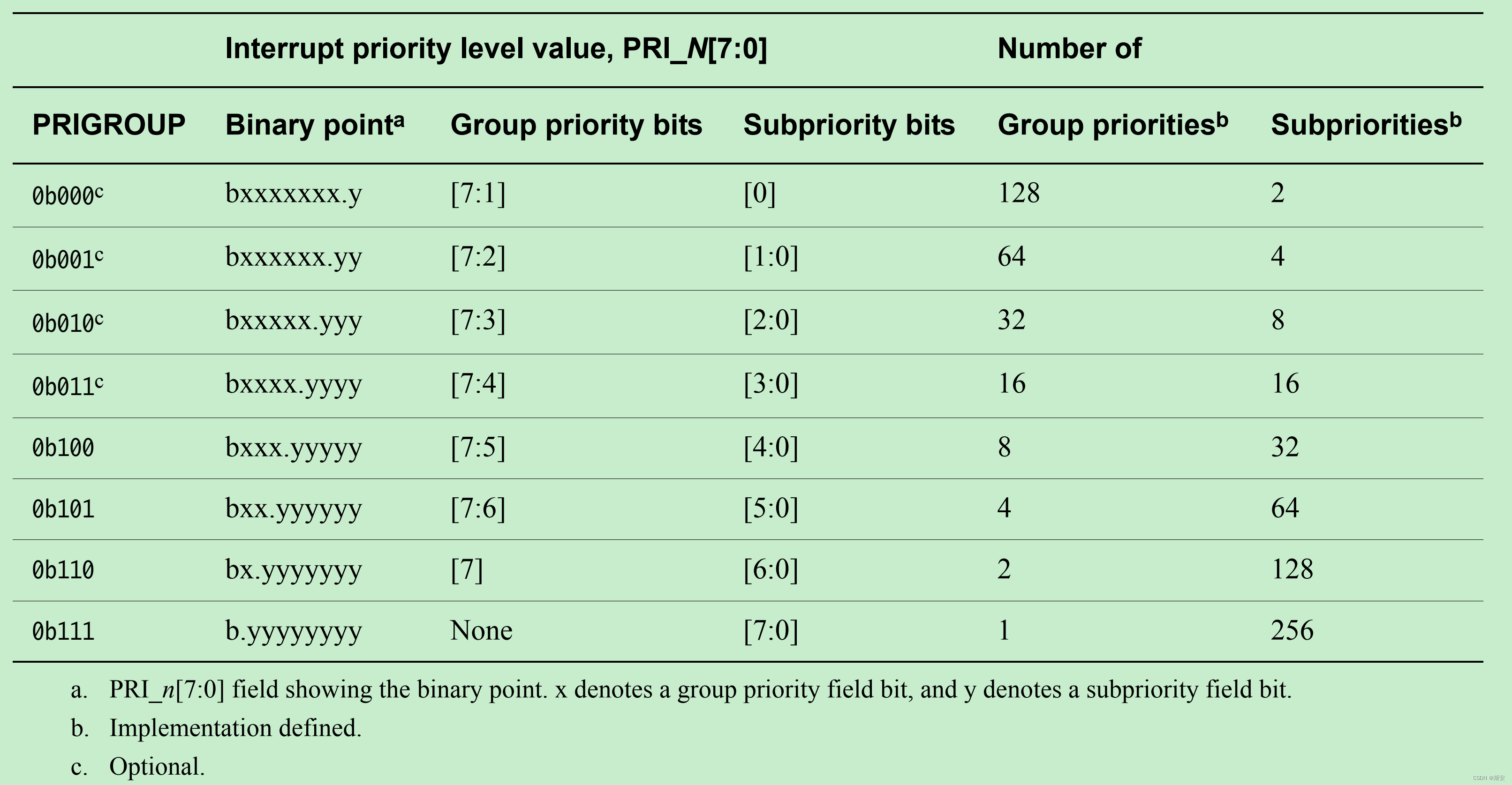
从中可以看出,PRIGROUP的值决定了分组优先级和子优先级在8bit上的分界线。例如,当其值为4时,则bit4及其他低位都用于子优先级的定义,bit[7:5]用于分组优先级的定义。换句话说,(7 - PRIGROUP)的值则是用于分组优先级定义的位数。
CMSIS中优先级分组设置的接口如下(通过写AIRCR寄存器实现):
/**
  \brief   Set Priority Grouping
  \details Sets the priority grouping field using the required unlock sequence.
           The parameter PriorityGroup is assigned to the field SCB->AIRCR [10:8] PRIGROUP field.
           Only values from 0..7 are used.
           In case of a conflict between priority grouping and available
           priority bits (__NVIC_PRIO_BITS), the smallest possible priority group is set.
  \param [in]      PriorityGroup  Priority grouping field.
 */
__STATIC_INLINE void __NVIC_SetPriorityGrouping(uint32_t PriorityGroup)
{
  uint32_t reg_value;
  uint32_t PriorityGroupTmp = (PriorityGroup & (uint32_t)0x07UL);             /* only values 0..7 are used          */

  reg_value  =  SCB->AIRCR;                                                   /* read old register configuration    */
  reg_value &= ~((uint32_t)(SCB_AIRCR_VECTKEY_Msk | SCB_AIRCR_PRIGROUP_Msk)); /* clear bits to change               */
  reg_value  =  (reg_value                                   |
                ((uint32_t)0x5FAUL << SCB_AIRCR_VECTKEY_Pos) |
                (PriorityGroupTmp << SCB_AIRCR_PRIGROUP_Pos)  );              /* Insert write key and priority group */
  SCB->AIRCR =  reg_value;
}

/**
  \brief   Get Priority Grouping
  \details Reads the priority grouping field from the NVIC Interrupt Controller.
  \return                Priority grouping field (SCB->AIRCR [10:8] PRIGROUP field).
 */
__STATIC_INLINE uint32_t __NVIC_GetPriorityGrouping(void)
{
  return ((uint32_t)((SCB->AIRCR & SCB_AIRCR_PRIGROUP_Msk) >> SCB_AIRCR_PRIGROUP_Pos));
}
最后,通常为了是实现上的简单,多数情况下,都会将所有有效优先级都设置为可抢占优先级,即分组优先级(子优先级所在位并未生效)。

