目录
- 实验条件
- 网络拓朴
- 实验目标
- 开始排错
- 问题1. SW2上的DHCP中继没有配置正确
- 问题2. SW1/SW2的SVI接口被关闭
- 问题3. 安全端口配置了不同的MAC地址
实验条件
网络拓朴
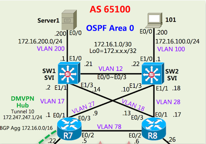
Output1

Output2

实验目标
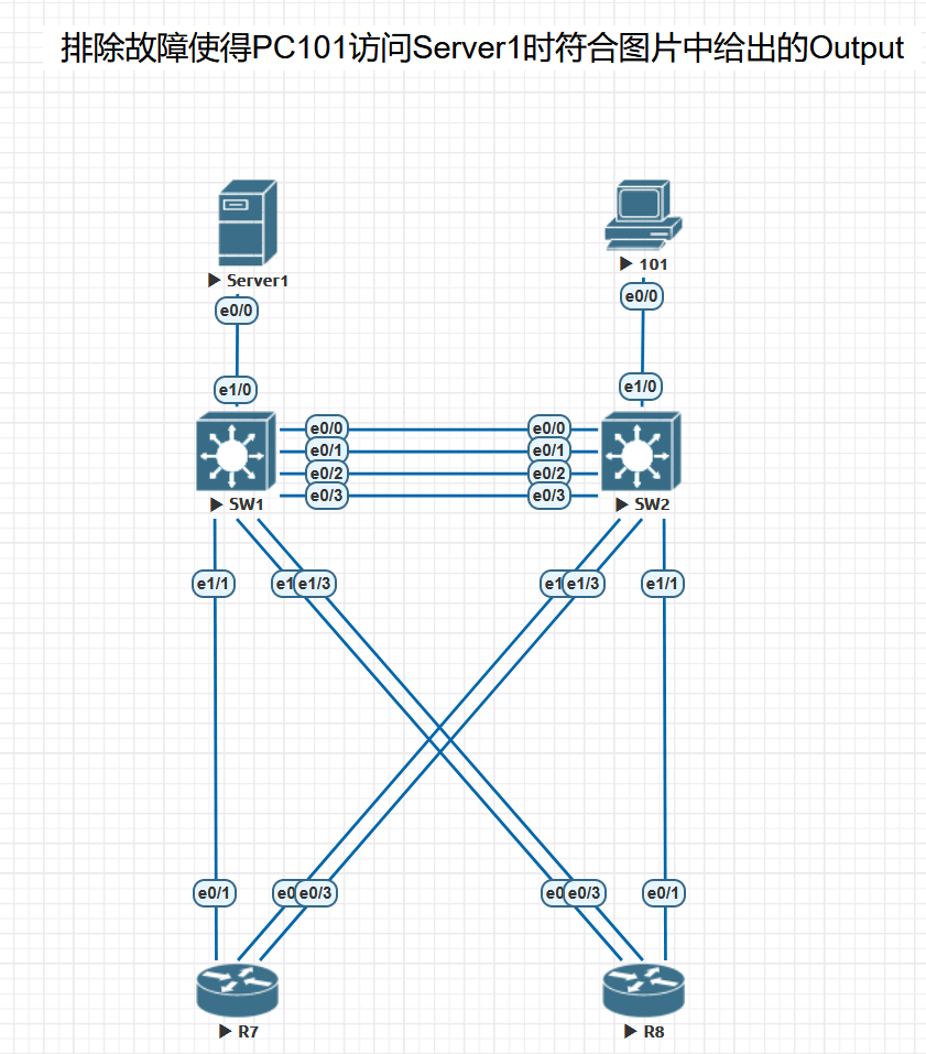
排除故障使得PC101访问Server1时符合图片中给出的Output
开始排错
根据要求,ping对方。
PC101#ping 172.16.200.200
% Unrecognized host or address, or protocol not running.
PC101#show ip route
Default gateway is not set

Host               Gateway           Last Use    Total Uses  Interface
ICMP redirect cache is empty

PC101#show ip int br
Interface                  IP-Address      OK? Method Status                Protocol
Ethernet0/0                unassigned      YES DHCP   up                    up
Ethernet0/1                unassigned      YES TFTP   administratively down down
Ethernet0/2                unassigned      YES TFTP   administratively down down
Ethernet0/3                unassigned      YES TFTP   administratively down down
发现没有获取到IP地址,搜索DHCP服务器
R7#show run | s dhcp
ip dhcp pool Server2
 host 172.16.200.200 255.255.255.0
 client-identifier 01aa.bbcc.002d.00
 default-router 172.16.200.1
 dns-server 172.7.7.7
R7#

R8#show run | s dhcp
ip dhcp pool HOST1
 host 172.16.100.200 255.255.255.0
 client-identifier 01aa.bbcc.0021.11
 dns-server 172.8.8.8
R8#
根据拓扑结构确定PC101是通过R8的DHCP服务器获取到IP地址,由于PC101和我们的R8不是在相同的网络因此需要配置DHCP中继才能让PC获取到IP地址,所以还需要检查交换机上的中继配置,PC101的VLAN100,因此需要在SVI VLAN 100下检查配置,
SW2#show run interface vlan 100
Building configuration...

Current configuration : 124 bytes
!
interface Vlan100
 ip address 172.16.100.1 255.255.255.0
 ip helper-address 172.7.7.7
end
SW2#
发现DHCP中继并没有指向172.8.8.8,因此需要把中继指向R8
问题1. SW2上的DHCP中继没有配置正确
配置上指向R8的中继
SW2#conf t
SW2(config)#int vlan 100
SW2(config-if)#ip helper-address 172.8.8.8
SW2#show run interface vlan 100
Building configuration...

Current configuration : 124 bytes
!
interface Vlan100
 ip address 172.16.100.1 255.255.255.0
 ip helper-address 172.7.7.7
 ip helper-address 172.8.8.8
end
配置成功,现在测试一下Vlan100到R8的172.8.8.8的网络是否连通(没有联通就肯定无法获取IP)
SW2#ping 172.8.8.8 source vlan 100
Type escape sequence to abort.
Sending 5, 100-byte ICMP Echos to 172.8.8.8, timeout is 2 seconds:
Packet sent with a source address of 172.16.100.100
.....
Success rate is 0 percent (0/5)
SW2#
发现无法连接R8的环回口地址,同时检查R8和SW2的VLAN100的SVI接口信息
R8#show ip int br
Interface                  IP-Address      OK? Method Status                Protocol
Ethernet0/0                unassigned      YES TFTP   up                    up
Ethernet0/0.123            123.45.67.26    YES TFTP   up                    up
Ethernet0/0.124            124.45.67.26    YES TFTP   up                    up
Ethernet0/0.125            125.45.67.26    YES TFTP   up                    up
Ethernet0/1                172.16.1.17     YES TFTP   up                    up
Ethernet0/2                172.16.1.6      YES TFTP   up                    up
Ethernet0/3                172.16.1.13     YES TFTP   up                    up
Loopback0                  172.8.8.8       YES TFTP   up                    up
R8#show run interface lo0
Building configuration...

Current configuration : 65 bytes
!
interface Loopback0
 ip address 172.8.8.8 255.255.255.255
end
发现R8并无异常,继续检查SW2的SVI接口
SW2(config)#do show ip int br
Interface              IP-Address      OK? Method Status                Protocol
Ethernet0/0            unassigned      YES unset  up                    up
Ethernet0/1            unassigned      YES unset  up                    up
Ethernet0/2            unassigned      YES unset  up                    up
Ethernet0/3            unassigned      YES unset  up                    up
Ethernet1/0            unassigned      YES unset  up                    up
Ethernet1/1            unassigned      YES unset  up                    up
Ethernet1/2            unassigned      YES unset  up                    up
Ethernet1/3            unassigned      YES unset  up                    up
Loopback0              172.22.22.22    YES NVRAM  up                    up
Vlan10                 unassigned      YES unset  administratively down down
Vlan12                 172.16.1.22     YES NVRAM  administratively down down
Vlan27                 172.16.1.10     YES NVRAM  administratively down down
Vlan28                 172.16.1.18     YES NVRAM  administratively down down
Vlan100                172.16.100.100  YES NVRAM  administratively down down
SW2(config)#
问题2. SW1/SW2的SVI接口被关闭
发现所有的SVI接口都是关闭的、全部打开(一同检查一下SW1,发现也没有打开,全部都打开)
SW1:
	int Vlan12
	no shutdown
	int Vlan17
	no shutdown
	int Vlan18
	no shutdown
	int Vlan100
	no shutdown
	int Vlan200
	no shutdown
SW2:
	int Vlan10
	no shutdown
	int Vlan12
	no shutdown
	int Vlan27
	no shutdown
	int Vlan28
	no shutdown
	int Vlan100
	no shutdown
再次测试与R8之间网络是否连通,还是无法ping通,检查路由。发现Vlan100的IP地址并没有在R8的路由表中,检查路由协议发现,OSPF中宣告的地址是172.16.100.1而且拓扑图上标的也是100.1的IP,而接口上配置却是172.16.100.100,所以需要修改这个IP地址
SW2#show run | s router
router ospf 65100
 router-id 172.22.22.22
 network 172.16.1.10 0.0.0.0 area 0
 network 172.16.1.18 0.0.0.0 area 0
 network 172.16.1.22 0.0.0.0 area 0
 network 172.16.100.1 0.0.0.0 area 0
 network 172.22.22.22 0.0.0.0 area 0
SW2#show ip int br
Interface              IP-Address      OK? Method Status                Protocol
......
Vlan100                172.16.100.100  YES NVRAM  up                    up
SW2#conf t
Enter configuration commands, one per line.  End with CNTL/Z.
SW2(config)#int vlan 100
SW2(config-if)#ip address 172.16.100.1 255.255.255.0
SW2(config-if)#end
SW2#ping 172.8.8.8 source vlan 100
Type escape sequence to abort.
Sending 5, 100-byte ICMP Echos to 172.8.8.8, timeout is 2 seconds:
Packet sent with a source address of 172.16.100.1
!!!!!
Success rate is 100 percent (5/5), round-trip min/avg/max = 1/1/1 ms
SW2#
网络已经通了,关闭PC101的E0/0口再打开。结果还是发现无法获取地址。继续检查SW2和PC101的两个直接接口的配置
SW2(config-if)#do show run
......
interface Ethernet1/0
 switchport access vlan 100
 switchport mode access
 switchport port-security mac-address aabb.cc00.2111
 switchport port-security
 duplex half
!
......

PC101#show run int e0/0
Building configuration...

Current configuration : 128 bytes
!
interface Ethernet0/0
 mac-address aabb.cc00.0000
 ip address dhcp client-id Ethernet0/0
 no ip route-cache
 duplex auto
end

PC101#
发现接口配置了安全端口,绑定了MAC地址,且与PC101不一致
问题3. 安全端口配置了不同的MAC地址
R8服务的地址池分配也是有绑定了MAC地址,这个地址与SW2安全端口绑定的MAC是一致的,为了简单就修改PC101的MAC地址配置
PC101(config-if)#do show run int e0/0
Building configuration...

Current configuration : 128 bytes
!
interface Ethernet0/0
 mac-address aabb.cc00.0000
 ip address dhcp client-id Ethernet0/0
 no ip route-cache
 duplex auto
end

PC101(config-if)# mac-address aabb.cc00.2111
然后重置接口,关闭再打开SW2上的接口,让违规的数据清零
SW2(config-if)#shutdown
%LINK-5-CHANGED: Interface Ethernet1/0, changed state to administratively downh
SW2(config-if)#no sh
%LINK-3-UPDOWN: Interface Ethernet1/0, changed state
%LINEPROTO-5-UPDOWN: Line protocol on Interface Ethernet1/0, changed state to up
SW2(config-if)#

//返回再次检查PC101,就发现IP地址获取成功了
PC101(config-if)#do show ip int br
Interface                  IP-Address      OK? Method Status                Protocol
Ethernet0/0                172.16.100.200  YES DHCP   up                    up
Ethernet0/1                unassigned      YES TFTP   administratively down down
Ethernet0/2                unassigned      YES TFTP   administratively down down
Ethernet0/3                unassigned      YES TFTP   administratively down down
PC101(config-if)#
PC101#ping 172.16.200.200
Type escape sequence to abort.
Sending 5, 100-byte ICMP Echos to 172.16.200.200, timeout is 2 seconds:
..!!!
Success rate is 60 percent (3/5), round-trip min/avg/max = 1/1/1 ms
PC101#ping 172.16.200.200
Type escape sequence to abort.
Sending 5, 100-byte ICMP Echos to 172.16.200.200, timeout is 2 seconds:
!!!!!
Success rate is 100 percent (5/5), round-trip min/avg/max = 1/1/2 ms
PC101#traceroute 172.16.200.200
Type escape sequence to abort.
Tracing the route to SERVER1 (172.16.200.200)
VRF info: (vrf in name/id, vrf out name/id)
  1 172.16.100.1 1 msec 0 msec 0 msec
  2 172.16.1.17 1 msec 1 msec 0 msec
  3 172.16.1.14 1 msec 1 msec 0 msec
  4 SERVER1 (172.16.200.200) 1 msec *  1 msec
PC101#
访问Server1成功,output1目标达成,与output2的要求有出入,output2要求数据包从101发出经过SW2、VLAN12、SW1最后到达Server1。查看SW2的路由表
SW2#show ip route
......
O*E2  0.0.0.0/0 [110/1] via 172.16.1.17, 00:26:05, Vlan28
                [110/1] via 172.16.1.9, 00:26:05, Vlan27
......
O        172.16.200.0/24 [110/12] via 172.16.1.17, 00:17:20, Vlan28
                         [110/12] via 172.16.1.9, 00:17:20, Vlan27
      172.22.0.0/32 is subnetted, 1 subnets
C        172.22.22.22 is directly connected, Loopback0
......
SW2#show ip ospf database

            OSPF Router with ID (172.22.22.22) (Process ID 65100)

                Router Link States (Area 0)

Link ID         ADV Router      Age         Seq#       Checksum Link count
172.7.7.7       172.7.7.7       1201        0x80000033 0x00C416 4
172.8.8.8       172.8.8.8       1201        0x80000030 0x00307C 4
172.11.11.11    172.11.11.11    1326        0x80000030 0x00519C 5
172.22.22.22    172.22.22.22    901         0x80000037 0x0022AD 5

                Net Link States (Area 0)

Link ID         ADV Router      Age         Seq#       Checksum
172.16.1.1      172.7.7.7       1385        0x80000001 0x00DD4F
172.16.1.6      172.8.8.8       1512        0x80000028 0x00C640
172.16.1.9      172.7.7.7       1206        0x80000001 0x003CC7
172.16.1.13     172.8.8.8       1373        0x80000001 0x006BAF
172.16.1.17     172.8.8.8       1206        0x80000001 0x00F104

                Summary Net Link States (Area 0)

Link ID         ADV Router      Age         Seq#       Checksum
172.247.247.0   172.7.7.7       426         0x80000027 0x00AD22

                Type-5 AS External Link States

Link ID         ADV Router      Age         Seq#       Checksum Tag
0.0.0.0         172.7.7.7       426         0x80000027 0x0083FC 65100
0.0.0.0         172.8.8.8       471         0x80000027 0x006E0F 65100
发现在并没有收到由SW1通告过来的关于172.16.200.0的路由信息,而通过SW1相联的R7,R8却有路由。那说明SW1和SW2之间邻居可能有问题,检查他们的OSPF配置
SW2#show ip ospf neighbor

Neighbor ID     Pri   State           Dead Time   Address         Interface
172.8.8.8         1   FULL/DR         00:00:35    172.16.1.17     Vlan28
172.7.7.7         1   FULL/DR         00:00:33    172.16.1.9      Vlan27
SW2#show run | s router
router ospf 65100
 router-id 172.22.22.22
 network 172.16.1.10 0.0.0.0 area 0
 network 172.16.1.18 0.0.0.0 area 0
 network 172.16.1.22 0.0.0.0 area 0
 network 172.16.100.1 0.0.0.0 area 0
 network 172.22.22.22 0.0.0.0 area 0
SW2#


SW1#show run | s  router
router ospf 65100
 router-id 172.11.11.11
 passive-interface Vlan12
 network 172.11.11.11 0.0.0.0 area 0
 network 172.16.1.2 0.0.0.0 area 0
 network 172.16.1.14 0.0.0.0 area 0
 network 172.16.1.21 0.0.0.0 area 0
 network 172.16.200.1 0.0.0.0 area 0
SW1#
结果发现Vlan12配置成了被动接口无法接收和更新路由及Hello包,也无法建立邻居,去掉该配置
SW1#show run | s  router
router ospf 65100
 router-id 172.11.11.11
 passive-interface Vlan12
 network 172.11.11.11 0.0.0.0 area 0
 network 172.16.1.2 0.0.0.0 area 0
 network 172.16.1.14 0.0.0.0 area 0
 network 172.16.1.21 0.0.0.0 area 0
 network 172.16.200.1 0.0.0.0 area 0
SW1#conf t
SW1(config)#router ospf 65100
SW1(config-router)#no passive-interface vlan 12
SW1(config-router)#do show ip ospf neighbor
Neighbor ID     Pri   State           Dead Time   Address         Interface
172.22.22.22      1   FULL/DR         00:00:39    172.16.1.22     Vlan12
172.8.8.8         1   FULL/DR         00:00:39    172.16.1.13     Vlan18
172.7.7.7         1   FULL/DR         00:00:39    172.16.1.1      Vlan17
SW1(config-router)#

SW2#show ip route
......
L        172.16.100.1/32 is directly connected, Vlan100
O        172.16.200.0/24 [110/2] via 172.16.1.21, 00:00:37, Vlan12
      172.22.0.0/32 is subnetted, 1 subnets
C        172.22.22.22 is directly connected, Loopback0
      172.247.0.0/30 is subnetted, 1 subnets
O IA     172.247.247.0 [110/1001] via 172.16.1.9, 00:37:59, Vlan27
SW2#
从Vlan12走已成为了最优路径
PC101>traceroute 172.16.200.200
Type escape sequence to abort.
Tracing the route to SERVER1 (172.16.200.200)
VRF info: (vrf in name/id, vrf out name/id)
  1 172.16.100.1 0 msec 0 msec 0 msec
  2 172.16.1.21 0 msec 1 msec 0 msec
  3 SERVER1 (172.16.200.200) 1 msec *  1 msec
PC101>
output2已完成, 这里不ping是因为traceroute会通,ping就没有问题,不需要再次重复检查。


