工具配置
FTM就是个计时器,比普通的定时器灵活很多。
要先配置好它映射哪个引脚。
先看看它用哪个设备,FTM3。

initialization
FTM moudule clock setup
初始化里面的时钟配置,使用48M的系统时钟,32分频就是1.5M。

在时钟管理里面也能看得到

FTM global configuration
默认配置就行,基本用不到。

生成代码
在Generated_Code/flexTimer_ic1.c和flexTimer_ic1.h里面,生成的就是上面对应的配置信息。
/* Global configuration of flexTimer_ic1 */
ftm_user_config_t  flexTimer_ic1_InitConfig =
{
    {
        true,   /* Software trigger state */
        false,  /* Hardware trigger 1 state */
        false,  /* Hardware trigger 2 state */
        false,  /* Hardware trigger 3 state */
        false, /* Max loading point state */
        false, /* Min loading point state */
        FTM_SYSTEM_CLOCK, /* Update mode for INVCTRL register */
        FTM_SYSTEM_CLOCK, /* Update mode for SWOCTRL register */
        FTM_SYSTEM_CLOCK, /* Update mode for OUTMASK register */
        FTM_SYSTEM_CLOCK, /* Update mode for CNTIN register */
        false, /* Automatic clear of the trigger*/
        FTM_UPDATE_NOW, /* Synchronization point */
    },
     FTM_MODE_INPUT_CAPTURE, /* Mode of operation for FTM */
     FTM_CLOCK_DIVID_BY_32, /* FTM clock prescaler */
     FTM_CLOCK_SOURCE_SYSTEMCLK,   /* FTM clock source */
     FTM_BDM_MODE_00, /* FTM debug mode */
     false, /* Interrupt state */
     false /* Initialization trigger */
};
Update mode的位置可以选时钟,系统时钟或者PWM时钟。
/*!
 * @brief FTM sync source
 *
 * Implements : ftm_reg_update_t_Class
 */
typedef enum
{
    FTM_SYSTEM_CLOCK    = 0U,       /*!< Register is updated with its buffer value at all rising
                                     *   edges of system clock */
    FTM_PWM_SYNC        = 1U        /*!< Register is updated with its buffer value at the
                                     *   FTM synchronization */
} ftm_reg_update_t;
configuration
基本按照需求配置就行,这里通道数量是自己配的,最大值定死了,通道号为0,操作方式是测量输入信号,滤波数值为0也就是不滤波,用两个上升沿之间的时间作为周期,顺带设定回调函数。
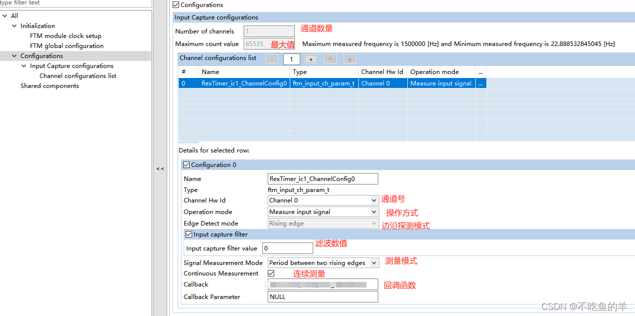
生成代码如下,一个配置结构体下面有一个通道结构体。
/* Channels configuration structure for flexTimer_ic1 input capture */
 ftm_input_ch_param_t flexTimer_ic1_InputCaptureChannelConfig[1] =
{
    {
     0U, /* Channel id */
     FTM_SIGNAL_MEASUREMENT, /* Input capture operation mode */
     FTM_RISING_EDGE, /* Edge alignment mode */
     FTM_RISING_EDGE_PERIOD_MEASUREMENT, /* Signal measurement operation type */
     0U, /* Filter value */
     false, /* Filter state (enabled/disabled) */
     true, /* Continuous measurement state */
     NULL, /* Vector of callbacks  parameters for channels events */
     FanTachInputCapture_IRQHandler /* Vector of callbacks for channels events */
    }
};

/* Input capture configuration for flexTimer_ic1 */
 ftm_input_param_t flexTimer_ic1_InputCaptureConfig =
{
     1U, /* Number of channels */
     65535U, /* Max count value */
     flexTimer_ic1_InputCaptureChannelConfig /* Channels configuration */
};
接口使用
接口在SDK\platform\drivers\src\ftm\ftm_common.c里面
FTM_DRV_Init
根据FTM设备配置结构体初始化,配置状态由state获取。
/*FUNCTION**********************************************************************
 *
 * Function Name : FTM_DRV_Init
 * Description   : Initializes the FTM driver and get the clock frequency value
 * which select one of three possible clock sources for the FTM counter.
 *
 * Implements    : FTM_DRV_Init_Activity
 *END**************************************************************************/
status_t FTM_DRV_Init(uint32_t instance,
                      const ftm_user_config_t * info,
                      ftm_state_t * state)
{
    DEV_ASSERT(instance < FTM_INSTANCE_COUNT);
    DEV_ASSERT(info != NULL);
    DEV_ASSERT(state != NULL);
    DEV_ASSERT((info->ftmClockSource == FTM_CLOCK_SOURCE_SYSTEMCLK) || \
               (info->ftmClockSource == FTM_CLOCK_SOURCE_FIXEDCLK) || \
               (info->ftmClockSource == FTM_CLOCK_SOURCE_EXTERNALCLK));
    FTM_Type * ftmBase = g_ftmBase[instance];
    status_t status = STATUS_SUCCESS;
    uint8_t index = 0U;

    /* Check if this instance is already initialized */
    if (ftmStatePtr[instance] != NULL)
    {
        status = STATUS_ERROR;
    }
    else
    {
        /* Configure state structure. */
        state->ftmClockSource = info->ftmClockSource;
        state->ftmMode = FTM_MODE_NOT_INITIALIZED;
        state->ftmPeriod = 0U;
        ftmStatePtr[instance] = state;

        for (index = 0U; index < FEATURE_FTM_CHANNEL_COUNT; index++)
        {
            state->measurementResults[index] = 0U;
            state->channelsCallbacksParams[index] = NULL;
            state->channelsCallbacks[index] = NULL;
            state->enableNotification[index] = false;
        }

        /* The reset operation doesn't care about write protection. FTM_DRV_Reset will
         * disable this protection.*/
        FTM_DRV_Reset(ftmBase);
        FTM_DRV_InitModule(ftmBase, info->ftmPrescaler);
        /* Get clock name used to configure the FlexTimer module */
        state->ftmSourceClockFrequency = FTM_DRV_GetFrequency(instance);
        /* Check the functional clock is selected for FTM */
        DEV_ASSERT(state->ftmSourceClockFrequency > 0U);
    }

    if (STATUS_SUCCESS == status)
    {
        /* Check if the mode operation in PWM mode */
        if ((FTM_MODE_EDGE_ALIGNED_PWM == info->ftmMode) || (FTM_MODE_CEN_ALIGNED_PWM == info->ftmMode) || (FTM_MODE_OUTPUT_COMPARE == info->ftmMode))
        {
            /* Configure sync for between registers and buffers */
            status = FTM_DRV_SetSync(instance, &(info->syncMethod));
        }

        /* Enable the generation of initialization trigger on chip module */
        FTM_DRV_SetInitTriggerCmd(ftmBase, info->enableInitializationTrigger);
        FTM_DRV_SetBdmMode(ftmBase, info->BDMMode);

        /* Check if enable interrupt in counter mode */
        if (info->isTofIsrEnabled)
        {
            FTM_DRV_SetTimerOverflowInt(ftmBase, true);
            INT_SYS_EnableIRQ(g_ftmOverflowIrqId[instance]);
        }
        else
        {
            FTM_DRV_SetTimerOverflowInt(ftmBase, false);
            INT_SYS_DisableIRQ(g_ftmOverflowIrqId[instance]);
        }
    }

    return status;
}
FTM_DRV_Deinit
逆初始化,整个设备都逆初始化,包括里面所有通道。
/*FUNCTION**********************************************************************
 *
 * Function Name : FTM_DRV_Deinit
 * Description   : Shuts down the FTM driver.
 * First, FTM_DRV_Init must be called. Then this function will disables the FTM module.
 *
 * Implements    : FTM_DRV_Deinit_Activity
 *END**************************************************************************/
status_t FTM_DRV_Deinit(uint32_t instance)
{
    DEV_ASSERT(instance < FTM_INSTANCE_COUNT);
    FTM_Type * ftmBase = g_ftmBase[instance];

    /* Reset all FTM register */
    FTM_DRV_Reset(ftmBase);
    ftmStatePtr[instance] = NULL;

    return STATUS_SUCCESS;
}
FTM_DRV_GetDefaultConfig
获取默认配置结构体,就是你不会配置的时候又它来给你自动配也可以。
/*FUNCTION**********************************************************************
 *
 * Function Name : FTM_DRV_GetDefaultConfig
 * Description   : This function will get the default configuration values
 * in the structure which is used as a common use-case.
 * Return        : None
 * Implements    : FTM_DRV_GetDefaultConfig_Activity
 *END**************************************************************************/
void FTM_DRV_GetDefaultConfig(ftm_user_config_t * const config)
{
    DEV_ASSERT(config != NULL);

    config->syncMethod.softwareSync     = true;
    config->syncMethod.hardwareSync0    = false;
    config->syncMethod.hardwareSync1    = false;
    config->syncMethod.hardwareSync2    = false;
    config->syncMethod.maxLoadingPoint  = false;
    config->syncMethod.minLoadingPoint  = false;
    config->syncMethod.inverterSync     = FTM_SYSTEM_CLOCK;
    config->syncMethod.outRegSync       = FTM_SYSTEM_CLOCK;
    config->syncMethod.maskRegSync      = FTM_SYSTEM_CLOCK;
    config->syncMethod.initCounterSync  = FTM_SYSTEM_CLOCK;
    config->syncMethod.autoClearTrigger = true;
    config->syncMethod.syncPoint        = FTM_UPDATE_NOW;

    config->ftmMode                     = FTM_MODE_EDGE_ALIGNED_PWM;
    config->ftmPrescaler                = FTM_CLOCK_DIVID_BY_1;
    config->ftmClockSource              = FTM_CLOCK_SOURCE_SYSTEMCLK;
    config->BDMMode                     = FTM_BDM_MODE_11;
    config->isTofIsrEnabled             = false;
    config->enableInitializationTrigger = false;
}
FTM_DRV_MaskOutputChannels
屏蔽指定通道
/*FUNCTION**********************************************************************
 *
 * Function Name : FTM_DRV_MaskOutputChannels
 * Description   : This function will mask the output of the channels and at match
 * events will be ignored by the masked channels.
 *
 * Implements : FTM_DRV_MaskOutputChannels_Activity
 *END**************************************************************************/
status_t FTM_DRV_MaskOutputChannels(uint32_t instance,
                                    uint32_t channelsMask,
                                    bool softwareTrigger)
{
    DEV_ASSERT(instance < FTM_INSTANCE_COUNT);
    FTM_Type * ftmBase = g_ftmBase[instance];

    FTM_DRV_SetOutmaskReg(ftmBase, channelsMask);
    FTM_DRV_SetSoftwareTriggerCmd(ftmBase, softwareTrigger);

    return STATUS_SUCCESS;
}
FTM_DRV_SetInitialCounterValue
配置计数器初始值
/*FUNCTION**********************************************************************
 *
 * Function Name : FTM_DRV_SetInitialCounterValue
 * Description   : This function configure the initial counter value. The counter
 * will get this value after an overflow event.
 *
 * Implements : FTM_DRV_SetInitialCounterValue_Activity
 *END**************************************************************************/
status_t FTM_DRV_SetInitialCounterValue(uint32_t instance,
                                        uint16_t counterValue,
                                        bool softwareTrigger)
{
    DEV_ASSERT(instance < FTM_INSTANCE_COUNT);
    FTM_Type * ftmBase = g_ftmBase[instance];

    FTM_DRV_SetCounterInitVal(ftmBase, counterValue);
    FTM_DRV_SetSoftwareTriggerCmd(ftmBase, softwareTrigger);

    return STATUS_SUCCESS;
}
FTM_DRV_SetHalfCycleReloadPoint
配置重载值
/*FUNCTION**********************************************************************
 *
 * Function Name : FTM_DRV_SetHalfCycleReloadPoint
 * Description   : This function configure the value of the counter which will
 * generates an reload point.
 *
 * Implements : FTM_DRV_SetHalfCycleReloadPoint_Activity
 *END**************************************************************************/
status_t FTM_DRV_SetHalfCycleReloadPoint(uint32_t instance,
                                         uint16_t reloadPoint,
                                         bool softwareTrigger)
{
    DEV_ASSERT(instance < FTM_INSTANCE_COUNT);
    FTM_Type * ftmBase = g_ftmBase[instance];

    FTM_DRV_SetHalfCycleValue(ftmBase, reloadPoint);
    FTM_DRV_SetSoftwareTriggerCmd(ftmBase, softwareTrigger);

    return STATUS_SUCCESS;
}
FTM_DRV_SetSoftOutChnValue
将强制通道的输出值为特定值
/*FUNCTION**********************************************************************
 *
 * Function Name : FTM_DRV_SetSoftOutChnValue
 * Description   : This function will force the output value of a channel to a specific value.
 * Before using this function it's mandatory to mask the match events using
 * FTM_DRV_MaskOutputChannels and to enable software output control using
 * FTM_DRV_SetSoftwareOutputChannelControl.
 *
 * Implements : FTM_DRV_SetSoftOutChnValue_Activity
 *END**************************************************************************/
status_t FTM_DRV_SetSoftOutChnValue(uint32_t instance,
                                    uint8_t channelsValues,
                                    bool softwareTrigger)
{
    DEV_ASSERT(instance < FTM_INSTANCE_COUNT);
    FTM_Type * ftmBase = g_ftmBase[instance];
    FTM_DRV_SetAllChnSoftwareCtrlVal(ftmBase, channelsValues ^ (uint8_t)ftmBase->POL);
    FTM_DRV_SetSoftwareTriggerCmd(ftmBase, softwareTrigger);

    return STATUS_SUCCESS;
}
FTM_DRV_SetSoftwareOutputChannelControl
配置哪个输出通道可以由软件控制
/*FUNCTION**********************************************************************
 *
 * Function Name : FTM_DRV_SetSoftwareOutputChannelControl
 * Description   : This function will configure which output channel can be
 * software controlled.
 *
 * Implements : FTM_DRV_SetSoftwareOutputChannelControl_Activity
 *END**************************************************************************/
status_t FTM_DRV_SetSoftwareOutputChannelControl(uint32_t instance,
                                                 uint8_t channelsMask,
                                                 bool softwareTrigger)
{
    DEV_ASSERT(instance < FTM_INSTANCE_COUNT);
    FTM_Type * ftmBase = g_ftmBase[instance];
    FTM_DRV_SetAllChnSoftwareCtrlCmd(ftmBase, channelsMask);
    FTM_DRV_SetSoftwareTriggerCmd(ftmBase, softwareTrigger);

    return STATUS_SUCCESS;
}
FTM_DRV_SetAllChnSoftwareOutputControl
控制通道列表输出到指定的值
/*FUNCTION**********************************************************************
 *
 * Function Name : FTM_DRV_SetAllChnSoftwareOutputControl
 * Description   : This function will control list of channels by software to force
 * the output to specified value.
 * Despite the odd channels are configured as HIGH/LOW, they will be inverted in the following
 * configuration: COMP bit = 1 and CH(n)OCV and CH(n+1)OCV are HIGH. Please check Software
 * output control behavior chapter from RM.
 *
 * Implements : FTM_DRV_SetAllChnSoftwareOutputControl_Activity
 *END**************************************************************************/
status_t FTM_DRV_SetAllChnSoftwareOutputControl(uint32_t instance,
                                                uint8_t channelMask,
                                                uint8_t channelValueMask,
                                                bool softwareTrigger)
{
    DEV_ASSERT(instance < FTM_INSTANCE_COUNT);
    FTM_Type * ftmBase = g_ftmBase[instance];
    uint16_t value = 0U;

    value = (uint16_t)(((uint16_t)channelValueMask ^ (uint16_t)ftmBase->POL) << (uint16_t)8U) | (uint16_t)channelMask;

    /* Enable and force the software control of channels output */
    FTM_DRV_SoftwareOutputControl(ftmBase, value);
    FTM_DRV_SetSoftwareTriggerCmd(ftmBase, softwareTrigger);

    return STATUS_SUCCESS;
}
FTM_DRV_SetInvertingControl
基本不会用
/*FUNCTION**********************************************************************
 *
 * Function Name : FTM_DRV_SetInvertingControl
 * Description   : This function will configure if the second channel of a pair
 * will be inverted or not.
 *
 * Implements : FTM_DRV_SetInvertingControl_Activity
 *END**************************************************************************/
status_t FTM_DRV_SetInvertingControl(uint32_t instance,
                                     uint8_t channelsPairMask,
                                     bool softwareTrigger)
{
    DEV_ASSERT(instance < FTM_INSTANCE_COUNT);
    FTM_Type * ftmBase = g_ftmBase[instance];

    FTM_DRV_SetInvctrlReg(ftmBase, channelsPairMask);
    FTM_DRV_SetSoftwareTriggerCmd(ftmBase, softwareTrigger);

    return STATUS_SUCCESS;
}
FTM_DRV_SetModuloCounterValue
配置最大计数值
/*FUNCTION**********************************************************************
 *
 * Function Name : FTM_DRV_SetModuloCounterValue
 * Description   : This function configure the maximum counter value.
 *
 * Implements : FTM_DRV_SetModuloCounterValue_Activity
 *END**************************************************************************/
status_t FTM_DRV_SetModuloCounterValue(uint32_t instance,
                                       uint16_t counterValue,
                                       bool softwareTrigger)
{
    DEV_ASSERT(instance < FTM_INSTANCE_COUNT);
    FTM_Type * ftmBase = g_ftmBase[instance];

    FTM_DRV_SetMod(ftmBase, counterValue);
    FTM_DRV_SetSoftwareTriggerCmd(ftmBase, softwareTrigger);

    return STATUS_SUCCESS;
}
FTM_DRV_SetOutputlevel
设置通道电平
/*FUNCTION**********************************************************************
 *
 * Function Name : FTM_DRV_SetOutputlevel
 * Description   : This function will set the channel edge or level on the selection
 * of the channel mode.
 *
 * Implements : FTM_DRV_SetOutputlevel_Activity
 *END**************************************************************************/
status_t FTM_DRV_SetOutputlevel(uint32_t instance,
                                uint8_t channel,
                                uint8_t level)
{
    DEV_ASSERT(instance < FTM_INSTANCE_COUNT);
    DEV_ASSERT(channel < FEATURE_FTM_CHANNEL_COUNT);
    FTM_Type * ftmBase = g_ftmBase[instance];

    /* Sets the channel edge or level selection */
    FTM_DRV_SetChnEdgeLevel(ftmBase, channel, level);

    return STATUS_SUCCESS;
}
FTM_DRV_SetSync
设置为同步
/*FUNCTION**********************************************************************
 *
 * Function Name : FTM_DRV_SetSync
 * Description   : This function configure the synchronization for PWM register
 * (CnV, MOD, CINT, HCR, OUTMASK).If this function is used whit wrong parameters
 * it's possible to generate wrong waveform. Registers synchronization need to
 * be configured for PWM and output compare mode.
 *
 * Implements : FTM_DRV_SetSync_Activity
 *END**************************************************************************/
status_t FTM_DRV_SetSync(uint32_t instance,
                         const ftm_pwm_sync_t * param)
{
    DEV_ASSERT(instance < FTM_INSTANCE_COUNT);
    DEV_ASSERT(param != NULL);
    FTM_Type * ftmBase = g_ftmBase[instance];
    status_t retStatus = STATUS_SUCCESS;
    bool hardwareSync = param->hardwareSync0 || param->hardwareSync1 || param->hardwareSync2;

    /* Software and hardware triggers are not allowed in the same time */
    if ((param->softwareSync && hardwareSync) || (true != (param->softwareSync || hardwareSync)))
    {
        retStatus = STATUS_ERROR;
    }
    else if (param->softwareSync)
    {
        /* Configure sync for OUTMASK register */
        FTM_DRV_SetOutmaskSoftwareSyncModeCmd(ftmBase, true);
        /* Configure sync for INVCTRL register */
        FTM_DRV_SetInvctrlSoftwareSyncModeCmd(ftmBase, true);
        /* Configure sync for SWOCTRL register */
        FTM_DRV_SetSwoctrlSoftwareSyncModeCmd(ftmBase, true);
        /* Configure sync for MOD, HCR, CNTIN, and CnV registers */
        FTM_DRV_SetModCntinCvSoftwareSyncModeCmd(ftmBase, true);
        /* Configure synchronization method (waiting next loading point or now) */
        FTM_DRV_SetCounterSoftwareSyncModeCmd(ftmBase, param->syncPoint);
    }
    else
    {
        /* Configure sync for OUTMASK register */
        FTM_DRV_SetOutmaskHardwareSyncModeCmd(ftmBase, true);
        /* Configure sync for INVCTRL register */
        FTM_DRV_SetInvctrlHardwareSyncModeCmd(ftmBase, true);
        /* Configure sync for SWOCTRL register */
        FTM_DRV_SetSwoctrlHardwareSyncModeCmd(ftmBase, true);
        /* Configure sync for MOD, HCR, CNTIN, and CnV registers */
        FTM_DRV_SetModCntinCvHardwareSyncModeCmd(ftmBase, true);
        /* Configure synchronization method (waiting next loading point or now) */
        FTM_DRV_SetCounterHardwareSyncModeCmd(ftmBase, (bool)param->syncPoint);
    }

    if (STATUS_SUCCESS == retStatus)
    {
        /* Enhanced PWM sync is used */
        FTM_DRV_SetPwmSyncModeCmd(ftmBase, true);
        /* Configure trigger source for sync */
        FTM_DRV_SetHardwareSyncTriggerSrc(ftmBase, 0U, param->hardwareSync0);
        FTM_DRV_SetHardwareSyncTriggerSrc(ftmBase, 1U, param->hardwareSync1);
        FTM_DRV_SetHardwareSyncTriggerSrc(ftmBase, 2U, param->hardwareSync2);
        /* Configure loading points */
        FTM_DRV_SetMaxLoadingCmd(ftmBase, param->maxLoadingPoint);
        FTM_DRV_SetMinLoadingCmd(ftmBase, param->minLoadingPoint);
        /* Configure sync for OUTMASK register */
        FTM_DRV_SetOutmaskPwmSyncModeCmd(ftmBase, (bool)param->maskRegSync);
        /* Configure sync for INVCTRL register */
        FTM_DRV_SetInvctrlPwmSyncModeCmd(ftmBase, param->inverterSync);
        /* Configure sync for SWOCTRL register */
        FTM_DRV_SetSwoctrlPwmSyncModeCmd(ftmBase, param->outRegSync);
        /* Configure sync for MOD, HCR, CNTIN, and CnV registers */
        FTM_DRV_SetCntinPwmSyncModeCmd(ftmBase, param->initCounterSync);
        /* Configure if FTM clears TRIGj (j=0,1,2) when the hardware trigger j is detected. */
        FTM_DRV_SetHwTriggerSyncModeCmd(ftmBase, param->autoClearTrigger);
    }

    return retStatus;
}
FTM_DRV_GenerateHardwareTrigger
配置硬件触发源
/*FUNCTION**********************************************************************
 *
 * Function Name : FTM_DRV_GenerateHardwareTrigger
 * Description   : This function is used to configure a trigger source for FTM instance.
 * This allow a hardware trigger input which can be used in PWM synchronization.
 * Note that the hardware trigger is implemented only on trigger 1 for each instance.
 *
 * Implements : FTM_DRV_GenerateHardwareTrigger_Activity
 *END**************************************************************************/
status_t FTM_DRV_GenerateHardwareTrigger(uint32_t instance)
{
    DEV_ASSERT(instance < FTM_INSTANCE_COUNT);
    SIM_Type * simeBase = SIM_BASE_PTRS;

    FTM_DRV_SyncBit(simeBase, instance, true);

    return STATUS_SUCCESS;
}
FTM_DRV_EnableInterrupts
使能中断
/*FUNCTION**********************************************************************
 *
 * Function Name : FTM_DRV_EnableInterrupts
 * Description   : This function will enable the generation a list of interrupts.
 * It includes the FTM overflow interrupts, the reload point interrupt, the fault
 * interrupt and the channel (n) interrupt.
 *
 * Implements : FTM_DRV_EnableInterrupts_Activity
 *END**************************************************************************/
status_t FTM_DRV_EnableInterrupts(uint32_t instance,
                                  uint32_t interruptMask)
{
    DEV_ASSERT(instance < FTM_INSTANCE_COUNT);
    FTM_Type * ftmBase = g_ftmBase[instance];
    uint32_t chnlInts = (interruptMask & 0x000000FFU);
    uint8_t channel = 0U;

    /* Enable the timer overflow interrupt */
    if ((interruptMask & (uint32_t)FTM_TIME_OVER_FLOW_INT_ENABLE) != 0x0U)
    {
        FTM_DRV_SetTimerOverflowInt(ftmBase, true);
        INT_SYS_EnableIRQ(g_ftmOverflowIrqId[instance]);
    }

    /* Enable the fault interrupt */
    if ((interruptMask & (uint32_t)FTM_FAULT_INT_ENABLE) != 0x0U)
    {
        FTM_DRV_SetFaultInt(ftmBase, true);
        INT_SYS_EnableIRQ(g_ftmFaultIrqId[instance]);
    }

    /* Enable the reload interrupt */
    if ((interruptMask & (uint32_t)FTM_RELOAD_INT_ENABLE) != 0x0U)
    {
        FTM_DRV_SetReIntEnabledCmd(ftmBase, true);
        INT_SYS_EnableIRQ(g_ftmReloadIrqId[instance]);
    }

    /* Enable the channel interrupts */
    while (chnlInts != 0U)
    {
        if ((chnlInts & 0x1U) != 0x0U)
        {
            FTM_DRV_EnableChnInt(ftmBase, channel);
            INT_SYS_EnableIRQ(g_ftmIrqId[instance][channel]);
        }
        channel++;
        chnlInts = chnlInts >> 1U;
    }

    return STATUS_SUCCESS;
}
FTM_DRV_DisableInterrupts
失能中断
/*FUNCTION**********************************************************************
 *
 * Function Name : FTM_DRV_DisableInterrupts
 * Description   : This function is used to disable some interrupts.
 *
 * Implements : FTM_DRV_DisableInterrupts_Activity
 *END**************************************************************************/
void FTM_DRV_DisableInterrupts(uint32_t instance,
                               uint32_t interruptMask)
{
    DEV_ASSERT(instance < FTM_INSTANCE_COUNT);
    FTM_Type * ftmBase = g_ftmBase[instance];
    uint32_t chnlInts = (interruptMask & 0x000000FFU);
    uint8_t channel = 0U;

    /* Disable the timer overflow interrupt */
    if ((interruptMask & (uint32_t)FTM_TIME_OVER_FLOW_INT_ENABLE) != 0x0U)
    {
        FTM_DRV_SetTimerOverflowInt(ftmBase, false);
        INT_SYS_DisableIRQ(g_ftmOverflowIrqId[instance]);
    }

    /* Disable the fault interrupt */
    if ((interruptMask & (uint32_t)FTM_FAULT_INT_ENABLE) != 0x0U)
    {
        FTM_DRV_SetFaultInt(ftmBase, false);
        INT_SYS_DisableIRQ(g_ftmFaultIrqId[instance]);
    }

    /* Disable the reload interrupt */
    if ((interruptMask & (uint32_t)FTM_RELOAD_INT_ENABLE) != 0x0U)
    {
        FTM_DRV_SetReIntEnabledCmd(ftmBase, false);
        INT_SYS_DisableIRQ(g_ftmReloadIrqId[instance]);
    }

    /* Disable the channel interrupts */
    while (chnlInts != 0U)
    {
        if ((chnlInts & 0x1U) != 0x0U)
        {
            FTM_DRV_DisableChnInt(ftmBase, channel);
            INT_SYS_DisableIRQ(g_ftmIrqId[instance][channel]);
        }
        channel++;
        chnlInts = chnlInts >> 1U;
    }
}
FTM_DRV_GetEnabledInterrupts
看看中断是不是使能了
/*FUNCTION**********************************************************************
 *
 * Function Name : FTM_DRV_GetEnabledInterrupts
 * Description   : This function will get the enabled FTM interrupts.
 *
 * Implements : FTM_DRV_GetEnabledInterrupts_Activity
 *END**************************************************************************/
uint32_t FTM_DRV_GetEnabledInterrupts(uint32_t instance)
{
    DEV_ASSERT(instance < FTM_INSTANCE_COUNT);
    FTM_Type const * ftmBase = g_ftmBase[instance];
    uint32_t enabledInterrupts = 0U;
    uint8_t channel = FEATURE_FTM_CHANNEL_COUNT;


    /* Check if timer overflow interrupt is enabled */
    if (FTM_DRV_IsOverflowIntEnabled(ftmBase) == true)
    {
        enabledInterrupts |= (uint32_t)FTM_TIME_OVER_FLOW_INT_ENABLE;
    }

    /* Check if fault interrupt is enabled */
    if (FTM_DRV_IsFaultIntEnabled(ftmBase) == true)
    {
        enabledInterrupts |= (uint32_t)FTM_FAULT_INT_ENABLE;
    }

    /* Check if the reload interrupt is enabled */
    if (FTM_DRV_IsReloadIntEnabled(ftmBase) == true)
    {
        enabledInterrupts |= (uint32_t)FTM_RELOAD_INT_ENABLE;
    }

    /* Check if the channel interrupts are enabled */
    while (channel > 0U)
    {
        channel--;
        if (FTM_DRV_IsChnIntEnabled(ftmBase, channel) == true)
        {
            enabledInterrupts |= (1UL << (uint32_t)channel);
        }
    }

    return enabledInterrupts;
}
FTM_DRV_GetStatusFlags
获取状态标志位
/*FUNCTION**********************************************************************
 *
 * Function Name : FTM_DRV_GetStatusFlags
 * Description   : This function will get the FTM status flags.
 *
 * Implements : FTM_DRV_GetStatusFlags_Activity
 *END**************************************************************************/
uint32_t FTM_DRV_GetStatusFlags(uint32_t instance)
{
    DEV_ASSERT(instance < FTM_INSTANCE_COUNT);
    FTM_Type const * ftmBase = g_ftmBase[instance];
    uint8_t channel = 0U;
    uint32_t statusFlags = 0U;

    /* Check the timer flag */
    if (FTM_DRV_HasTimerOverflowed(ftmBase) == true)
    {
        statusFlags |= (uint32_t)FTM_TIME_OVER_FLOW_FLAG;
    }

    /* Check fault flag */
    if (FTM_DRV_GetDetectedFaultInput(ftmBase) == true)
    {
        statusFlags |= (uint32_t)FTM_FAULT_FLAG;
    }

    /* Check reload flag */
    if (FTM_DRV_GetReloadFlag(ftmBase) == true)
    {
        statusFlags |= (uint32_t)FTM_RELOAD_FLAG;
    }

    /* Check channel trigger flag */
    if (FTM_DRV_IsChnTriggerGenerated(ftmBase) == true)
    {
        statusFlags |= (uint32_t)FTM_CHANNEL_TRIGGER_FLAG;
    }

    /* Lower 8 bits contain the channel status flags */
    for (channel = 0U; channel < FEATURE_FTM_CHANNEL_COUNT; channel++)
    {
        if (FTM_DRV_HasChnEventOccurred(ftmBase, channel) == true)
        {
            statusFlags |= (1UL << (uint32_t)channel);
        }
    }

    return statusFlags;
}
FTM_DRV_ClearStatusFlags
清除状态标志位
/*FUNCTION**********************************************************************
 *
 * Function Name : FTM_DRV_ClearStatusFlags
 * Description   : This function is used to clear the FTM status flags.
 *
 * Implements : FTM_DRV_ClearStatusFlags_Activity
 *END**************************************************************************/
void FTM_DRV_ClearStatusFlags(uint32_t instance,
                              uint32_t flagMask)
{
    DEV_ASSERT(instance < FTM_INSTANCE_COUNT);
    FTM_Type * ftmBase = g_ftmBase[instance];
    uint32_t chnlMask = (flagMask & 0x000000FFU);
    uint8_t channel = 0U;

    /* Clear the timer overflow flag by writing a 0 to the bit while it is set */
    if ((flagMask & (uint32_t)FTM_TIME_OVER_FLOW_FLAG) != 0x0U)
    {
        FTM_DRV_ClearTimerOverflow(ftmBase);
    }

    /* Clear fault flag by writing a 0 to the bit while it is set */
    if ((flagMask & (uint32_t)FTM_FAULT_FLAG) != 0x0U)
    {
        FTM_DRV_ClearFaultsIsr(ftmBase);
    }

    /* Check reload flag by writing a 0 to the bit while it is set */
    if ((flagMask & (uint32_t)FTM_RELOAD_FLAG) != 0x0U)
    {
        FTM_DRV_ClearReloadFlag(ftmBase);
    }

    /* Clear channel trigger flag */
    if ((flagMask & (uint32_t)FTM_CHANNEL_TRIGGER_FLAG) != 0x0U)
    {
        FTM_DRV_ClearChnTriggerFlag(ftmBase);
    }

    /* Clear the channel status flags by writing a 0 to the bit */
    for (channel = 0U; channel < FEATURE_FTM_CHANNEL_COUNT; channel++)
    {
        if ((chnlMask & 0x00000001U) != 0x0U)
        {
            FTM_DRV_ClearChnEventStatus(ftmBase, channel);
        }
        chnlMask = chnlMask >> 1U;
    }
}
FTM_DRV_GetFrequency
获取频率,这个在初始化函数里面用到,这个其实是可以让用户直接调用的。
/*FUNCTION**********************************************************************
 *
 * Function Name : FTM_DRV_GetFrequency
 * Description   : Retrieves the frequency of the clock source feeding the FTM counter.
 * Function will return a 0 if no clock source is selected and the FTM counter is disabled.
 * The returned value is clock sources for the FTM counter.
 *
 * Implements    : FTM_DRV_GetFrequency_Activity
 *END**************************************************************************/
uint32_t FTM_DRV_GetFrequency(uint32_t instance)
{
    DEV_ASSERT(instance < FTM_INSTANCE_COUNT);
    FTM_Type const * ftmBase = g_ftmBase[instance];
    status_t returnCode = STATUS_SUCCESS;
    clock_names_t ftmClkName;
    uint8_t clkPs;
    uint32_t frequency = 0U;
    const ftm_state_t * state = ftmStatePtr[instance];
    clkPs = (uint8_t)(1U << FTM_DRV_GetClockPs(ftmBase));

    switch (state->ftmClockSource)
    {
        case FTM_CLOCK_SOURCE_EXTERNALCLK:
            returnCode = CLOCK_SYS_GetFreq(g_ftmExtClockSel[instance][1], &frequency);
            if (0U == frequency)
            {
                ftmClkName = g_ftmExtClockSel[instance][0];
            }
            else
            {
                ftmClkName = g_ftmExtClockSel[instance][1];
            }

            /* Get the clock frequency value */
            returnCode = CLOCK_SYS_GetFreq(ftmClkName, &frequency);
            break;
        case FTM_CLOCK_SOURCE_FIXEDCLK:
            /* Get the clock frequency value */
            returnCode = CLOCK_SYS_GetFreq(SIM_RTCCLK_CLK, &frequency);
            break;
        case FTM_CLOCK_SOURCE_SYSTEMCLK:
            /* Get the clock frequency value */
            returnCode = CLOCK_SYS_GetFreq(CORE_CLK, &frequency);
            break;
        default:
            /* Nothing to do */
            break;
    }

    /* Checks the functional clock of FTM module */
    (void)returnCode;
    DEV_ASSERT(returnCode == STATUS_SUCCESS);

    return (uint32_t)(frequency / clkPs);
}
FTM_DRV_ConvertFreqToPeriodTicks
将频率转换为周期,也是初始化函数里面用到
/*FUNCTION**********************************************************************
 *
 * Function Name : FTM_DRV_ConvertFreqToPeriodTicks
 * Description   : This function converts the input parameters representing
 * frequency in Hz to a period value in ticks needed by the hardware timer.
 *
 * Implements    : FTM_DRV_ConvertFreqToPeriodTicks_Activity
 *END**************************************************************************/
uint16_t FTM_DRV_ConvertFreqToPeriodTicks(uint32_t instance,
                                          uint32_t freqencyHz)
{
    DEV_ASSERT(instance < FTM_INSTANCE_COUNT);
    DEV_ASSERT(freqencyHz != 0U);
    uint32_t uFTMhz;
    const ftm_state_t * state = ftmStatePtr[instance];
    uFTMhz = state->ftmSourceClockFrequency;

    return (uint16_t)(uFTMhz / freqencyHz);
}
FTM_DRV_CounterReset
计数器清零
/*FUNCTION**********************************************************************
 *
 * Function Name : FTM_DRV_CounterReset
 * Description   : This function will allow the FTM to restart the counter to
 * its initial counting value in the register.
 * Note that the configuration is set in the FTM_DRV_SetSync() function to make
 * sure that the FTM registers are updated by software trigger or hardware trigger.
 *
 * Implements : FTM_DRV_CounterReset_Activity
 *END**************************************************************************/
status_t FTM_DRV_CounterReset(uint32_t instance,
                              bool softwareTrigger)
{
    DEV_ASSERT(instance < FTM_INSTANCE_COUNT);
    FTM_Type * ftmBase = g_ftmBase[instance];

    /* Updates the counter with its initial value */
    FTM_DRV_SetCounter(ftmBase, 0U);
    /* Set a software trigger or waiting a hardware trigger */
    FTM_DRV_SetSoftwareTriggerCmd(ftmBase, softwareTrigger);

    return STATUS_SUCCESS;
}
SDK接口
有些接口是SDK里面才有的,也写在这里。
FTM_DRV_InitMeasurement
初始化测量,在初始化通道的时候调用的。
/*FUNCTION**********************************************************************
 *
 * Function Name : FTM_DRV_InitMeasurement
 * Description   : This function is used to initialize the measurement mode in the
 * input capture mode. It is called in the FTM_DRV_InitInputCapture function.
 *
 *END**************************************************************************/
static status_t FTM_DRV_InitMeasurement(uint32_t instance,
                                        uint8_t channel,
                                        bool continuousModeEn,
                                        ftm_signal_measurement_mode_t measurementType)
{
    DEV_ASSERT((channel % 2U) == 0U);
    FTM_Type * ftmBase = g_ftmBase[instance];
    uint8_t chnlPairNum = (uint8_t)(channel >> 1U);
    status_t retStatus = STATUS_SUCCESS;

    /* Enable the dual edge mode */
    FTM_DRV_SetDualEdgeCaptureCmd(ftmBase, chnlPairNum, true);
    /* Enable dual edge input capture */
    FTM_DRV_SetDualChnDecapCmd(ftmBase, chnlPairNum, true);

    /* If continuous mode is set */
    if (true == continuousModeEn)
    {
        /* Set MSnA and MSnB bit */
        FTM_DRV_SetChnMSnBAMode(ftmBase, channel, 3U);
    }
    else
    {
        /* Clear MSnA and Set MSnB bit */
        FTM_DRV_SetChnMSnBAMode(ftmBase, channel, 2U);
    }

    /* Check If want to measure a pulse width or period of the signal */
    if ((FTM_PERIOD_ON_MEASUREMENT == measurementType) || (FTM_RISING_EDGE_PERIOD_MEASUREMENT== measurementType))
    {
        FTM_DRV_SetChnEdgeLevel(ftmBase, channel, 1U);
        if (FTM_PERIOD_ON_MEASUREMENT == measurementType)
        {
            /* Measure time between rising and falling edge - positive duty */
            FTM_DRV_SetChnEdgeLevel(ftmBase, (uint8_t)(channel + 1U), 2U);
        }
        else
        {
            /* If channel (n) is configured to capture falling edges (ELS(n)B:ELS(n)A = 0:1)
             * then channel (n+1) also captures falling edges (ELS(n+1)B:ELS(n+1)A = 0:1) */
            FTM_DRV_SetChnEdgeLevel(ftmBase, (uint8_t)(channel + 1U), 1U);
        }
    }
    else if ((FTM_PERIOD_OFF_MEASUREMENT == measurementType) || (FTM_FALLING_EDGE_PERIOD_MEASUREMENT == measurementType))
    {
        FTM_DRV_SetChnEdgeLevel(ftmBase, channel, 2U);
        if (FTM_PERIOD_OFF_MEASUREMENT == measurementType)
        {
            /* Measure time between falling and rising edge - negative duty */
            FTM_DRV_SetChnEdgeLevel(ftmBase, (uint8_t)(channel + 1U), 1U);
        }
        else
        {
            /* If channel (n) is configured to capture rising edges (ELS(n)B:ELS(n)A = 1:0) than
             * channel (n+1) is setup to capture also raising edges (ELS(n+1)B:ELS(n+1)A = 1:0) */
            FTM_DRV_SetChnEdgeLevel(ftmBase, (uint8_t)(channel + 1U), 2U);
        }
    }
    else
    {
        retStatus = STATUS_ERROR;
    }

    /* Enable the interrupt request for the channel which will indicate that the measurement is done. */
    FTM_DRV_EnableChnInt(ftmBase, (uint8_t)(channel + 1U));
    INT_SYS_EnableIRQ(g_ftmIrqId[instance][channel]);

    return retStatus;
}
FTM_DRV_InitInputCapture
初始化输入通道,也是要在初始化的时候调用。
/*FUNCTION**********************************************************************
 *
 * Function Name : FTM_DRV_InitInputCapture
 * Description   : Configures Channel Input Capture for either getting time-stamps on edge detection
 * or on signal measurement . When the edge specified in the captureMode
 * argument occurs on the channel the FTM counter is captured into the CnV register.
 * The user will have to read the CnV register separately to get this value. The filter
 * function is disabled if the filterVal argument passed in is 0. The filter function
 * is available only on channels 0,1,2,3.
 *
 * Implements    : FTM_DRV_InitInputCapture_Activity
 *END**************************************************************************/
status_t FTM_DRV_InitInputCapture(uint32_t instance,
                                  const ftm_input_param_t * param)
{
    DEV_ASSERT(instance < FTM_INSTANCE_COUNT);
    DEV_ASSERT(param != NULL);
    FTM_Type * ftmBase = g_ftmBase[instance];
    uint8_t chnlPairNum = 0U;
    uint8_t index = 0U;
    uint8_t hwChannel = 0U;
    bool contModeEn;
    ftm_signal_measurement_mode_t measurementType;
    ftm_state_t * state = ftmStatePtr[instance];
    status_t retStatus = STATUS_SUCCESS;

    if ((NULL != state) && (FTM_MODE_NOT_INITIALIZED == state->ftmMode))
    {
        FTM_DRV_SetClockSource(ftmBase, FTM_CLOCK_SOURCE_NONE);
        FTM_DRV_SetCounterInitVal(ftmBase, 0U);
        FTM_DRV_SetMod(ftmBase, param->nMaxCountValue);
        FTM_DRV_SetCpwms(ftmBase, false);
        /* Disable the combine mode */
        FTM_DRV_SetDualChnMofCombineCmd(ftmBase, chnlPairNum, false);
        FTM_DRV_SetDualChnCombineCmd(ftmBase, chnlPairNum, false);

        for (index = 0U; index < param->nNumChannels; index++)
        {
            hwChannel = param->inputChConfig[index].hwChannelId;
            chnlPairNum =  (uint8_t)(hwChannel >> 1U);
            /* Save in state structure user define handlers */
            state->channelsCallbacksParams[hwChannel] =  param->inputChConfig[index].channelsCallbacksParams;
            state->channelsCallbacks[hwChannel] = param->inputChConfig[index].channelsCallbacks;
            state->enableNotification[hwChannel] = true;

            /* Enable filtering for input channels */
            if (hwChannel < CHAN4_IDX)
            {
                if (true == param->inputChConfig[index].filterEn)
                {
                    FTM_DRV_SetChnInputCaptureFilter(ftmBase, hwChannel, (uint8_t)param->inputChConfig[index].filterValue);
                }
                else
                {
                    FTM_DRV_SetChnInputCaptureFilter(ftmBase, hwChannel, 0U);
                }
            }

            if (FTM_EDGE_DETECT == param->inputChConfig[index].inputMode)
            {
                /* Disable the dual edge mode */
                FTM_DRV_SetDualEdgeCaptureCmd(ftmBase, chnlPairNum, false);
                /* Set input capture mode */
                FTM_DRV_SetChnMSnBAMode(ftmBase, hwChannel, 0U);
                /* Set the event which will generate the interrupt */
                FTM_DRV_SetChnEdgeLevel(ftmBase, hwChannel, (uint8_t)param->inputChConfig[index].edgeAlignement);
                /* Enable interrupt request for the current channel */
                FTM_DRV_EnableChnInt(ftmBase, hwChannel);
                INT_SYS_EnableIRQ(g_ftmIrqId[instance][hwChannel]);
            }
            else if (FTM_SIGNAL_MEASUREMENT == param->inputChConfig[index].inputMode)
            {
                measurementType = param->inputChConfig[index].measurementType;
                contModeEn = param->inputChConfig[index].continuousModeEn;
                /* Configure the measurement type */
                retStatus = FTM_DRV_InitMeasurement(instance, hwChannel, contModeEn, measurementType);
            }
            else
            {
                /* Do nothing */
            }

            if (STATUS_SUCCESS != retStatus)
            {
                break;
            }
        }

        if (STATUS_SUCCESS == retStatus)
        {
            state->ftmMode = FTM_MODE_INPUT_CAPTURE;
            /* Set clock source to start the counter */
            FTM_DRV_SetClockSource(ftmBase, state->ftmClockSource);
        }
    }
    else
    {
        retStatus = STATUS_ERROR;
    }

    return retStatus;
}
FTM_DRV_DeinitInputCapture
逆初始化输入捕获
/*FUNCTION**********************************************************************
 *
 * Function Name : FTM_DRV_DeinitInputCapture
 * Description   : Disables Channel Input Capture
 *
 * Implements    : FTM_DRV_DeinitInputCapture_Activity
 *END**************************************************************************/
status_t FTM_DRV_DeinitInputCapture(uint32_t instance,
                                    const ftm_input_param_t * param)
{
    DEV_ASSERT(instance < FTM_INSTANCE_COUNT);
    DEV_ASSERT(param != NULL);
    FTM_Type * ftmBase = g_ftmBase[instance];
    uint8_t chnlPairNum = 0U;
    uint8_t index = 0U;
    uint8_t hwChannel = 0U;
    ftm_state_t * state = ftmStatePtr[instance];
    DEV_ASSERT(state != NULL);

    /* FTM counter is disabled */
    FTM_DRV_SetClockSource(ftmBase, FTM_CLOCK_SOURCE_NONE);
    FTM_DRV_SetCounterInitVal(ftmBase, 0U);
    FTM_DRV_SetMod(ftmBase, 0xFFFFU);
    FTM_DRV_SetCpwms(ftmBase, false);
    for (index = 0U; index < param->nNumChannels; index++)
    {
        hwChannel = param->inputChConfig[index].hwChannelId;
        chnlPairNum =  (uint8_t)(hwChannel >> 1U);
        /* Disable filtering for input channels */
        if (hwChannel < CHAN4_IDX)
        {
            FTM_DRV_SetChnInputCaptureFilter(ftmBase, hwChannel, 0U);
        }

        FTM_DRV_SetDualChnCombineCmd(ftmBase, chnlPairNum, false);
        FTM_DRV_SetDualEdgeCaptureCmd(ftmBase, chnlPairNum, false);
        FTM_DRV_SetChnEdgeLevel(ftmBase, hwChannel, (uint8_t)0U);
        FTM_DRV_DisableChnInt(ftmBase, hwChannel);
    }

    /* Clear Callbacks function from the state structure */
    for (index = 0U; index < FEATURE_FTM_CHANNEL_COUNT; index++)
    {
        state->channelsCallbacksParams[index] =  NULL;
        state->channelsCallbacks[index] = NULL;
    }

    state->ftmMode = FTM_MODE_NOT_INITIALIZED;

    return STATUS_SUCCESS;
}
FTM_DRV_GetInputCaptureMeasurement
获取输入测量的次数,这个函数相当重要,必然用到。
/*FUNCTION**********************************************************************
 *
 * Function Name : FTM_DRV_GetInputCaptureMeasurement
 * Description   : This function is used to calculate the measurement and/or time stamps values
 * which are read from the C(n, n+1)V registers and stored to the static buffers.
 *
 * Implements    : FTM_DRV_GetInputCaptureMeasurement_Activity
 *END**************************************************************************/
uint16_t FTM_DRV_GetInputCaptureMeasurement(uint32_t instance,
                                            uint8_t channel)
{
    DEV_ASSERT(instance < FTM_INSTANCE_COUNT);
    DEV_ASSERT(channel < FEATURE_FTM_CHANNEL_COUNT);
    const ftm_state_t * state = ftmStatePtr[instance];
    uint16_t value = 0U;

    if (state != NULL)
    {
        value = state->measurementResults[channel];
    }

    return value;
}
FTM_DRV_StartNewSignalMeasurement
开始测量
/*FUNCTION**********************************************************************
 *
 * Function Name : FTM_DRV_StartNewSignalMeasurement
 * Description   : This function starts new Signal Measurements on a dual input compare channel
 * that is configured as single-shot measurement.
 *
 * Implements    : FTM_DRV_StartNewSignalMeasurement_Activity
 *END**************************************************************************/
status_t FTM_DRV_StartNewSignalMeasurement(uint32_t instance,
                                           uint8_t channel)
{
    DEV_ASSERT(instance < FTM_INSTANCE_COUNT);
    DEV_ASSERT(channel < FEATURE_FTM_CHANNEL_COUNT);
    /* Clear CH(n)F and CH(n+1)F  flags and Set DECAP bit */
    FTM_Type * ftmBase = g_ftmBase[instance];
    uint8_t chnlPairNum = (uint8_t)(channel >> 1U);
    status_t retStatus = STATUS_SUCCESS;

    /* Get channel mode */
    if (FTM_FEATURE_INPUT_CAPTURE_SINGLE_SHOT == FTM_DRV_GetChnMode(ftmBase, channel))
    {
        if (FTM_DRV_GetDualEdgeCaptureBit(ftmBase, chnlPairNum))
        {
            /* Clear event flags for channel n and n + 1 */
            FTM_DRV_ClearChnEventFlag(ftmBase, (uint8_t)(channel + 1U));
            FTM_DRV_ClearChnEventFlag(ftmBase, channel);
            /* Set DECAP bit to start measurement */
            FTM_DRV_SetDualChnDecapCmd(ftmBase, chnlPairNum, true);
        }
    }
    else
    {
        retStatus = STATUS_ERROR;
    }

    return retStatus;
}
FTM_IC_DRV_SetChannelMode
设置通道模式
/*FUNCTION**********************************************************************
 *
 * Function Name : FTM_IC_DRV_SetChannelMode
 * Description   : This function is used to change the channel mode at run time or
 * when stopping channel. The channel mode is selected in the ftm_ic_op_mode_t
 * enumeration type.
 *
 * Implements    : FTM_IC_DRV_SetChannelMode_Activity
 *END**************************************************************************/
status_t FTM_IC_DRV_SetChannelMode(uint32_t instance,
                                   uint8_t channel,
                                   ftm_ic_op_mode_t inputMode,
                                   bool enableContinuousCapture)
{
    DEV_ASSERT(instance < FTM_INSTANCE_COUNT);
    DEV_ASSERT(channel < FEATURE_FTM_CHANNEL_COUNT);

    FTM_Type * ftmBase = g_ftmBase[instance];
    uint8_t level = 1U;
    uint8_t nextChnlevel = 1U;
    uint8_t channelPair =  (uint8_t)(channel >> 1U);

    if (inputMode == FTM_DISABLE_OPERATION)
    {
        /* Set the edge level to disable operation on the channel input */
        FTM_DRV_SetChnEdgeLevel(ftmBase, channel, 0x0U);
    }
    else if ((inputMode == FTM_TIMESTAMP_RISING_EDGE) ||
             (inputMode == FTM_TIMESTAMP_FALLING_EDGE) ||
             (inputMode == FTM_TIMESTAMP_BOTH_EDGES))
    {
        /* Disable the dual edge mode */
        FTM_DRV_SetDualEdgeCaptureCmd(ftmBase, channelPair, false);
        /* Set input capture mode */
        FTM_DRV_SetChnMSnBAMode(ftmBase, channel, 0U);
        /* Set the event which will generate the interrupt */
        FTM_DRV_SetChnEdgeLevel(ftmBase, channel, (uint8_t)inputMode);
        /* Enable interrupt request for the current channel */
        FTM_DRV_EnableChnInt(ftmBase, channel);
    }
    else
    {
        /* Check the channel is even number */
        DEV_ASSERT((channel % 2U) == 0U);
        /* Enable the dual edge mode */
        FTM_DRV_SetDualEdgeCaptureCmd(ftmBase, channelPair, true);
        /* Enable dual edge input capture */
        FTM_DRV_SetDualChnDecapCmd(ftmBase, channelPair, true);
        /* If continuous mode is set*/
        if (true == enableContinuousCapture)
        {
            /* Set MSnA and MSnB bit*/
            FTM_DRV_SetChnMSnBAMode(ftmBase, channel, 3U);
        }
        else
        {
            /* Clear MSnA and Set MSnB bit*/
            FTM_DRV_SetChnMSnBAMode(ftmBase, channel, 2U);
        }

        /* Check If want to measure a pulse width or period of the signal */
        if ((FTM_MEASURE_PULSE_HIGH == inputMode) || (FTM_MEASURE_RISING_EDGE_PERIOD == inputMode))
        {
            if (FTM_MEASURE_PULSE_HIGH == inputMode)
            {
                /* Measure time between rising and falling edge - positive duty */
                nextChnlevel = 2U;
            }
        }
        else
        {
            level = 2U;
            if (FTM_MEASURE_FALLING_EDGE_PERIOD == inputMode)
            {
                /* If channel (n) is configured to capture rising edges (ELS(n)B:ELS(n)A = 1:0) than
                 * channel (n+1) is setup to capture also raising edges (ELS(n+1)B:ELS(n+1)A = 1:0) */
                nextChnlevel = 2U;
            }
        }

        FTM_DRV_SetChnEdgeLevel(ftmBase, channel, level);
        FTM_DRV_SetChnEdgeLevel(ftmBase, (uint8_t)(channel + 1U), nextChnlevel);

        /* Disable interrupt request for the current channel */
        FTM_DRV_DisableChnInt(ftmBase, channel);
        FTM_DRV_EnableChnInt(ftmBase, (uint8_t)(channel + 1U));
    }

    return STATUS_SUCCESS;
}
初始化操作
由于它有一个设备配置结构体和一个通道配置结构体,所以两个都得初始化,多通道的话,就多初始化几个通道。
FTM_DRV_Init(INST_FLEXTIMER_IC1, &flexTimer_ic1_InitConfig, &ftmStateStruct);
FTM_DRV_InitInputCapture(INST_FLEXTIMER_IC1, &flexTimer_ic1_InputCaptureConfig);
回调函数操作
每次抓到一个周期,都会调用这个FTM的回调函数,这个函数里面通过FTM_DRV_GetInputCaptureMeasurement获取到这个周期的计数次数,现在没1/48M计数器+1,所以看FTM分频多少次,决定了要把结果乘以多少。其实就是把计数次数转换为多少us时间。
uint32_t FTM3_IRQHandler(void)
{
    uint16_t captureCount;
    uint32_t timeSliceUs;
    uint16_t coefficient;

    captureCount = FTM_DRV_GetInputCaptureMeasurement(INST_FLEXTIMER_IC1, 0);
    if (captureCount == 0) {
        return;
    }

    if (flexTimer_ic1_InitConfig.ftmPrescaler == FTM_CLOCK_DIVID_BY_8) {
        coefficient = 1;
    } else if (flexTimer_ic1_InitConfig.ftmPrescaler == FTM_CLOCK_DIVID_BY_16) {
        coefficient = 2;
    } else if (flexTimer_ic1_InitConfig.ftmPrescaler == FTM_CLOCK_DIVID_BY_32) {
        coefficient = 4;
    } else if (flexTimer_ic1_InitConfig.ftmPrescaler == FTM_CLOCK_DIVID_BY_64) {
        coefficient = 8;
    } else if (flexTimer_ic1_InitConfig.ftmPrescaler == FTM_CLOCK_DIVID_BY_128) {
        coefficient = 16;
    }

    timeSliceUs = captureCount * coefficient;

    return timeSliceUs;
}




![[java基础揉碎]Object类详解](https://img-blog.csdnimg.cn/direct/ff94e2d601624394ae09db4a72f111b2.png)
