目录
概述
1 认识I2C协议
1.1 初识I2C
1.2 I2C物理层
1.3 I2C协议分析
1.3.1 Start、Stop、ACK 信号
1.3.2 I2C协议的操作流程
1.3.3 操作I2C注意的问题
2 linux platform驱动开发
2.1 更新设备树
2.1.1 添加驱动节点
2.1.2 编译.dts
2.1.3 更新板卡中的.dtb
2.2 驱动程序设计要点
2.2.1 match设备节点
2.2.2 读写函数的注意点
2.2.2.1 读函数
2.2.2.1 写函数
3 驱动程序实现
3.1 编写驱动程序
3.2 编写Makefile
3.3 编译驱动
4 测试
4.1 编写测试代码
4.2 编写测试程序的Makefile
4.3 编译和运行测试代码
概述
本文主要详细介绍了I2C的知识,使用linux platform驱动架构开发一个基于i2c接口的驱动程序,其中包括编写和更新设备树文件,搭建驱动架构,编写驱动代码和测试代码。本文还是以AT24C02为例,介绍linux platform驱动下i2c类型设备驱动程序的设计方法。并介绍如何使用read和write函数来实现eeprom的读/写功能。
1 认识I2C协议
1.1 初识I2C
I2C 通讯协议(Inter-Integrated Circuit)是由 Philips 公司开发的一种简单、双向二线制同步串行总线, 只需要两根线即可在连接于总线上的器件之间传送信息。I2C 协议占用引脚特别少, 硬件实现简单, 可扩展型强, 现在被广泛地使用在系统内多个集成电路(IC)间的通讯。
1.2 I2C物理层
I2C 通讯设备之间的常用连接方式

物理层结构有如下特点:
1) 一条I2C总线上可以挂载多个设备,不同的设备地址必须不同
2)I2C总线由两条物理线路构成,分别为SCL和SDA,SCL为同步时钟线,SDA为数据线路
3)I2C可支持3中工作模式:标准模式(100k bit/ s),快速模式( 400k bit/ s),高速模式( 3.4M bit/ s)
1.3 I2C协议分析
完整的I2C工作时序图:

1.3.1 Start、Stop、ACK 信号

Start信号:
在空闲状态时,SDA为高电平,SCL也为高电平。当有数据需要传输时,Master首先发起start信号,SDA: 1-->0, SCL: 1
Stop信号:
数据传输完成后,SDA: 0-->1, SCL: 1
ACK信号:
在I2C协议中,数据传输的单位为byte, 传输完成一个数据时,需要8个bit, 在第9个bit( SCL电平: 0-->1)时,SDA : 0。该信号为ACK信号。

1.3.2 I2C协议的操作流程
需要注意的是I2C协议传输数据以字节为单位,每个字节有8个bit,传输完成一个字节后,还会发发送一个响应信号,即ACK信号,所以,其完成一个byte传输,实际需要9个bit。
Step-1: Master 发起Start信号 , SDA: 1---> 0, SCL: 1
Step-2: 传输数据,当SCL: 0 ->1, SDA发送一个bit,总共8个bit
Step-3: ACK信号,SCL: 0->1, SDA 1->0
Step-4: 传送下一个数据(循环执行: step-2 - > step-3)
Step-5: Master 发起Stop信号,SDA: 0--->1, SCL: 1
1.3.3 操作I2C注意的问题
1)空闲状态时,SDA=1, SCL1 =1
2) SCL 电平 0 ->1变化后,高电平保持期间,SDA上的数据才为有效bit
2 linux platform驱动开发
2.1 更新设备树
2.1.1 添加驱动节点
AT24C02引脚和IMX.6ULL引脚对应关系:
| AT24C02 IO | IMX.6ULL PIN |
| SCL | I2C2_SCL |
| SDA | I2C2_SDA |
.dts文件路径:/home/mftang/linux_workspace/study_atk_dl6y2c/kernel/atk-dl6u2c/arch/arm/boot/dts/imx6ull-14x14-evk.dts
在.dts文件中添加如下代码:
    at24c02: at24c02@50 {
        compatible = "atk-dl6y2c,at24c02";
        reg = <0x50>;
    };
其在imx6ull-14x14-evk.dts中位置:

2.1.2 编译.dts
编译.dts文件,并把编译生成的.dtb文件发送到NFS共享目录下,便于在板卡中操作该文件。
1)在内核根目录下使用如下命令编译.dts文件
make dtbs
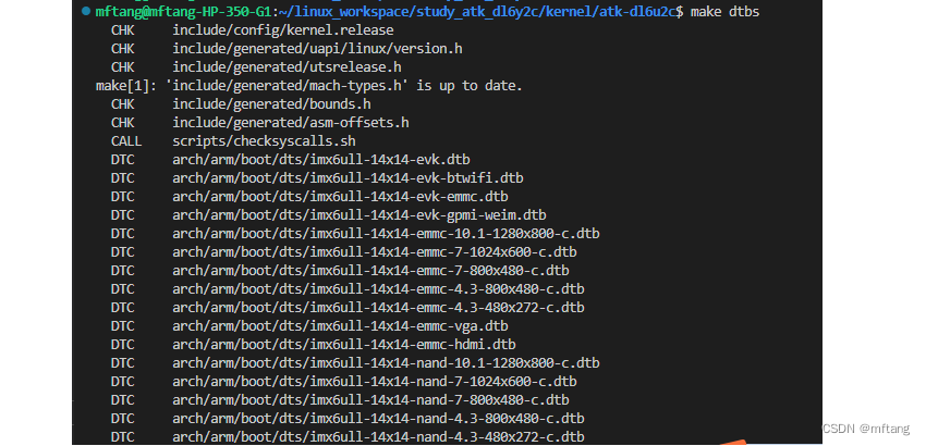
2) 复制 .dtb 文件至NFS共享目录
cp arch/arm/boot/dts/imx6ull-14x14-emmc-4.3-480x272-c.dtb /home/mftang/nfs/atk_dl6y2c/

2.1.3 更新板卡中的.dtb
复制.dtb文件到相应的运行目录,然后重新板卡
cp /mnt/atk_dl6y2c/imx6ull-14x14-emmc-4.3-480x272-c.dtb /run/media/mmcblk1p1

reboot板卡后,内核会重新读取.dtb文件。然后在/proc/device-tree目录下查看板卡device tree,使用如下命令:
cd /sys/bus/i2c/devices
ls

查看地址下设备名称
cat 1-0050/name

2.2 驱动程序设计要点
2.2.1 match设备节点
在板卡的.dts 文件中,定义的设备节点为:

在设备驱动,需要设计相应的匹配表来match该信息,驱动程序的代码如下:
static const struct of_device_id atk_dl6y2c_at24cxx[] = {
    { .compatible = "atk-dl6y2c,at24c02" },
    { },
};

static const struct i2c_device_id at24c02_ids[] = {
    { "xxxxyyy",  (kernel_ulong_t)NULL },
    { /* END OF LIST */ }
};

/*  platform_driver */
static struct i2c_driver at24cxx_driver = {
    .probe      = at24cxx_probe,
    .remove     = at24cxx_remove,
    .driver     = {
        .name   = "atk_at24cxx",
        .of_match_table = atk_dl6y2c_at24cxx,
    },
    .id_table = at24c02_ids,
};
2.2.2 读写函数的注意点
2.2.2.1 读函数
为了实现随机读取EEPROM中的数据,在用户层需要传递一个地址字节,于是该接口设计如下:
int at24cxx_read( unsigned char address, unsigned char *buff, unsigned int len)
{
    int ret;
    unsigned char addrbuff[1];
    struct i2c_msg msg[2];
    struct i2c_client *client = at24cxxdev.client;

    addrbuff[0] = address;
    /* msg[0]为发送要读取的首地址 */
    msg[0].addr = client->addr;            /* at24c02 地址 */
    msg[0].flags = 0;                      /* 标记为发送数据 */
    msg[0].buf = addrbuff;                 /* 读取的首地址 */
    msg[0].len = 1;                         /* reg长度*/

    /* msg[1]读取数据 */
    msg[1].addr = client->addr;             /* at24c02 地址 */
    msg[1].flags = I2C_M_RD;                /* 标记为读取数据*/
    msg[1].buf = buff;                      /* 读取数据缓冲区 */
    msg[1].len = len;                       /* 要读取的数据长度*/

    ret = i2c_transfer(client->adapter, msg, 2);
    mdelay(20);

    if(ret < 0){
        printk("i2c rd failed=%d len=%d\n",ret, len);
    }

    return ret;
}
和设备层相关的read 函数中,使用copy_from_user, 以得到用户层传递进来的参数,具体实现如下:
static ssize_t at24cxx_drv_read(struct file *file, char __user *buf,
                                size_t size, loff_t *offset)
{
    unsigned char tempbuff[size];
    unsigned char kernel_buf[1];
    int err, i;
    unsigned char addr;

    // get address here
    err = copy_from_user(kernel_buf, buf,1);

    addr = kernel_buf[0];
    at24cxx_read( addr, tempbuff, size );
    size = copy_to_user(buf, tempbuff, size);

    return size;
}
2.2.2.1 写函数
要实现随机写AT24C02内存的功能,就需要写数据时,先传递给它一个地址,然后在写数据,所以在驱动程序是这样实现该功能的:
int at24cxx_write(  unsigned char *buff, unsigned int len)
{
    int ret;
    struct i2c_msg msg[1];
    struct i2c_client *client = at24cxxdev.client;

    /* msg[0]为发送要写的首地址 */
    msg[0].addr = client->addr;       /* at24c02 地址 */
    msg[0].flags = 0;                 /* 标记为发送数据 */
    msg[0].buf = buff;                /* 写的首地址 */
    msg[0].len = len;                 /* 数据长度*/

    ret = i2c_transfer(client->adapter, msg, 1);
    mdelay(20);
    if(ret < 0)
    {
        printk("i2c write failed=%d len=%d\n",ret, len);
    }

    return ret;
}
和driver 层相关的write函数如下,其中buff中的数据包含两部分:
buf[0] : 为地址信息,
buf[1 ~ n ] :user层要写的data数据:
static ssize_t at24cxx_drv_write(struct file *file, const char __user *buf, size_t size, loff_t *offset)
{
    unsigned char kernel_buf[size];
    int err, i;

    size = copy_from_user(kernel_buf, buf, size);
    at24cxx_write(kernel_buf, size );

    return size;
}
3 驱动程序实现
3.1 编写驱动程序
创建一个.c 文件,编写代码。详细驱动代码如下:
/***************************************************************
Copyright  2024-2029. All rights reserved.
文件名     : drv_15_at24cxx.c
作者       : tangmingfei2013@126.com
版本       : V1.0
描述       : at24cxx 驱动程序
其他       : 无
日志       : 初版V1.0 2024/1/30

使用方法:
1) 在.dts文件中定义节点信息
    at24c02: at24c02@50 {
        compatible = "atk-dl6y2c,at24c02";
        reg = <0x50>;
    };

2) 在驱动匹配列表
static const struct of_device_id at24cxx_of_match[] = {
    { .compatible = "atk-dl6y2c,at24c02" },
    { } // Sentinel
};
***************************************************************/
#include <linux/types.h>
#include <linux/kernel.h>
#include <linux/delay.h>
#include <linux/ktime.h>
#include <linux/ide.h>
#include <linux/init.h>
#include <linux/module.h>
#include <linux/errno.h>
#include <linux/gpio.h>
#include <linux/cdev.h>
#include <linux/device.h>
#include <linux/of_gpio.h>
#include <linux/semaphore.h>
#include <linux/timer.h>
#include <linux/irq.h>
#include <linux/wait.h>
#include <linux/poll.h>
#include <linux/fs.h>
#include <linux/fcntl.h>
#include <asm/mach/map.h>
#include <asm/uaccess.h>
#include <asm/io.h>
#include <linux/i2c.h>

#define DEVICE_NAME      "at24cxx"     // dev/at24cxx


/* at24cxxdev设备结构体 */
struct at24cxxstru_dev{
    dev_t   devid;                /* 设备号         */
    struct  cdev cdev;            /* cdev           */
    struct  class *class;         /* 类             */
    struct  device *device;       /* 设备           */
    int     major;                /* 主设备号       */
    struct  device_node *node;    /* at24cxx设备节点 */
    struct i2c_client *client;
};

/* read or write at24cxx structure */

static struct at24cxxstru_dev at24cxxdev;

/*
    at24cxx driver
*/
int at24cxx_read( unsigned char address, unsigned char *buff, unsigned int len)
{
    int ret;
    unsigned char addrbuff[1];
    struct i2c_msg msg[2];
    struct i2c_client *client = at24cxxdev.client;

    addrbuff[0] = address;
    /* msg[0]为发送要读取的首地址 */
    msg[0].addr = client->addr;            /* at24c02 地址 */
    msg[0].flags = 0;                      /* 标记为发送数据 */
    msg[0].buf = addrbuff;                 /* 读取的首地址 */
    msg[0].len = 1;                         /* reg长度*/

    /* msg[1]读取数据 */
    msg[1].addr = client->addr;             /* at24c02 地址 */
    msg[1].flags = I2C_M_RD;                /* 标记为读取数据*/
    msg[1].buf = buff;                      /* 读取数据缓冲区 */
    msg[1].len = len;                       /* 要读取的数据长度*/

    ret = i2c_transfer(client->adapter, msg, 2);
    mdelay(20);

    if(ret < 0){
        printk("i2c rd failed=%d len=%d\n",ret, len);
    }

    return ret;
}

int at24cxx_write(  unsigned char *buff, unsigned int len)
{
    int ret;
    struct i2c_msg msg[1];
    struct i2c_client *client = at24cxxdev.client;

    /* msg[0]为发送要写的首地址 */
    msg[0].addr = client->addr;       /* at24c02 地址 */
    msg[0].flags = 0;                 /* 标记为发送数据 */
    msg[0].buf = buff;                /* 写的首地址 */
    msg[0].len = len;                 /* 数据长度*/

    ret = i2c_transfer(client->adapter, msg, 1);
    mdelay(20);
    if(ret < 0)
    {
        printk("i2c write failed=%d len=%d\n",ret, len);
    }

    return ret;
}

/*
    linux driver 驱动接口:
    实现对应的open/read/write等函数,填入file_operations结构体
*/
static ssize_t at24cxx_drv_read(struct file *file, char __user *buf, size_t size, loff_t *offset)
{
    unsigned char tempbuff[size];
    unsigned char kernel_buf[1];
    int err, i;
    unsigned char addr;

    // get address here
    err = copy_from_user(kernel_buf, buf,1);

    addr = kernel_buf[0];
    at24cxx_read( addr, tempbuff, size );
    size = copy_to_user(buf, tempbuff, size);

    return size;
}

static ssize_t at24cxx_drv_write(struct file *file, const char __user *buf, size_t size, loff_t *offset)
{
    unsigned char kernel_buf[size];
    int err, i;

    size = copy_from_user(kernel_buf, buf, size);
    at24cxx_write(kernel_buf, size );

    return size;
}


static int at24cxx_drv_close(struct inode *node, struct file *file)
{
    printk(" %s line %d \r\n",  __FUNCTION__, __LINE__);

    return 0;
}

static int at24cxx_drv_open(struct inode *inode, struct file *filp)
{
    return 0;
}

/*
    定义driver的file_operations结构体
*/
static struct file_operations at24cxx_fops = {
    .owner   = THIS_MODULE,
    .read    = at24cxx_drv_read,
    .write   = at24cxx_drv_write,
    .open    = at24cxx_drv_open,

    .release = at24cxx_drv_close,
};


/* 1. 从platform_device获得GPIO
 * 2. gpio=>irq
 * 3. request_irq
 */
static int at24cxx_probe( struct i2c_client *client, const struct i2c_device_id *id )
{
    printk("at24cxx driver and device was matched!\r\n");

    /* 1. 获得硬件信息 */
    at24cxxdev.client = client;

    /* register file_operations  */
    at24cxxdev.major = register_chrdev( 0,
                                        DEVICE_NAME,     /* device name */
                                        &at24cxx_fops);

    /* create the device class  */
    at24cxxdev.class = class_create(THIS_MODULE, "at24cxx_class");

    if (IS_ERR(at24cxxdev.class)) {
        printk("%s line %d\n", __FUNCTION__, __LINE__);
        unregister_chrdev( at24cxxdev.major, DEVICE_NAME);
        return PTR_ERR( at24cxxdev.class );
    }

    /* 2. device_create */
    device_create( at24cxxdev.class, NULL,
                   MKDEV( at24cxxdev.major, 0 ), NULL,
                   DEVICE_NAME);        // device name

    return 0;
}

static int at24cxx_remove(struct i2c_client *client)
{
    printk("%s line %d\n", __FUNCTION__, __LINE__);

    device_destroy( at24cxxdev.class, MKDEV( at24cxxdev.major, 0));
    class_destroy(at24cxxdev.class);
    unregister_chrdev(at24cxxdev.major, DEVICE_NAME);

    return 0;
}


static const struct of_device_id atk_dl6y2c_at24cxx[] = {
    { .compatible = "atk-dl6y2c,at24c02" },
    { },
};

static const struct i2c_device_id at24c02_ids[] = {
    { "xxxxyyy",  (kernel_ulong_t)NULL },
    { /* END OF LIST */ }
};

/* 1. 定义platform_driver */
static struct i2c_driver at24cxx_driver = {
    .probe      = at24cxx_probe,
    .remove     = at24cxx_remove,
    .driver     = {
        .name   = "atk_at24cxx",
        .of_match_table = atk_dl6y2c_at24cxx,
    },
    .id_table = at24c02_ids,
};

/*
  2. 在入口函数注册platform_driver
*/
static int __init at24cxx_init(void)
{
    int err;

    printk("%s line %d\n",__FUNCTION__, __LINE__);

    err = i2c_add_driver(&at24cxx_driver);

    return err;
}

/* 3. 有入口函数就应该有出口函数:卸载驱动程序时,就会去调用这个出口函数
 *    卸载platform_driver
 */
static void __exit at24cxx_exit(void)
{
    printk("%s line %d\n", __FUNCTION__, __LINE__);

    i2c_del_driver(&at24cxx_driver);
}

/*
 4. 驱动入口和出口函数
*/
module_init(at24cxx_init);
module_exit(at24cxx_exit);

MODULE_LICENSE("GPL");
MODULE_AUTHOR("tangmingfei2013@126.com");
3.2 编写Makefile
在驱动程序的同级目录下创建Makefile文件,然后编写代码
PWD := $(shell pwd)

KERNEL_DIR=/home/mftang/linux_workspace/study_atk_dl6y2c/kernel/atk-dl6u2c
ARCH=arm
CROSS_COMPILE=/home/ctools/gcc-linaro-4.9.4-arm-linux-gnueabihf/bin/arm-linux-gnueabihf-

export  ARCH  CROSS_COMPILE

obj-m:= drv_15_at24cxx.o

all:
	$(MAKE) -C $(KERNEL_DIR) M=$(PWD) modules


clean:
	rm -rf .*.cmd *.o *.mod.c *.ko .tmp_versions *.order *.symvers
3.3 编译驱动
使用Make命令编译驱动程序,然后将生成的.ko文件copy到NFS共享目录下,然后在板卡中安装该驱动。

使用 insmod 安装该驱动,安装成功后,会出现如下信息:

4 测试
编写一个测试程序,实现AT24CXX连续数据的读写功能
4.1 编写测试代码
创建一个.c文件,编写如下代码:
/***************************************************************
Copyright  2024-2029. All rights reserved.
文件名     : test_15_at24cxx.c
作者       : tangmingfei2013@126.com
版本       : V1.0
描述       : 测试at24cxx驱动程序
其他       : 无
日志       : 初版V1.0 2024/02/15
***************************************************************/
#include <sys/types.h>
#include <sys/stat.h>
#include <linux/types.h>
#include <linux/i2c-dev.h>
#include <linux/i2c.h>
#include <sys/ioctl.h>
#include <unistd.h>
#include <stdio.h>
#include <string.h>
#include <fcntl.h>
#include <stdlib.h>
#include <linux/fs.h>
#include <unistd.h>
#include <errno.h>
#include <assert.h>
#include <string.h>
#include <time.h>

#define DEV_FILE                     "/dev/at24cxx"

int main(void)
{
    int fd, ret;
    int i = 0;
    unsigned char databuff[9];
    unsigned char rdatabuff[8];

    fd = open(DEV_FILE, O_RDWR);
    if (fd == -1){
        printf("can not open file: %s \n", DEV_FILE);
        return -1;
    }

    printf("write to at24cxx:  \r\n ");
    for( i=0; i< sizeof(databuff); i++ )
    {
        databuff[i] = i;
        printf(" %x \t ", databuff[i]);
    }

    printf(" \r\n \r\n ");
    ret = write(fd, databuff, sizeof(databuff));
    if( ret < 0 )
    {
       printf("%d %s %s i2c device write data failure: %s\n",
              __LINE__,  __FILE__, __FUNCTION__, strerror(errno));
       close(fd);
       return -1;
    }

    rdatabuff[0] = 0;   // 读数据,起始地址
    ret =  read( fd, rdatabuff, sizeof(rdatabuff));
    if( ret < 0 )
    {
       printf("%d %s %s i2c device read data failure: %s\n",
              __LINE__,  __FILE__, __FUNCTION__, strerror(errno));
       close(fd);
       return -1;
    }

    printf("read from at24cxx: \r\n ");
    for( i=0; i< sizeof(rdatabuff); i++ )
    {
        printf(" %x \t ", rdatabuff[i]);
    }
    printf(" \r\n \r\n ");

    close(fd);

    return 0;
}
4.2 编写测试程序的Makefile
在测试程序的同级目录下创建一个Makefile文件,实现如下代码:
CFLAGS= -Wall -O2
CC=/home/ctools/gcc-linaro-4.9.4-arm-linux-gnueabihf/bin/arm-linux-gnueabihf-gcc
STRIP=/home/ctools/gcc-linaro-4.9.4-arm-linux-gnueabihf/bin/arm-linux-gnueabihf-strip


test_15_at24cxx: test_15_at24cxx.o
	$(CC) $(CFLAGS) -o test_15_at24cxx test_15_at24cxx.o
	$(STRIP) -s test_15_at24cxx

clean:
	rm -f test_15_at24cxx test_15_at24cxx.o
4.3 编译和运行测试代码
使用make编译测试代码,然后将生成的可执行文件copy到NFS的共享目录下。在板卡中运行该测试程序:

运行该程序后可以看见:


![NDK的log.h使用__android_log_print报错app:buildCMakeDebug[x86_64]](https://img-blog.csdnimg.cn/direct/8a09cb7fd33c4e26adbae634917d7ed8.png)
