ZigBee快速入门——IO配置(LED)
- 点亮LED
- IO配置
建议先看IO配置再看点亮LED
点亮LED
#include <iocc2530.h>
//点亮LED(纯寄存器版)
void Delay(unsigned int n);
void InitIO(void);
void main(void){
  InitIO();
  while(1){
    P1_0 = !P1_0;
    Delay(50000);
    P1_1 = !P1_1;
    Delay(50000);
    P0_4 = !P0_4;
    Delay(50000);
  }
}

void Delay(unsigned int n){//这里定时多久不重要,重要的是有定时时间
  int i;
  for(i=0; i<n; i++);for(i=0; i<n; i++);
  for(i=0; i<n; i++);for(i=0; i<n; i++);
}

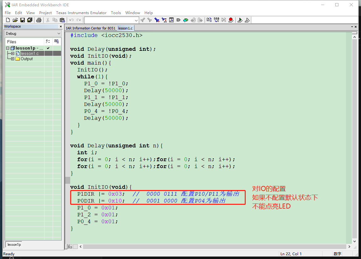
void InitIO(void){
  P1DIR |= 0x03;  // 0000 0111 配置P10/P11为输出
  P0DIR |= 0x10;  // 0001 0000 配置P04为输出
  P1_0 = 0x01;
  P1_2 = 0x01;
  P0_4 = 0x01;
}
#include <iocc2530.h>
//点亮LED(库函数版)
void Delay(unsigned int n);
void InitIO(void);
void SetLed(int LedId,int state);
void main(void){
  InitIO();
  while(1){
    SetLed(0,0);
    Delay(50000);
    SetLed(1,0);
    Delay(50000);
    SetLed(2,0);
    Delay(50000);

    SetLed(0,1);
    Delay(50000);
    SetLed(1,1);
    Delay(50000);
    SetLed(2,1);
    Delay(50000);


  }
}

void Delay(unsigned int n){//这里定时多久不重要,重要的是有定时时间
  int i;
  for(i=0; i<n; i++);for(i=0; i<n; i++);
  for(i=0; i<n; i++);for(i=0; i<n; i++);
}

void InitIO(void){
  P1DIR |= 0x03;  // 0000 0111 配置P10/P11为输出
  P0DIR |= 0x10;  // 0001 0000 配置P04为输出
  P1_0 = 0x01;
  P1_2 = 0x01;
  P0_4 = 0x01;
}

void SetLed(int LedId,int state){//上拉给0点亮
  if(LedId == 0){//P1_0
    if(state == 0) P1_0 = 0;
    else           P1_0 = 1;
  }
  if(LedId == 1){//P1_1
    if(state == 0) P1_1 = 0;
    else           P1_1 = 1;
  }
  if(LedId == 2){//P0_4
    if(state == 0) P0_4 = 0;
    else           P0_4 = 1;
  }
}
和keil开发类似,也要包含头文件和main主函数
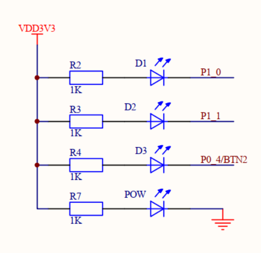
然后看自己CC2530的开发板原理图,找一下LED的位置,直接寄存器赋值将其点亮
烧录程序
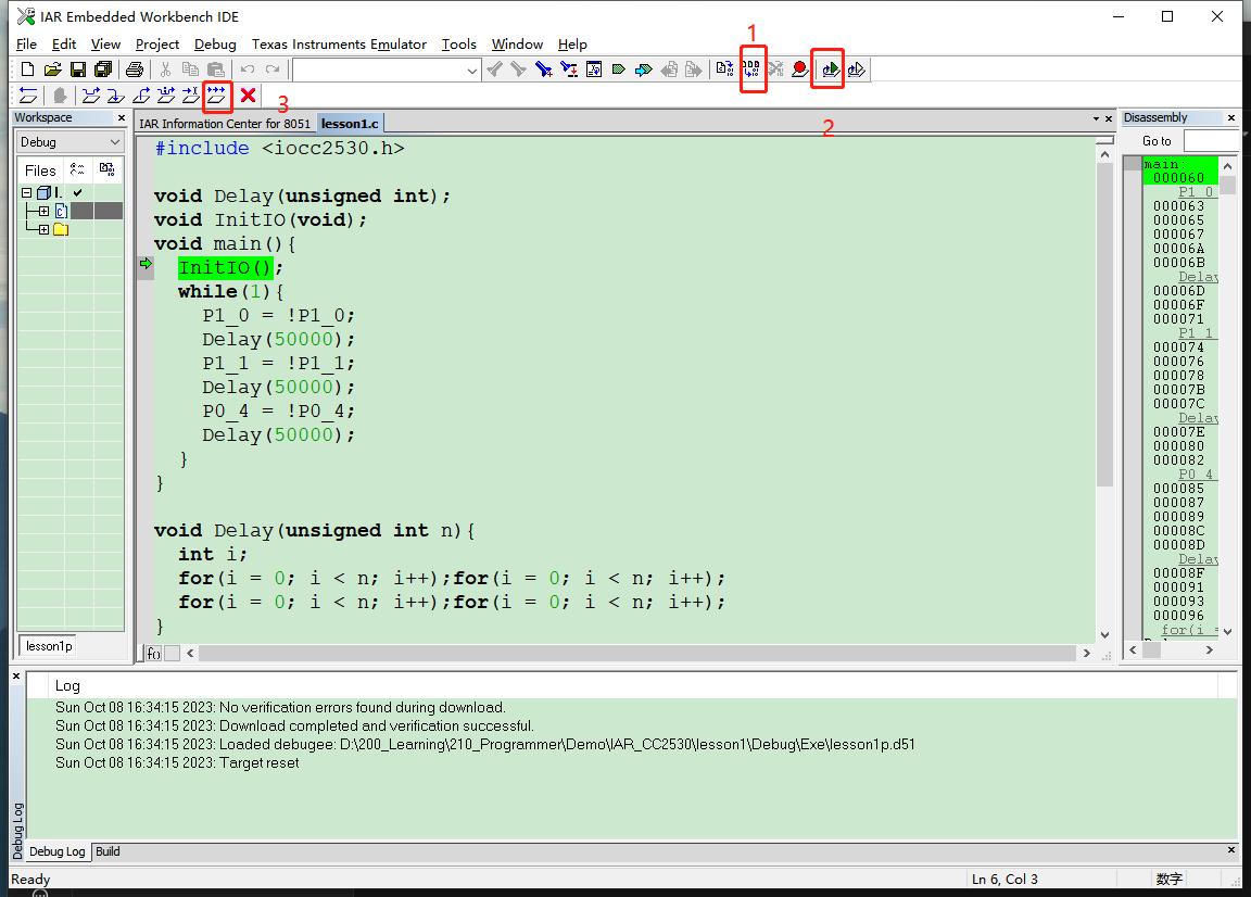
需要用到硬件仿真器连接,连接后按一下按钮(相当于reset?)
电脑上要安装好驱动,没有驱动识别不出来
IO配置
工作范围:2-3.6v,推荐3.3v
封装:QFN40,40引脚
ZigBee的IO口可以有不同的工作模式,所以在用之前,需要先学会IO口怎么配置
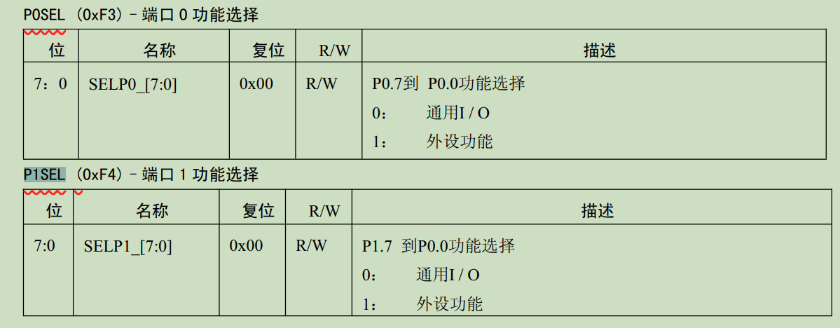
①普通IO模式与片上外设模式—寄存器— P0SEL、P1SEL、P2SEL
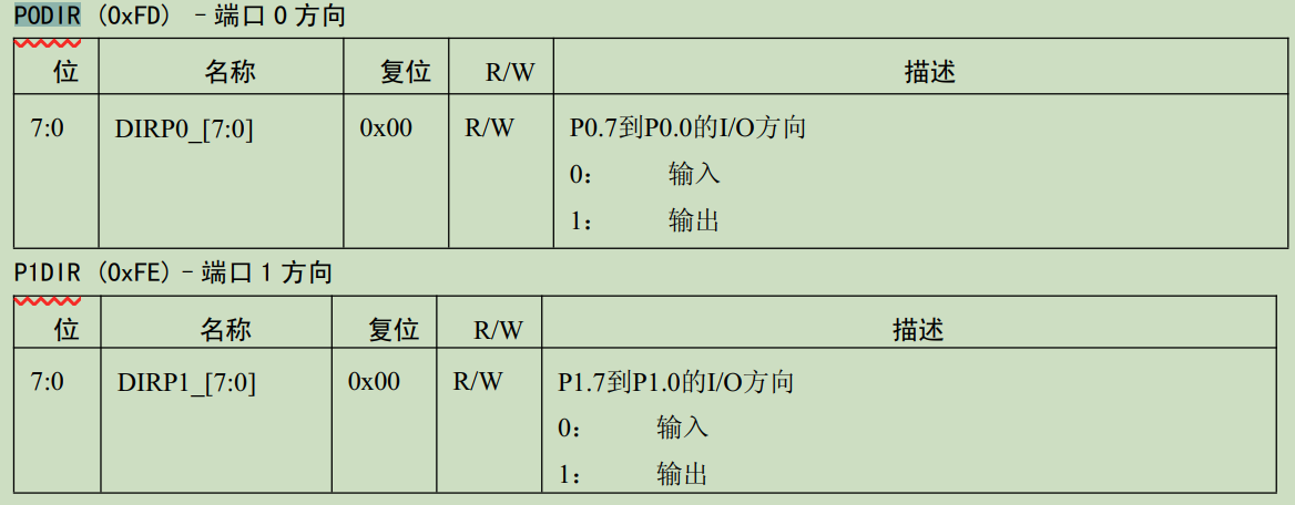
②输出状态与输入状态—寄存器—P0DIR、P1DIR、P2DIR
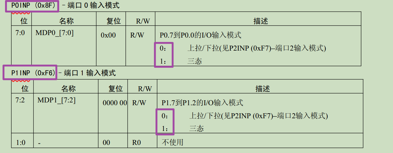
③上拉下拉三态——PxINP(P0INP、P1INP、P2INP)
①板子上电初始化默认处于普通IO模式,即P0SEL、P1SEL、P2SEL均为0x00,如果没有用到片上外设,可以不写关于PxSEL的配置:
②
③如果PxINP的第六位为0,那么P06一定是三态,如果是0,那么处于上拉或下拉 (由P2INP的高三位决定此时处于上拉还是下拉的状态。)
