前言
这一期我们简单介绍一下SPI协议,然后我们学习一下矩阵键盘,了解EEPROM是干什么用的,话不多说,开整!
SPI协议
SPI(Serial Peripheral Interface)是一种同步串行通信协议,用于在嵌入式系统中连接微控制器(MCU)和外围设备(如传感器、存储器、显示器等)。SPI协议需要4根线进行数据传输,分别是:
- SCLK:时钟信号线,由主设备控制时序,用于同步数据传输。
- MOSI:主设备输出从设备输入线,主设备通过该线向从设备发送数据。
- MISO:主设备输入从设备输出线,从设备通过该线向主设备发送数据。
- SS:从设备片选线,用于选择与主设备通信的从设备。(其他叫法CS)
SPI协议支持全双工通信,意味着主设备和从设备可以同时发送和接收数据。SPI协议传输数据时采用的是先进先出的方式。
标准的SPI总共有4根线,包括:SCLK(时钟线)、MOSI(主机输出从机输入线)、MISO(主机输入从机输出线)和SS(片选线)。但是在实际的应用中,可能会根据需要添加其他的辅助信号线,如数据就绪信号等。因此,SPI的具体实现方式可能会有所不同。
SPI协议中的DC线是指数据/命令线(Data/Command line),有时也称作RS线(Register Select line)。它是用来控制从主设备到从设备传输的数据是命令还是普通数据的信号线。在许多液晶显示屏、OLED屏幕、触摸屏等设备中,SPI总线上的DC线通常用于指示传输的数据是图像数据还是命令数据,以便设备能够正确地解析和处理数据
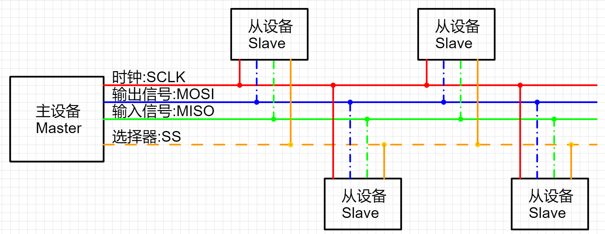
SPI通讯的时序是由主设备(Master)发起的,在数据传输的过程中,需要进行时序的协调,具体流程如下:
- 主设备(Master)通过片选信号(Slave Select)选择通信的从设备(Slave)。
- 主设备(Master)向从设备(Slave)发送时钟信号(SCLK),并将数据从输出口(MOSI)发送到从设备(Slave)的输入口(MISO)。
- 从设备(Slave)在每个时钟脉冲的下降沿采样输入口(MISO)的数据,并将数据从输出口(MOSI)发送回主设备(Master)的输入口(MISO)。
- 当传输完成后,主设备(Master)取消片选信号(Slave Select),从设备(Slave)被释放。
具体的通讯流程时序可以根据实际应用情况进行调整,例如可以调整时钟信号的极性和相位、选择合适的时钟频率等。
矩阵键盘
简介
矩阵键盘是一种常见的数字输入设备,由多行多列的按键组成。每个按键都有一个唯一的行列坐标,通过行列坐标可以确定按键的编号,从而实现对数字或字母的输入。
原理图
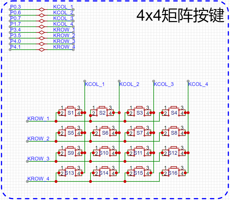
矩阵键盘的基本结构包括按键、行引脚和列引脚。按键一般是机械按键或触摸按键,行引脚和列引脚分别与矩阵键盘的行和列相连,用于检测按键的输入状态。
代码
因为矩阵按键和之前学的独立按键很相似,所以代码不做过多解析,基本注释都在代码上标明,我们直接通过位运算来设定中间值从而捕获到每个按键的状态。
获取按键状态
#include "GPIO.h"
#include "NVIC.h"
#include "Delay.h"
#include "UART.h"
#include "Switch.h"

#define COL1 P03
#define COL2 P06
#define COL3 P07
#define COL4 P17

#define ROW1 P34
#define ROW2 P35
#define ROW3 P40
#define ROW4 P41

//判断按键的状态
#define IS_KEY_DOWN(row , col)  ((states & (1 << (row * 4 + col))) == 0)
#define IS_KEY_UP(row,col) ((states  & (1 << (row * 4 + col))) > 0)

//设置按键的状态
#define SET_KEY_DOWN(row, col)   (states &= ~(1 << (row * 4 + col)))
#define SET_KEY_UP(row, col)  (states  |=  (1 << (row * 4 + col)))

//按键的状态
#define DOWN 0
#define UP 1

void GPIO_config(void) {
	GPIO_InitTypeDef	GPIO_InitStructure;		//结构定义
	GPIO_InitStructure.Pin  = GPIO_Pin_3 | GPIO_Pin_6 | GPIO_Pin_7;		//指定要初始化的IO,
	GPIO_InitStructure.Mode = GPIO_PullUp;	//指定IO的输入或输出方式,GPIO_PullUp,GPIO_HighZ,GPIO_OUT_OD,GPIO_OUT_PP
	GPIO_Inilize(GPIO_P0, &GPIO_InitStructure);//初始化

	GPIO_InitStructure.Pin  =  GPIO_Pin_7;		//指定要初始化的IO,
	GPIO_InitStructure.Mode = GPIO_PullUp;	//指定IO的输入或输出方式,GPIO_PullUp,GPIO_HighZ,GPIO_OUT_OD,GPIO_OUT_PP
	GPIO_Inilize(GPIO_P1, &GPIO_InitStructure);//初始化

	GPIO_InitStructure.Pin  =  GPIO_Pin_4  | GPIO_Pin_5;		//指定要初始化的IO,
	GPIO_InitStructure.Mode = GPIO_PullUp;	//指定IO的输入或输出方式,GPIO_PullUp,GPIO_HighZ,GPIO_OUT_OD,GPIO_OUT_PP
	GPIO_Inilize(GPIO_P3, &GPIO_InitStructure);//初始化

	GPIO_InitStructure.Pin  =  GPIO_Pin_0  | GPIO_Pin_1;		//指定要初始化的IO,
	GPIO_InitStructure.Mode = GPIO_PullUp;	//指定IO的输入或输出方式,GPIO_PullUp,GPIO_HighZ,GPIO_OUT_OD,GPIO_OUT_PP
	GPIO_Inilize(GPIO_P4, &GPIO_InitStructure);//初始化
}

void UART_config(void) {
	// >>> 记得添加 NVIC.c, UART.c, UART_Isr.c <<<
    COMx_InitDefine		COMx_InitStructure;					//结构定义
    COMx_InitStructure.UART_Mode      = UART_8bit_BRTx;	//模式, UART_ShiftRight,UART_8bit_BRTx,UART_9bit,UART_9bit_BRTx
    COMx_InitStructure.UART_BRT_Use   = BRT_Timer1;			//选择波特率发生器, BRT_Timer1, BRT_Timer2 (注意: 串口2固定使用BRT_Timer2)
    COMx_InitStructure.UART_BaudRate  = 115200ul;			//波特率, 一般 110 ~ 115200
    COMx_InitStructure.UART_RxEnable  = ENABLE;				//接收允许,   ENABLE或DISABLE
    COMx_InitStructure.BaudRateDouble = DISABLE;			//波特率加倍, ENABLE或DISABLE
    UART_Configuration(UART1, &COMx_InitStructure);		//初始化串口1 UART1,UART2,UART3,UART4

  	NVIC_UART1_Init(ENABLE,Priority_1);		//中断使能, ENABLE/DISABLE; 优先级(低到高) Priority_0,Priority_1,Priority_2,Priority_3
    UART1_SW(UART1_SW_P30_P31);		// 引脚选择, UART1_SW_P30_P31,UART1_SW_P36_P37,UART1_SW_P16_P17,UART1_SW_P43_P44
}

u8 get_col(u8 i){
	if(i==0) return COL1;
	if(i==1) return COL2;
	if(i==2) return COL3;
	if(i==3) return COL4;
	return COL1;
}

// 根据遍历的索引下标来拉低对应行的电平状态
void pull_row(u8 i){
	ROW1 = i == 0 ? 0 : 1;
	ROW2 = i == 1 ? 0 : 1;
	ROW3 = i == 2 ? 0 : 1;
	ROW4 = i == 3 ? 0 : 1;
}


u16 states = 0xFFFF;  //1111 1111 1111 1111


void main(){
	int i , j;
	EA = 1 ;

	GPIO_config();

	UART_config();

	printf("start...\n");

	while(1){

		// 判定4行的状态

		//外层循环控制的是:行
		for(i  = 0 ; i < 4 ; i++){

			// 每遍历一次,就拉低这一行对应的电平状态,拉高其他行的电平状态
			pull_row(i);

			//里层循环控制的是: 列
			for(j = 0 ; j < 4  ; j++){

				/*
					 第1行:
							0-0 :  字节的 第 0 位
							0-1 :  字节的 第 1 位
							0-2 :  字节的 第 2 位
							0-3 :  字节的 第 3 位

					第2行:
							1-0 :  字节的 第 4 位
							1-1 :  字节的 第 5 位
							1-2 :  字节的 第 6 位
							1-3 :  字节的 第 7 位

					第3行:
							2-0 :  字节的 第 8 位
							2-1 :  字节的 第 9 位
							2-2 :  字节的 第 10 位
							2-3 :  字节的 第 11 位

					第4行:
							3-0 :  字节的 第 12 位
							3-1 :  字节的 第 13 位
							3-2 :  字节的 第 14 位
							3-3 :  字节的 第 15 位

					所以i行j列的键,对应的 位是: i * 4 + j
					我们要去操作对应的键和位。
				*/


				if(get_col(j) == UP && IS_KEY_DOWN(i, j)){
					printf("%d-%d::弹起\n" , i+1 , j+1);
					SET_KEY_UP(i, j);
				}else if(get_col(j) == DOWN && IS_KEY_UP(i,j) ){
					printf("%d-%d::按下\n" , i+1 , j+1);
					SET_KEY_DOWN(i,j);
				}
			}
		}


		delay_ms(10);
	}
}
获取按键状态(通过extern封装)
main.c
#include "GPIO.h"
#include "NVIC.h"
#include "Delay.h"
#include "UART.h"
#include "Switch.h"
#include "MatrixKey.h"


void UART_config(void) {
	// >>> 记得添加 NVIC.c, UART.c, UART_Isr.c <<<
    COMx_InitDefine		COMx_InitStructure;					//结构定义
    COMx_InitStructure.UART_Mode      = UART_8bit_BRTx;	//模式, UART_ShiftRight,UART_8bit_BRTx,UART_9bit,UART_9bit_BRTx
    COMx_InitStructure.UART_BRT_Use   = BRT_Timer1;			//选择波特率发生器, BRT_Timer1, BRT_Timer2 (注意: 串口2固定使用BRT_Timer2)
    COMx_InitStructure.UART_BaudRate  = 115200ul;			//波特率, 一般 110 ~ 115200
    COMx_InitStructure.UART_RxEnable  = ENABLE;				//接收允许,   ENABLE或DISABLE
    COMx_InitStructure.BaudRateDouble = DISABLE;			//波特率加倍, ENABLE或DISABLE
    UART_Configuration(UART1, &COMx_InitStructure);		//初始化串口1 UART1,UART2,UART3,UART4

  	NVIC_UART1_Init(ENABLE,Priority_1);		//中断使能, ENABLE/DISABLE; 优先级(低到高) Priority_0,Priority_1,Priority_2,Priority_3
    UART1_SW(UART1_SW_P30_P31);		// 引脚选择, UART1_SW_P30_P31,UART1_SW_P36_P37,UART1_SW_P16_P17,UART1_SW_P43_P44
}


void MK_keydown(u8 row , u8 col){
	printf("%d-%d  按键按下了..\n" , (int)row , (int)col);
}

void MK_keyup(u8 row , u8 col){
		printf("%d-%d  按键弹起了..\n" , (int)row , (int)col);
}


void main(){


	EA = 1 ;

	//初始化矩阵键盘
	MK_init();

	UART_config();

	printf("start...\n");


	while(1){

		//扫描键盘
		MK_scan();


		delay_ms(10);
	}
}
MatrixKey.h
#ifndef	__MATRIXKEY_H
#define	__MATRIXKEY_H

#include "GPIO.h"

// 声明: 宏、结构体
#define COL1 P03
#define COL2 P06
#define COL3 P07
#define COL4 P17

#define ROW1 P34
#define ROW2 P35
#define ROW3 P40
#define ROW4 P41

//判断按键的状态
#define IS_KEY_DOWN(row , col)  ((states & (1 << (row * 4 + col))) == 0)
#define IS_KEY_UP(row,col) ((states  & (1 << (row * 4 + col))) > 0)


//设置按键的状态
#define SET_KEY_DOWN(row, col)   (states &= ~(1 << (row * 4 + col)))
#define SET_KEY_UP(row, col)  (states  |=  (1 << (row * 4 + col)))

//按键的状态
#define DOWN 0
#define UP 1


// 函数具体功能
void MK_init();

//扫描按键的状态的函数
void MK_scan();


//既然封装了按键的扫描功能,但是以后按键按下了,或者弹起了,用户有自己的想法
//它们需求千变万化,所以特地声明了两个extern 标记的函数,谁要是使用我们的这一套代码
//就需要在自己的代码里面实现|定义这两个函数,这样就可以捕捉到是按下了按键还是弹起了按键。
//就可以针对性的去处理了。
extern void MK_keydown(u8 row , u8 col);

extern void MK_keyup(u8 row , u8 col);


#endif
MatrixKey.c
#include "MatrixKey.h"

u16 states = 0xFFFF;  //1111 1111 1111 1111

void MK_init(){
  GPIO_InitTypeDef	GPIO_InitStructure;		//结构定义
	GPIO_InitStructure.Pin  = GPIO_Pin_3 | GPIO_Pin_6 | GPIO_Pin_7;		//指定要初始化的IO,
	GPIO_InitStructure.Mode = GPIO_PullUp;	//指定IO的输入或输出方式,GPIO_PullUp,GPIO_HighZ,GPIO_OUT_OD,GPIO_OUT_PP
	GPIO_Inilize(GPIO_P0, &GPIO_InitStructure);//初始化

	GPIO_InitStructure.Pin  =  GPIO_Pin_7;		//指定要初始化的IO,
	GPIO_InitStructure.Mode = GPIO_PullUp;	//指定IO的输入或输出方式,GPIO_PullUp,GPIO_HighZ,GPIO_OUT_OD,GPIO_OUT_PP
	GPIO_Inilize(GPIO_P1, &GPIO_InitStructure);//初始化

	GPIO_InitStructure.Pin  =  GPIO_Pin_4  | GPIO_Pin_5;		//指定要初始化的IO,
	GPIO_InitStructure.Mode = GPIO_PullUp;	//指定IO的输入或输出方式,GPIO_PullUp,GPIO_HighZ,GPIO_OUT_OD,GPIO_OUT_PP
	GPIO_Inilize(GPIO_P3, &GPIO_InitStructure);//初始化


	GPIO_InitStructure.Pin  =  GPIO_Pin_0  | GPIO_Pin_1;		//指定要初始化的IO,
	GPIO_InitStructure.Mode = GPIO_PullUp;	//指定IO的输入或输出方式,GPIO_PullUp,GPIO_HighZ,GPIO_OUT_OD,GPIO_OUT_PP
	GPIO_Inilize(GPIO_P4, &GPIO_InitStructure);//初始化
}

u8 get_col(u8 i){
	if(i==0) return COL1;
	if(i==1) return COL2;
	if(i==2) return COL3;
	if(i==3) return COL4;
	return COL1;
}

// 根据遍历的索引下标来拉低对应行的电平状态
void pull_row(u8 i){
	ROW1 = i == 0 ? 0 : 1;
	ROW2 = i == 1 ? 0 : 1;
	ROW3 = i == 2 ? 0 : 1;
	ROW4 = i == 3 ? 0 : 1;
}

void MK_scan(){
	u8 i , j;
	// 判定4行的状态

		//外层循环控制的是:行
		for(i  = 0 ; i < 4 ; i++){

			// 每遍历一次,就拉低这一行对应的电平状态,拉高其他行的电平状态
			pull_row(i);

			//里层循环控制的是: 列
			for(j = 0 ; j < 4  ; j++){
				if(get_col(j) == UP && IS_KEY_DOWN(i, j)){
					SET_KEY_UP(i, j);

					 MK_keyup(i, j);
				}else if(get_col(j) == DOWN && IS_KEY_UP(i,j) ){
					SET_KEY_DOWN(i,j);

					MK_keydown(i ,j);
				}
			}
		}
}
获取按键状态(通过函数指针封装)
main.c
#include "Delay.h"
#include "NVIC.h"
#include "GPIO.h"
#include "UART.h"
#include "Switch.h"
#include "MKkey.h"

void UART_config(void) {
	// >>> 记得添加 NVIC.c, UART.c, UART_Isr.c <<<
    COMx_InitDefine		COMx_InitStructure;					//结构定义
    COMx_InitStructure.UART_Mode      = UART_8bit_BRTx;	//模式, UART_ShiftRight,UART_8bit_BRTx,UART_9bit,UART_9bit_BRTx
    COMx_InitStructure.UART_BRT_Use   = BRT_Timer1;			//选择波特率发生器, BRT_Timer1, BRT_Timer2 (注意: 串口2固定使用BRT_Timer2)
    COMx_InitStructure.UART_BaudRate  = 115200ul;			//波特率, 一般 110 ~ 115200
    COMx_InitStructure.UART_RxEnable  = ENABLE;				//接收允许,   ENABLE或DISABLE
    COMx_InitStructure.BaudRateDouble = DISABLE;			//波特率加倍, ENABLE或DISABLE
    UART_Configuration(UART1, &COMx_InitStructure);		//初始化串口1 UART1,UART2,UART3,UART4

  	NVIC_UART1_Init(ENABLE,Priority_1);		//中断使能, ENABLE/DISABLE; 优先级(低到高) Priority_0,Priority_1,Priority_2,Priority_3
    UART1_SW(UART1_SW_P30_P31);		// 引脚选择, UART1_SW_P30_P31,UART1_SW_P36_P37,UART1_SW_P16_P17,UART1_SW_P43_P44
}

void keydown(u8 row,u8 col){
	printf("%d-%d:按下\n",(int)row+1,(int)col+1);
}

void keyup(u8 row,u8 col){
	printf("%d-%d:弹起\n",(int)row+1,(int)col+1);
}


void main(){

	EA = 1;
	KEY_init();
	UART_config();

	while(1){

		MK_GET_key(keydown,keyup);
		delay_ms(10);

	}
}
MKkey.h
#ifndef	__MKkey_H
#define	__MKkey_H

#include "GPIO.h"

#define COL1 P03
#define COL2 P06
#define COL3 P07
#define COL4 P17

#define ROW1 P34
#define ROW2 P35
#define ROW3 P40
#define ROW4 P41


#define IS_KEY_DOWN(row,col) ((states & (1<<(row * 4 + col))) == 0)
#define IS_KEY_UP(row,col) ((states & (1<<(row * 4 + col))) > 0)
#define SET_KEY_DOWN(row,col) (states &= ~((1<<(row * 4 + col))))
#define SET_KEY_UP(row,col) (states |= (1<<(row * 4 + col)))
#define DOWN 0
#define UP 1


void KEY_init();

void MK_GET_key(void(*keydown)(u8 row,u8 col),void(*keyup)(u8 row,u8 col));

#endif
MKkey.c
#include "MKkey.h"

u16 states = 0xffff;

void KEY_init(){
	GPIO_InitTypeDef	GPIO_InitStructure;		//结构定义
	GPIO_InitStructure.Pin  = GPIO_Pin_3 | GPIO_Pin_6 | GPIO_Pin_7;		//指定要初始化的IO,
	GPIO_InitStructure.Mode = GPIO_PullUp;	//指定IO的输入或输出方式,GPIO_PullUp,GPIO_HighZ,GPIO_OUT_OD,GPIO_OUT_PP
	GPIO_Inilize(GPIO_P0, &GPIO_InitStructure);//初始化

	GPIO_InitStructure.Pin  = GPIO_Pin_7;		//指定要初始化的IO,
	GPIO_InitStructure.Mode = GPIO_PullUp;	//指定IO的输入或输出方式,GPIO_PullUp,GPIO_HighZ,GPIO_OUT_OD,GPIO_OUT_PP
	GPIO_Inilize(GPIO_P1, &GPIO_InitStructure);//初始化

	GPIO_InitStructure.Pin  = GPIO_Pin_4 | GPIO_Pin_5;		//指定要初始化的IO,
	GPIO_InitStructure.Mode = GPIO_PullUp;	//指定IO的输入或输出方式,GPIO_PullUp,GPIO_HighZ,GPIO_OUT_OD,GPIO_OUT_PP
	GPIO_Inilize(GPIO_P3, &GPIO_InitStructure);//初始化

	GPIO_InitStructure.Pin  = GPIO_Pin_0 | GPIO_Pin_1;		//指定要初始化的IO,
	GPIO_InitStructure.Mode = GPIO_PullUp;	//指定IO的输入或输出方式,GPIO_PullUp,GPIO_HighZ,GPIO_OUT_OD,GPIO_OUT_PP
	GPIO_Inilize(GPIO_P4, &GPIO_InitStructure);//初始化
}

u8 get_key(u8 i){
	if(i==0) return COL1;
	if(i==1) return COL2;
	if(i==2) return COL3;
	if(i==3) return COL4;
	return COL1;

}

void key_down(u8 i){
	ROW1 = i == 0 ? 0 : 1;
	ROW2 = i == 1 ? 0 : 1;
	ROW3 = i == 2 ? 0 : 1;
	ROW4 = i == 3 ? 0 : 1;
}

void MK_GET_key(void(*keydown)(u8 row,u8 col),void(*keyup)(u8 row,u8 col)){
		int i,j;
	for(i=0;i<4;i++){
			key_down(i);
			for(j=0;j<4;j++){
				if(get_key(j) == UP && IS_KEY_DOWN(i,j)){

						SET_KEY_UP(i,j);
					if(keyup!=NULL){
					keyup(i,j);
					}

				}else if(get_key(j) == DOWN && IS_KEY_UP(i,j)){

					SET_KEY_DOWN(i,j);
					if(keydown!=NULL){
					keydown(i,j);
					}

				}
			}

		}
}
EEPROM
简介
EEPROM是一种可擦写可编程只读存储器(Electrically Erasable Programmable Read-Only Memory)的缩写。它是一种非易失性存储器,可以在不需要外部电源的情况下保持存储数据。与ROM不同,EEPROM可以通过电子擦除和编程来修改存储的数据,因此它是一种可重写的存储器。
EEPROM通常用于存储需要频繁修改的数据,例如系统配置信息、用户设置、校准数据等。由于EEPROM可以在系统运行时进行读写操作,因此它在许多应用中都具有很高的实用价值。
设置EEPROM
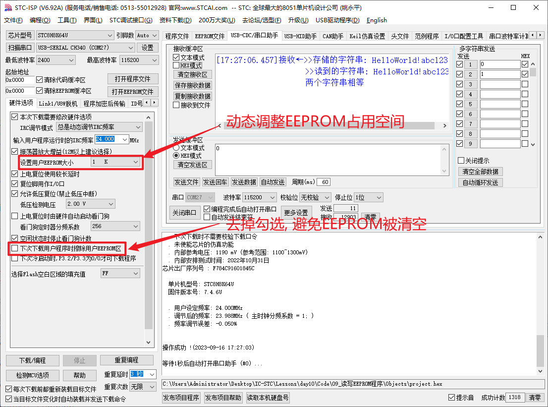
TC8H8K64U的EEPROM可以在烧录的时候指定大小, 如下图
代码
#include "Delay.h"
#include "NVIC.h"
#include "UART.h"
#include "Switch.h"
#include "EEPROM.h"
#include "string.h"

void UART_config(void) {
	// >>> 记得添加 NVIC.c, UART.c, UART_Isr.c <<<
    COMx_InitDefine		COMx_InitStructure;					//结构定义
    COMx_InitStructure.UART_Mode      = UART_8bit_BRTx;	//模式, UART_ShiftRight,UART_8bit_BRTx,UART_9bit,UART_9bit_BRTx
    COMx_InitStructure.UART_BRT_Use   = BRT_Timer1;			//选择波特率发生器, BRT_Timer1, BRT_Timer2 (注意: 串口2固定使用BRT_Timer2)
    COMx_InitStructure.UART_BaudRate  = 115200ul;			//波特率, 一般 110 ~ 115200
    COMx_InitStructure.UART_RxEnable  = ENABLE;				//接收允许,   ENABLE或DISABLE
    COMx_InitStructure.BaudRateDouble = DISABLE;			//波特率加倍, ENABLE或DISABLE
    UART_Configuration(UART1, &COMx_InitStructure);		//初始化串口1 UART1,UART2,UART3,UART4

  	NVIC_UART1_Init(ENABLE,Priority_1);		//中断使能, ENABLE/DISABLE; 优先级(低到高) Priority_0,Priority_1,Priority_2,Priority_3
    UART1_SW(UART1_SW_P30_P31);		// 引脚选择, UART1_SW_P30_P31,UART1_SW_P36_P37,UART1_SW_P16_P17,UART1_SW_P43_P44
}

u16 EE_address = 0x0000;
xdata	char  str2[100];

void main(){

	char *  str = "helloworld";


	u16 len  =  strlen(str);

	EA = 1 ;
	UART_config();

	//=============================操作EEPROM==========================

	//1. 擦除EPPROM :: 擦除的起始地址
	EEPROM_SectorErase(EE_address);

	//2. 写数据参数一: 写入的起始地址 ,参数二: 写什么数据,参数三,写多少个长度
	EEPROM_write_n(EE_address,str,len);

	//3. 读数据参数一: 读取的起始地址 ,参数二: 读取到哪里,参数三,读多少个长度
	EEPROM_read_n(EE_address,str2,len);


	//因为使用的字符数组来接收数据,它的长度很长,我们需要去设置字符的截止符号
	str2[len] = '\0';

	printf("str2=%s\n" , str2);


	while(1){

	}
}
总结
今天内容比较容易,但是小伙伴们也一定要多加练习,在验证eeprom时,可以通过以上代码将数据写入进去,然后进行断电重新上电,直接进行读的操作,就会发现我们之前写上的数据仍然可以读取出来,说明数据被我们写里面存储啦。下期再见!


