文章目录
- 前言
- 一、在Shader中,手动把正交相机的坐标转化到裁剪空间
- 1、我们在属性面板定义一个变量,用于传入摄像机的信息
- 2、获取h、r、w、n、f
- 3、获取OpenGL下的转化矩阵
- 4、 获取DirectX下的转化矩阵
- 5、手动将观察空间下的坐标转换到裁剪空间下
- 6、这里为测试模型效果,进行了纹理采样(可选)
- 二、最终效果
- 1、OpenGL下:
- 2、DirectX下(需要注意的是,在DX平台下屏幕的 y 坐标是相反的,需要在转化矩阵的 y 对应位置乘以 -1):
- 3、可以使用 UNITY_NEAR_CLIP_VALUE 来判断是什么平台
- 4、最终代码
前言
我们在上一篇文章中,进行了正交相机视图空间下转化到裁剪空间下的矩阵推导。
- Unity中Shader裁剪空间推导(正交相机到裁剪空间的转化矩阵)
我们在这篇文章中,在Unity的Shader中实现一下。
一、在Shader中,手动把正交相机的坐标转化到裁剪空间
- OpenGL下:
[ 2 w 0 0 0 0 2 h 0 0 0 0 2 n − f n + f n − f 0 0 0 1 ] \begin{bmatrix} \frac{2}{w} & 0 & 0 & 0 \\ 0 & \frac{2}{h} & 0 &0\\ 0 & 0 & \frac{2}{n -f} &\frac{n + f}{n - f}\\ 0 & 0 & 0 & 1\\ \end{bmatrix} w20000h20000n−f2000n−fn+f1
- DirectX下:
[ 2 w 0 0 0 0 2 h 0 0 0 0 1 n − f n n − f 0 0 0 1 ] \begin{bmatrix} \frac{2}{w} & 0 & 0 & 0 \\ 0 & \frac{2}{h} & 0 &0\\ 0 & 0 & \frac{1}{n -f} &\frac{n}{n - f}\\ 0 & 0 & 0 & 1\\ \end{bmatrix} w20000h20000n−f1000n−fn1
- ReversedZ
在DirectX中,因为精度问题
会把原本的范围从[0,1]修改为[1,0]。所以,矩阵需要按照之前的方法重新推导
[
2
w
0
0
0
0
2
h
0
0
0
0
1
f
−
n
f
f
−
n
0
0
0
1
]
\begin{bmatrix} \frac{2}{w} & 0 & 0 & 0 \\ 0 & \frac{2}{h} & 0 &0\\ 0 & 0 & \frac{1}{f-n} &\frac{f}{f-n}\\ 0 & 0 & 0 & 1\\ \end{bmatrix}
w20000h20000f−n1000f−nf1
1、我们在属性面板定义一个变量,用于传入摄像机的信息
这里信息包括:
摄像机的Size(X)、近裁剪面(Y)、远裁剪面(Z) 和 屏幕宽高比(W)
1.7777……是 1920 / 1080 的比值。
_CameraParams(“Size(X),Near(Y),Far(Z) Ratio(W)”,Vector) = (0,0,0,1.777)
2、获取h、r、w、n、f
float h = _CameraParams.x * 2;
float w = h * _CameraParams.w;
float n = _CameraParams.y;
float f = _CameraParams.z;
3、获取OpenGL下的转化矩阵
//OpenGL
float4x4 M_clip01 = float4x4
(
	2/w,0,0,0,
	0,2/h,0,0,
	0,0,2/(n - f),(n + f) / (n - f),
	0,0,0,1
);
4、 获取DirectX下的转化矩阵
//DirectX
float4x4 M_clip02 = float4x4
(
	2/w,0,0,0,
	0,2/h,0,0,
	0,0,1/(f-n),f/(f-n),
	0,0,0,1
);
5、手动将观察空间下的坐标转换到裁剪空间下
//手动将观察空间下的坐标转换到裁剪空间下
o.vertexCS = mul(M_clip01,float4(vertexVS,1));
6、这里为测试模型效果,进行了纹理采样(可选)
- 属性面板接收纹理
_MainTex(“MainTex”,2D) = “white”{}
- 定义纹理 和 采样器
TEXTURE2D(_MainTex);
SAMPLER(sampler_MainTex);
- 在片元着色器中,采样并且使用
float4 mainTex = SAMPLE_TEXTURE2D(_MainTex,sampler_MainTex,i.uv);
return mainTex;
二、最终效果
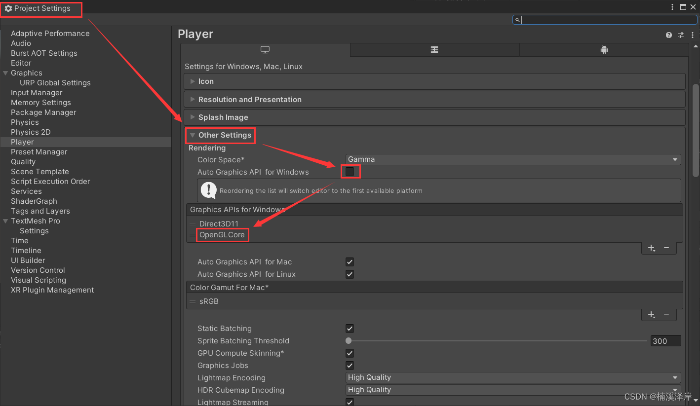
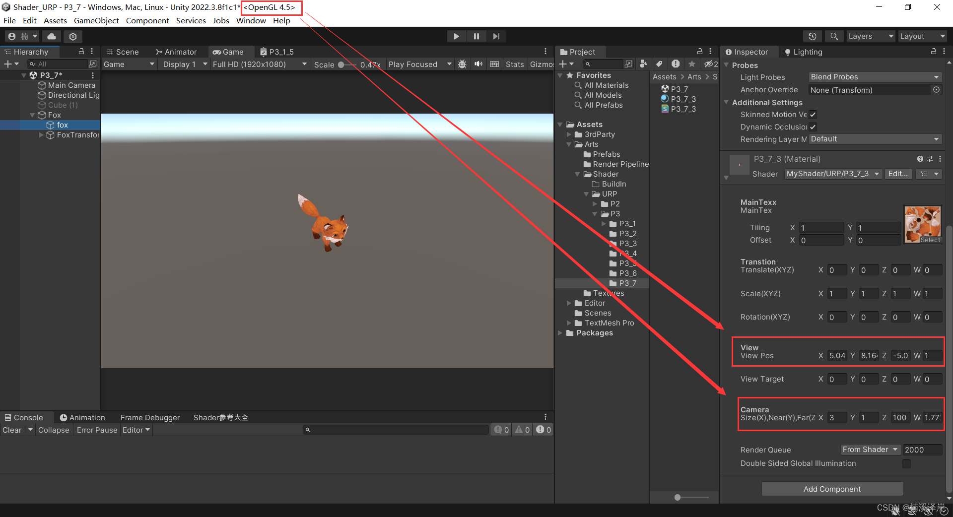
1、OpenGL下:
- Edit->ProjectSetting->Player 中修改项目渲染平台设置
//手动将观察空间下的坐标转换到裁剪空间下
o.vertexCS = mul(M_clip01,float4(vertexVS,1));
- 传入当前摄像机信息
2、DirectX下(需要注意的是,在DX平台下屏幕的 y 坐标是相反的,需要在转化矩阵的 y 对应位置乘以 -1):
- Edit->ProjectSetting->Player 中修改项目渲染平台设置
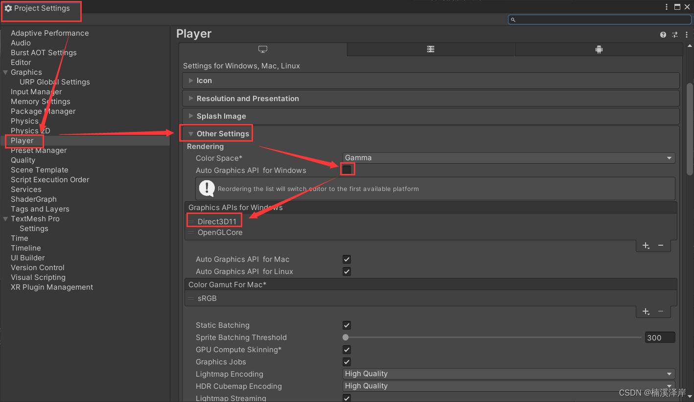
//手动将观察空间下的坐标转换到裁剪空间下
o.vertexCS = mul(M_clip02,float4(vertexVS,1));
- 传入当前摄像机信息
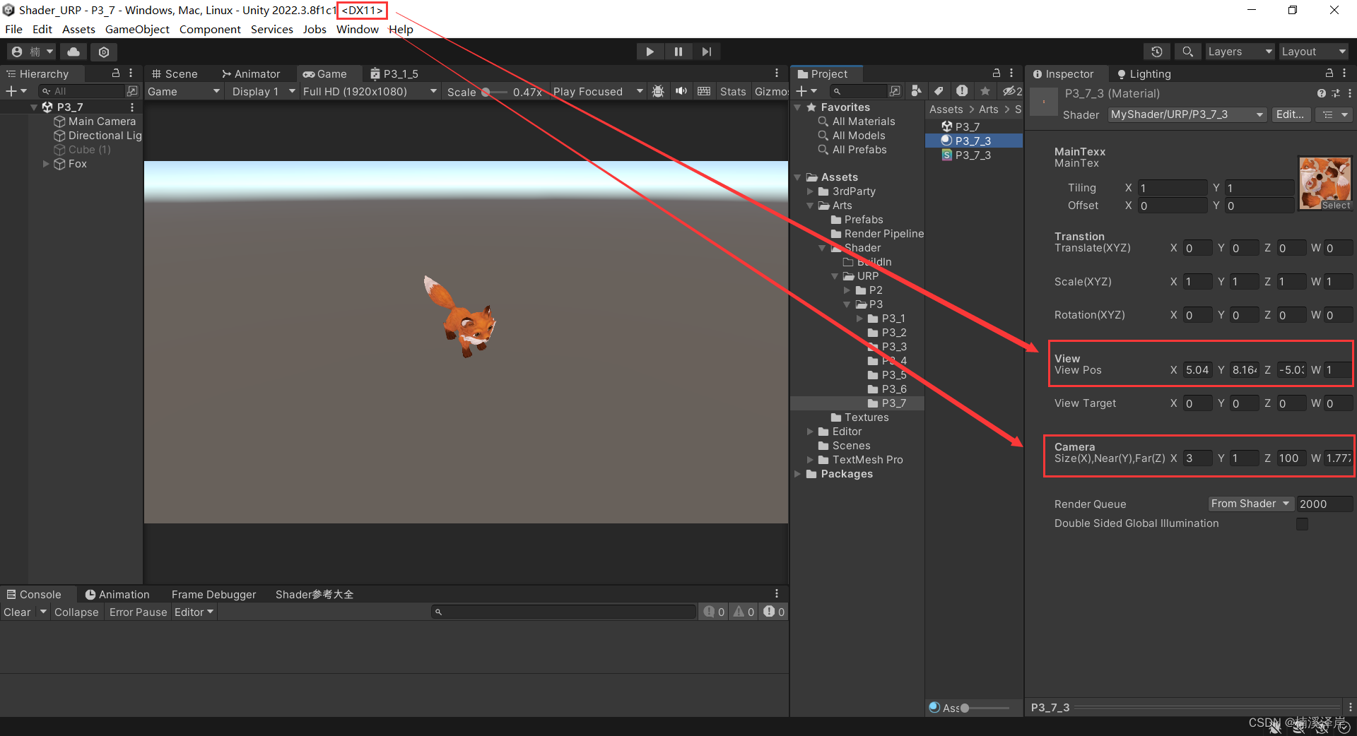
3、可以使用 UNITY_NEAR_CLIP_VALUE 来判断是什么平台
裁剪空间下的近剪裁值,(DX为1,OpenGL为-1).
4、最终代码
//平移变换
//缩放变换
//旋转变换(四维)
//视图空间矩阵
//正交相机视图空间 -> 裁剪空间
Shader "MyShader/URP/P3_7_3"
{
    Properties
    {
        [Header(MainTexx)]
        _MainTex("MainTex",2D) = "white"{}
        [Header(Transtion)]
        _Translate("Translate(XYZ)",Vector) = (0,0,0,0)
        _Scale("Scale(XYZ)",Vector)= (1,1,1,1)
        _Rotation("Rotation(XYZ)",Vector) = (0,0,0,0)
        [Header(View)]
        _ViewPos("View Pos",vector) = (0,0,0,0)
        _ViewTarget("View Target",vector) = (0,0,0,0)
        [Header(Camera)]
        _CameraParams("Size(X),Near(Y),Far(Z) Ratio(W)",Vector) = (0,0,0,1.777)

    }
    SubShader
    {
        Tags
        {
            "PenderPipeline"="UniversalPipeline"
            "RenderType"="Opaque"
            "Queue"="Geometry"
        }
        Pass
        {
            HLSLPROGRAM
            #pragma vertex vert
            #pragma fragment frag

            #include "Packages/com.unity.render-pipelines.core/ShaderLibrary/Color.hlsl"
            #include "Packages/com.unity.render-pipelines.universal/ShaderLibrary/Core.hlsl"
            #include "Packages/com.unity.render-pipelines.universal/ShaderLibrary/Lighting.hlsl"

            struct Attribute
            {
                float4 vertexOS : POSITION;
                float2 uv : TEXCOORD0;
            };

            struct Varying
            {
                float4 vertexCS : SV_POSITION;
                float2 uv : TEXCOORD0;
            };

            CBUFFER_START(UnityPerMaterial)
            float4 _Translate;
            float4 _Scale;
            float4 _Rotation;
            float4 _ViewPos;
            float4 _ViewTarget;
            float4 _CameraParams;
            CBUFFER_END

            TEXTURE2D(_MainTex);
            SAMPLER(sampler_MainTex);
            Varying vert (Attribute v)
            {
                Varying o;
                o.uv = v.uv;

                //平移变换
                float4x4 M_Translate = float4x4
                    (
                    1,0,0,_Translate.x,
                    0,1,0,_Translate.y,
                    0,0,1,_Translate.z,
                    0,0,0,1
                    );
                v.vertexOS = mul(M_Translate,v.vertexOS);
                //缩放交换
                float4x4 M_Scale = float4x4
                    (
                    _Scale.x,0,0,0,
                    0,_Scale.y,0,0,
                    0,0,_Scale.z,0,
                    0,0,0,1
                    );
                v.vertexOS = mul(M_Scale,v.vertexOS);
                //旋转变换
                float4x4 M_rotateX = float4x4
                    (
                    1,0,0,0,
                    0,cos(_Rotation.x),sin(_Rotation.x),0,
                    0,-sin(_Rotation.x),cos(_Rotation.x),0,
                    0,0,0,1
                    );
                float4x4 M_rotateY = float4x4
                    (
                    cos(_Rotation.y),0,sin(_Rotation.y),0,
                    0,1,0,0,
                    -sin(_Rotation.y),0,cos(_Rotation.y),0,
                    0,0,0,1
                    );
                float4x4 M_rotateZ = float4x4
                    (
                        cos(_Rotation.z),sin(_Rotation.z),0,0,
                        -sin(_Rotation.z),cos(_Rotation.z),0,0,
                        0,0,1,0,
                        0,0,0,1
                    );
                v.vertexOS = mul(M_rotateX,v.vertexOS);
                v.vertexOS = mul(M_rotateY,v.vertexOS);
                v.vertexOS = mul(M_rotateZ,v.vertexOS);

                //观察空间矩阵推导
                //P_view = [W_view] * P_world
                //P_view = [V_world]^-1 * P_world
                //P_view = [V_world]^T * P_world
                float3 ViewZ = normalize(_ViewPos - _ViewTarget);
                float3 ViewY = float3(0,1,0);
                float3 ViewX = cross(ViewZ,ViewY);
                ViewY = cross(ViewX,ViewZ);

                float4x4 M_viewTemp = float4x4
                    (
                        ViewX.x,ViewX.y,ViewX.z,0,
                        ViewY.x,ViewY.y,ViewY.z,0,
                        ViewZ.x,ViewZ.y,ViewZ.z,0,
                        0,0,0,1
                    );

                float4x4 M_viewTranslate = float4x4
                    (
                        1,0,0,-_ViewPos.x,
                        0,1,0,-_ViewPos.y,
                        0,0,1,-_ViewPos.z,
                        0,0,0,1
                    );

                float4x4 M_view = mul(M_viewTemp,M_viewTranslate);

                float3 vertexWS = TransformObjectToWorld(v.vertexOS);
                //世界空间转化到观察空间
                float3 vertexVS = mul(M_view,float4(vertexWS,1));

                //相机参数
                float h = _CameraParams.x * 2;
                float w = h * _CameraParams.w;
                float n = _CameraParams.y;
                float f = _CameraParams.z;
                //正交相机投影矩阵
                //P_Clip = [M_Clip] * P_view
                float4x4 M_clip;
                if(UNITY_NEAR_CLIP_VALUE==-1)
                {
                    //OpenGL
                    M_clip = float4x4
                    (
                        2/w,0,0,0,
                        0,2/h,0,0,
                        0,0,2/(n - f),(n + f) / (n - f),
                        0,0,0,1
                    );
                }
                if(UNITY_NEAR_CLIP_VALUE==1)
                {
                    //DirectX
                    M_clip = float4x4
                    (
                        2/w,0,0,0,
                        0,-2/h,0,0,
                        0,0,1/(f-n),f/(f-n),
                        0,0,0,1
                    );
                }


                //手动将观察空间下的坐标转换到裁剪空间下
                o.vertexCS = mul(M_clip,float4(vertexVS,1));

                //观察空间 转化到 齐次裁剪空间
                //o.vertexCS = TransformWViewToHClip(vertexVS);

                //o.vertexCS = TransformObjectToHClip(v.vertexOS.xyz);
                return o;
            }

            half4 frag (Varying i) : SV_Target
            {
                float4 mainTex = SAMPLE_TEXTURE2D(_MainTex,sampler_MainTex,i.uv);
                return mainTex;
            }
            ENDHLSL
        }
    }
}
