1、安装交叉编译器:
ARM交叉编译器的官网:交叉编译器
a、使用wget下载:
wget https://releases.linaro.org/components/toolchain/binaries/latest/arm-linux-gnueabihf/gcc-linaro-6.3.1-2017.05-x86_64_arm-linux-gnueabihf.tar.xz
b、解压安装:
tar xvf gcc-linaro-6.3.1-2017.05-x86_64_arm-linux-gnueabihf.tar.xz	//解压交叉编译器
mv gcc-linaro-6.3.1-2017.05-x86_64_arm-linux-gnueabihf /opt/      	//将交叉编译器移至opt文件下
vim ~/.bashrc														//使用vim配置文件
# add: export PATH=$PATH:/opt/gcc-linaro-6.3.1-2017.02-x86_64_arm-linux-gnueabihf/bin	//在文件末尾添加交叉编译器路径
source ~/.bashrc													//重新加载用户的 Bash 配置文件
c、查看版本:
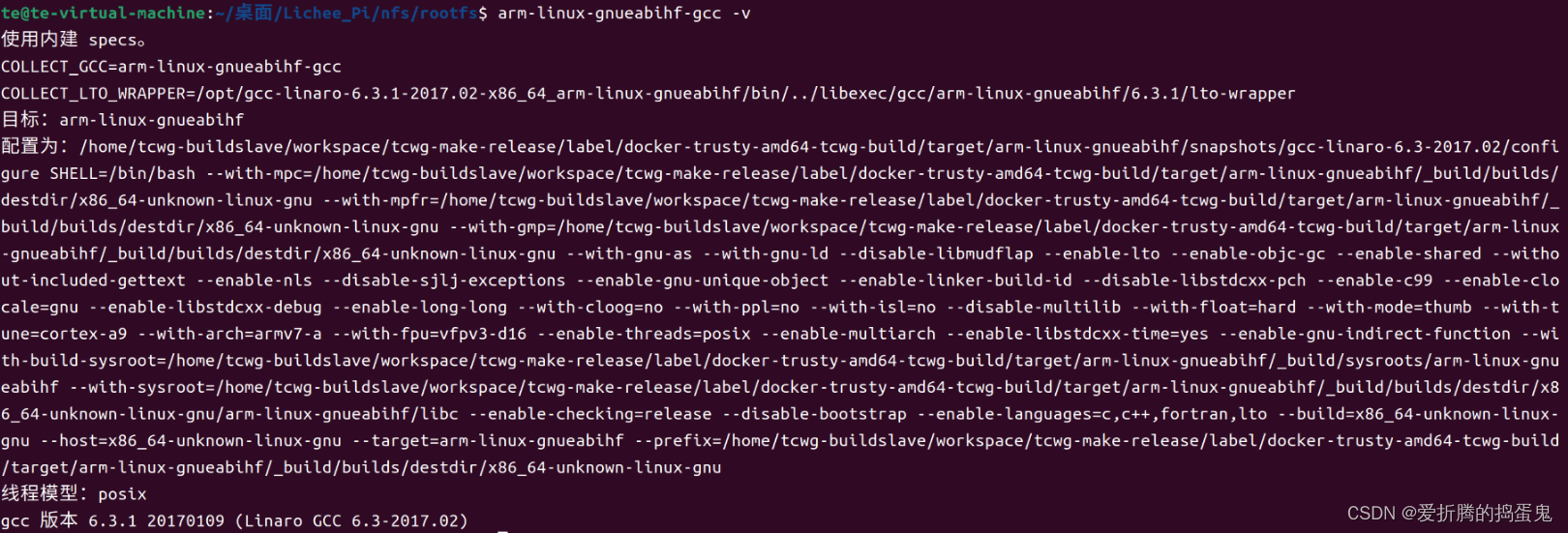
arm-linux-gnueabihf-gcc -v
结果如图所示:
d、安装设备树编译器:
sudo apt-get install device-tree-compiler
device-tree-compiler 是一个用于编译和反编译设备树(Device Tree)的工具。
2、编译U-Boot:
U-Boot的官网:U-Boot官网,从上面可以下载所有版本的U-Boot。也可以去荔枝派的网站下载V3s的U-Boot:V3s的U-Boot。
a、使用Git下载U-Boot源代码:
git clone https://github.com/Lichee-Pi/u-boot.git -b v3s-current
b、编译生成二进制文件:
cd u-boot
make ARCH=arm CROSS_COMPILE=arm-linux-gnueabihf- LicheePi_Zero_defconfig
make ARCH=arm menuconfig
make ARCH=arm CROSS_COMPILE=arm-linux-gnueabihf-
//如果需要保存编译日志则使用以下指令:
time make ARCH=arm CROSS_COMPILE=arm-linux-gnueabihf- 2>&1 | tee build.log
3、设置U-Boot从TF卡启动:
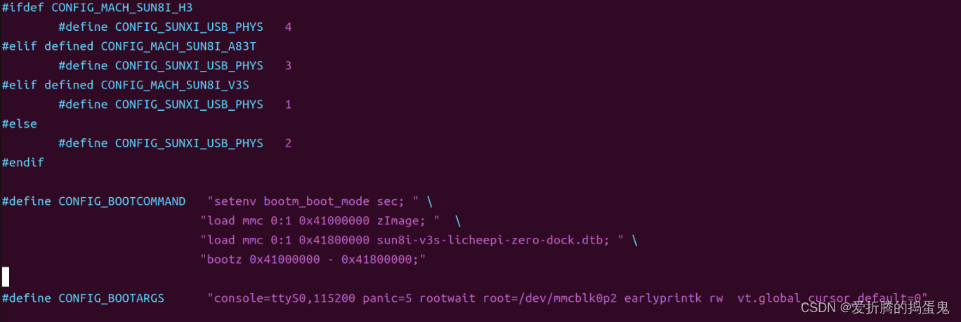
a、修改 include/configs/sun8i.h, 使u-boot可以直接从tf卡启动:
#define CONFIG_BOOTCOMMAND   "setenv bootm_boot_mode sec; " \
                            "load mmc 0:1 0x41000000 zImage; "  \
                            "load mmc 0:1 0x41800000 sun8i-v3s-licheepi-zero-dock.dtb; " \
                            "bootz 0x41000000 - 0x41800000;"

#define CONFIG_BOOTARGS      "console=ttyS0,115200 panic=5 rootwait root=/dev/mmcblk0p2 earlyprintk rw  vt.global_cursor_default=0"
b、在U-Boot中设置:
setenv bootargs 'cconsole=ttyS0,115200 panic=5 rootwait root=/dev/mmcblk0p2 earlyprintk rw  vt.global_cursor_default=0'
setenv bootcmd 'fatload mmc 0:1 0x41800000 sun8i-v3s-licheepi-zero.dtb;fatload mmc 0:1 0x41000000 zImage;bootz 0x41000000 - 0x41800000'
saveenv
4、烧录到TF卡中:
sudo dd if=u-boot-sunxi-with-spl.bin of=/dev/sdb bs=1024 seek=8
在当前目录下生成了u-boot-sunxi-with-spl.bin,将其烧录到8K偏移处启动。
5、U-Boot文件结构:
├── api                存放uboot提供的API接口函数
├── arch               平台相关的部分我们只需要关心这个目录下的ARM文件夹
│   ├──arm
│   │   └──cpu
│   │   │   └──armv7
│   │   └──dts
│   │   │   └──*.dts   存放设备的dts,也就是设备配置相关的引脚信息
├── board              对于不同的平台的开发板对应的代码
├── cmd                顾名思义,大部分的命令的实现都在这个文件夹下面。
├── common             公共的代码
├── configs            各个板子的对应的配置文件都在里面,我们的Lichee配置也在里面
├── disk               对磁盘的一些操作都在这个文件夹里面,例如分区等。
├── doc                参考文档,这里面有很多跟平台等相关的使用文档。
├── drivers            各式各样的驱动文件都在这里面
├── dts                一种树形结构(device tree)这个应该是uboot新的语法
├── examples           官方给出的一些样例程序
├── fs                 文件系统,uboot会用到的一些文件系统
├── include            头文件,所有的头文件都在这个文件夹下面
├── lib                一些常用的库文件在这个文件夹下面
├── Licenses           这个其实跟编译无关了,就是一些license的声明
├── net                网络相关的,需要用的小型网络协议栈
├── post               上电自检程序
├── scripts            编译脚本和Makefile文件
├── spl                second program loader,即相当于二级uboot启动。
├── test               小型的单元测试程序。
└── tools              里面有很多uboot常用的工具。
6、U-Boot配置:
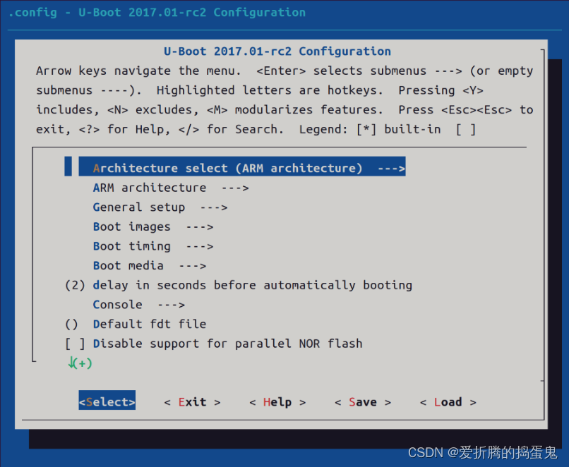
a、U-Boot配置:
make ARCH=arm menuconfig
b、Architecture select架构选择:
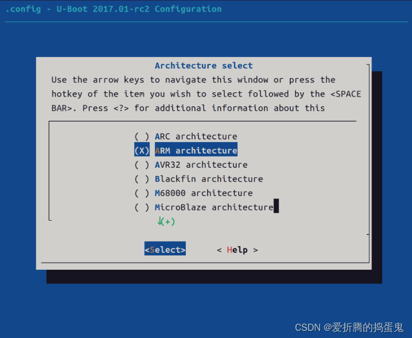
c、ARM architecture:
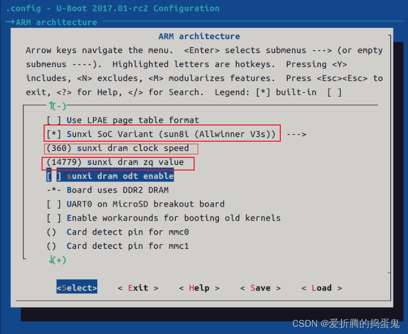
d、LCD配置:
[*] Enable graphical uboot console on HDMI, LCD or VGA   这个就是在显示设备上使能串口控制
[ ] VGA via LCD controller support   使能支持VGA通过LCD的控制器,就是LCD和VAG转换需要的控制器
(x:800,y:480,depth:18,pclk_khz:33000,le:87,ri:40,up:31,lo:13,hs:1,vs:1,sync:3,vmode:0) LCD pane
> 该选项就是配置LCD的分辨率的配置选项可以看到x是800 y是480 等等一些关于LCD的配置内容,点击回车进去可以对其进行修改。
(1)   LCD panel display clock phase   这个是LCD的显示时钟相位
()    LCD panel power enable pin      LCD的电源使能引脚
()    LCD panel reset pin             LCD的复位引脚
(PB4) LCD panel backlight pwm pin     背光PWN引脚 这个应该是调节亮度的引脚PB4
[*]   LCD panel backlight pwm is inverted            反转PWN背光引脚
[ ]   LCD panel needs to be configured via i2c
    LCD panel support (Generic parallel interface LCD panel)  --->     这个选择支持的LCDpanel
            (X) Generic parallel interface LCD panel    这里选择支持通用的并行的LCD接口
            ( ) Generic lvds interface LCD panel        这个是LVDS接口
            ( ) MIPI 4-lane, 513Mbps LCD panel via SSD2828 bridge chip
            ( ) eDP 4-lane, 1.62G LCD panel via ANX9804 bridge chip
            ( ) Hitachi tx18d42vm LCD panel
            ( ) tl059wv5c0 LCD panel
(0) GMAC Transmit Clock Delay Chain
e、时钟频率设置:
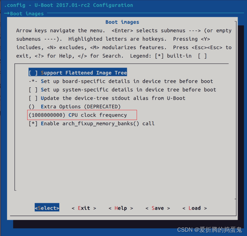
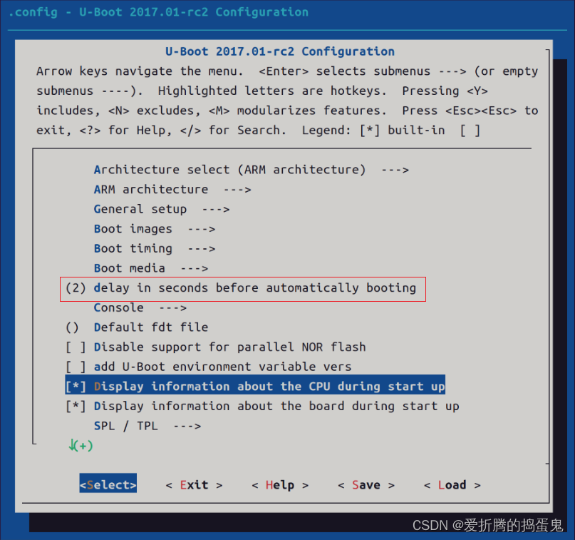
f、开机等待时间设置(以s为单位):
g、SPL设置:
SPL / TPL ---> 这个就是SPL相关的配置了
[*]   MMC raw mode: by sector                       按扇区
(0x50)  Address on the MMC to load U-Boot from  mmc加载uboot的地址
[*] Support GPIO                                 支持GPIO
[*] Support I2C                                 支持I2C
[*] Support common libraries                    支持通用lib
[*] Support disk paritions                      支持分区
[*] Support generic libraries                   支持一般lib库
[*] Support MMC                                 支持MMC
[*] Support power drivers                  支持电源驱动
[*] Support serial                               支持串口
7、U-Boot适配Ethernet:
a、配置菜单:
Device Drivers ---->
[* ]Network device suppoty ------>
[*] Allwinner Sun8i Ethernet MAC support
b、修改设备树文件:
sun8i-v3s-licheepi-zero.dts:
/dts-v1/;
#include "sun8i-v3s.dtsi"
#include "sunxi-common-regulators.dtsi"
/ {
model = "Lichee Pi Zero";
compatible = "licheepi,licheepi-zero", "allwinner,sun8i-v3s";
aliases {
/**添加以下程序**/
ethernet0 = &emac;
serial0 = &uart0;
};
chosen {
stdout-path = "serial0:115200n8";
};
};
&mmc0 {
pinctrl-0 = <&mmc0_pins_a>;
pinctrl-names = "default";
broken-cd;
bus-width = <4>;
vmmc-supply = <®_vcc3v3>;
status = "okay";
};
&uart0 {
pinctrl-0 = <&uart0_pins_a>;
pinctrl-names = "default";
status = "okay";
};
/**添加以下程序**/
&emac{
phy = <&phy0>;
phy-mode = "mii";
allwinner,use-internal-phy;
allwinner,leds-active-low;
status = "okay";
phy0: ethernet-phy@0 {
reg = <1>;
};
};
&usb_otg {
dr_mode = "otg";
status = "okay";
};
&usbphy {
usb0_id_det-gpio = <&pio 5 6 GPIO_ACTIVE_HIGH>;
status = "okay";
};
sun8i-v3s.dtsi:
#include <dt-bindings/clock/sun8i-v3s-ccu.h>
#include <dt-bindings/reset/sun8i-v3s-ccu.h>
#include <dt-bindings/interrupt-controller/arm-gic.h>
#include <dt-bindings/pinctrl/sun4i-a10.h>

/ {
	#address-cells = <1>;
	#size-cells = <1>;
	interrupt-parent = <&gic>;

	cpus {
		#address-cells = <1>;
		#size-cells = <0>;

		cpu@0 {
			compatible = "arm,cortex-a7";
			device_type = "cpu";
			reg = <0>;
			clocks = <&ccu CLK_CPU>;
		};
	};

	timer {
		compatible = "arm,armv7-timer";
		interrupts = <GIC_PPI 13 (GIC_CPU_MASK_SIMPLE(4) | IRQ_TYPE_LEVEL_LOW)>,
			     <GIC_PPI 14 (GIC_CPU_MASK_SIMPLE(4) | IRQ_TYPE_LEVEL_LOW)>,
			     <GIC_PPI 11 (GIC_CPU_MASK_SIMPLE(4) | IRQ_TYPE_LEVEL_LOW)>,
			     <GIC_PPI 10 (GIC_CPU_MASK_SIMPLE(4) | IRQ_TYPE_LEVEL_LOW)>;
	};

	clocks {
		#address-cells = <1>;
		#size-cells = <1>;
		ranges;

		osc24M: osc24M_clk {
			#clock-cells = <0>;
			compatible = "fixed-clock";
			clock-frequency = <24000000>;
			clock-output-names = "osc24M";
		};

		osc32k: osc32k_clk {
			#clock-cells = <0>;
			compatible = "fixed-clock";
			clock-frequency = <32768>;
			clock-output-names = "osc32k";
		};
	};

	soc {
		compatible = "simple-bus";
		#address-cells = <1>;
		#size-cells = <1>;
		ranges;
		/**添加以下程序**/
		syscon: syscon@01c00000 {
                       compatible = "allwinner,sun8i-h3-syscon","syscon";
                       reg = <0x01c00000 0x34>;
               };

		mmc0: mmc@01c0f000 {
			compatible = "allwinner,sun7i-a20-mmc";
			reg = <0x01c0f000 0x1000>;
			clocks = <&ccu CLK_BUS_MMC0>,
				 <&ccu CLK_MMC0>,
				 <&ccu CLK_MMC0_OUTPUT>,
				 <&ccu CLK_MMC0_SAMPLE>;
			clock-names = "ahb",
				      "mmc",
				      "output",
				      "sample";
			resets = <&ccu RST_BUS_MMC0>;
			reset-names = "ahb";
			interrupts = <GIC_SPI 60 IRQ_TYPE_LEVEL_HIGH>;
			status = "disabled";
			#address-cells = <1>;
			#size-cells = <0>;
		};

		mmc1: mmc@01c10000 {
			compatible = "allwinner,sun7i-a20-mmc";
			reg = <0x01c10000 0x1000>;
			clocks = <&ccu CLK_BUS_MMC1>,
				 <&ccu CLK_MMC1>,
				 <&ccu CLK_MMC1_OUTPUT>,
				 <&ccu CLK_MMC1_SAMPLE>;
			clock-names = "ahb",
				      "mmc",
				      "output",
				      "sample";
			resets = <&ccu RST_BUS_MMC1>;
			reset-names = "ahb";
			interrupts = <GIC_SPI 61 IRQ_TYPE_LEVEL_HIGH>;
			status = "disabled";
			#address-cells = <1>;
			#size-cells = <0>;
		};

		mmc2: mmc@01c11000 {
			compatible = "allwinner,sun7i-a20-mmc";
			reg = <0x01c11000 0x1000>;
			clocks = <&ccu CLK_BUS_MMC2>,
				 <&ccu CLK_MMC2>,
				 <&ccu CLK_MMC2_OUTPUT>,
				 <&ccu CLK_MMC2_SAMPLE>;
			clock-names = "ahb",
				      "mmc",
				      "output",
				      "sample";
			resets = <&ccu RST_BUS_MMC2>;
			reset-names = "ahb";
			interrupts = <GIC_SPI 62 IRQ_TYPE_LEVEL_HIGH>;
			status = "disabled";
			#address-cells = <1>;
			#size-cells = <0>;
		};

		usb_otg: usb@01c19000 {
			compatible = "allwinner,sun8i-h3-musb";
			reg = <0x01c19000 0x0400>;
			clocks = <&ccu CLK_BUS_OTG>;
			resets = <&ccu RST_BUS_OTG>;
			interrupts = <GIC_SPI 71 IRQ_TYPE_LEVEL_HIGH>;
			interrupt-names = "mc";
			phys = <&usbphy 0>;
			phy-names = "usb";
			extcon = <&usbphy 0>;
			status = "disabled";
		};

		usbphy: phy@01c19400 {
			compatible = "allwinner,sun8i-v3s-usb-phy";
			reg = <0x01c19400 0x2c>,
			      <0x01c1a800 0x4>;
			reg-names = "phy_ctrl",
				    "pmu0";
			clocks = <&ccu CLK_USB_PHY0>;
			clock-names = "usb0_phy";
			resets = <&ccu RST_USB_PHY0>;
			reset-names = "usb0_reset";
			status = "disabled";
			#phy-cells = <1>;
		};

		ccu: clock@01c20000 {
			compatible = "allwinner,sun8i-v3s-ccu";
			reg = <0x01c20000 0x400>;
			clocks = <&osc24M>, <&osc32k>;
			clock-names = "hosc", "losc";
			#clock-cells = <1>;
			#reset-cells = <1>;
		};

		rtc: rtc@01c20400 {
			compatible = "allwinner,sun6i-a31-rtc";
			reg = <0x01c20400 0x54>;
			interrupts = <GIC_SPI 40 IRQ_TYPE_LEVEL_HIGH>,
				     <GIC_SPI 41 IRQ_TYPE_LEVEL_HIGH>;
		};

		pio: pinctrl@01c20800 {
			compatible = "allwinner,sun8i-v3s-pinctrl";
			reg = <0x01c20800 0x400>;
			interrupts = <GIC_SPI 15 IRQ_TYPE_LEVEL_HIGH>,
				     <GIC_SPI 17 IRQ_TYPE_LEVEL_HIGH>;
			clocks = <&ccu CLK_BUS_PIO>, <&osc24M>, <&osc32k>;
			clock-names = "apb", "hosc", "losc";
			gpio-controller;
			#gpio-cells = <3>;
			interrupt-controller;
			#interrupt-cells = <3>;

			/**添加以下程序**/
			emac_rgmii_pins: emac0@0 {
                allwinner,pins = "PD0", "PD1", "PD2", "PD3",
                                "PD4", "PD5", "PD7",
                                "PD8", "PD9", "PD10",
                                "PD12", "PD13", "PD15",
                                "PD16", "PD17";
                allwinner,function = "emac";
                allwinner,drive = <SUN4I_PINCTRL_40_MA>;
                allwinner,pull = <SUN4I_PINCTRL_NO_PULL>;
            };

			uart0_pins_a: uart0@0 {
				pins = "PB8", "PB9";
				function = "uart0";
				bias-pull-up;
			};

			mmc0_pins_a: mmc0@0 {
				pins = "PF0", "PF1", "PF2", "PF3",
				       "PF4", "PF5";
				function = "mmc0";
				drive-strength = <30>;
				bias-pull-up;
			};
		};

		timer@01c20c00 {
			compatible = "allwinner,sun4i-a10-timer";
			reg = <0x01c20c00 0xa0>;
			interrupts = <GIC_SPI 18 IRQ_TYPE_LEVEL_HIGH>,
				     <GIC_SPI 19 IRQ_TYPE_LEVEL_HIGH>;
			clocks = <&osc24M>;
		};

		wdt0: watchdog@01c20ca0 {
			compatible = "allwinner,sun6i-a31-wdt";
			reg = <0x01c20ca0 0x20>;
			interrupts = <GIC_SPI 25 IRQ_TYPE_LEVEL_HIGH>;
		};

		uart0: serial@01c28000 {
			compatible = "snps,dw-apb-uart";
			reg = <0x01c28000 0x400>;
			interrupts = <GIC_SPI 0 IRQ_TYPE_LEVEL_HIGH>;
			reg-shift = <2>;
			reg-io-width = <4>;
			clocks = <&ccu CLK_BUS_UART0>;
			resets = <&ccu RST_BUS_UART0>;
			status = "disabled";
		};

		uart1: serial@01c28400 {
			compatible = "snps,dw-apb-uart";
			reg = <0x01c28400 0x400>;
			interrupts = <GIC_SPI 1 IRQ_TYPE_LEVEL_HIGH>;
			reg-shift = <2>;
			reg-io-width = <4>;
			clocks = <&ccu CLK_BUS_UART1>;
			resets = <&ccu RST_BUS_UART1>;
			status = "disabled";
		};

		uart2: serial@01c28800 {
			compatible = "snps,dw-apb-uart";
			reg = <0x01c28800 0x400>;
			interrupts = <GIC_SPI 2 IRQ_TYPE_LEVEL_HIGH>;
			reg-shift = <2>;
			reg-io-width = <4>;
			clocks = <&ccu CLK_BUS_UART2>;
			resets = <&ccu RST_BUS_UART2>;
			status = "disabled";
		};

		/**添加以下程序**/
		emac: ethernet@1c30000 {
            compatible = "allwinner,sun8i-h3-emac";
            reg = <0x01c30000 0x104>, <0x01c00030 0x4>;
            reg-names = "emac", "syscon";
            interrupts = <GIC_SPI 82 IRQ_TYPE_LEVEL_HIGH>;
            resets = <&ccu RST_BUS_EMAC>, <&ccu RST_BUS_EPHY>;
            reset-names = "ahb", "ephy";
            clocks = <&ccu CLK_BUS_EMAC>, <&ccu CLK_BUS_EPHY>;
            clock-names = "ahb", "ephy";
            #address-cells = <1>;
            #size-cells = <0>;
            status = "disabled";
        };


		gic: interrupt-controller@01c81000 {
			compatible = "arm,cortex-a7-gic", "arm,cortex-a15-gic";
			reg = <0x01c81000 0x1000>,
			      <0x01c82000 0x1000>,
			      <0x01c84000 0x2000>,
			      <0x01c86000 0x2000>;
			interrupt-controller;
			#interrupt-cells = <3>;
			interrupts = <GIC_PPI 9 (GIC_CPU_MASK_SIMPLE(4) | IRQ_TYPE_LEVEL_HIGH)>;
		};
	};
};
编译之后出现以下,则代表网卡可以使用:

c、设置网络:
setenv ipaddr 192.168.1.50				//开发板 ip 地址,可以不设置,使用 dhcp 命令来从路由器获取 IP 地址。
setenv ethaddr b8:ae:1d:01:00:00		//开发板的 MAC 地址,一定要设置。
setenv gatewayip 192.168.1.1			//网关地址。
setenv netmask 255.255.255.0			//子网掩码。
setenv serverip 192.168.1.4				//服务器 IP 地址,也就是 Ubuntu 主机 IP 地址,用于调试代码。
saveenv
8、小问题:
当出现以下情况,则说明网络正常:

当出现以下情况,则说明网络异常:

出现异常的原因之一是,当时使用的虚拟机,没有将网络设置为桥接模式,但是板子连接的是外部的路由器,由于网关不通,造成的网络不通,将虚拟机改成桥接模式之后,再进行ping,即可联通。


