1 官方资料
NXP官方提供了MCUBoot SDK:NXP_Kinetis_Bootloader_2.0.0 package,里面包含了各种型号芯片的的BootLoader。
- BootLoader参考手册:
doc/Kinetis Bootloader v2.0.0 Reference Manual.pdf - 上位机程序参考手册:
Kinetis Flash Tool User's Guide.pdf
2 BootLoader流程分析
根据自己的芯片型号打开Targets文件夹下的IAR或Keil工程。
2.1 bootloader_config.h和bl_context.c
SDK支持多个外设进行更新,又支持QSPI、MMCAU等功能,这些功能都可以在这个bootloader_config.h中打开和关闭。下面为SDK支持的上位机和MCU进行通信时支持的外设,一般我们也只用一个外设进行更新,看你用到的是哪个就打开哪个。以串口为例,就是在中断中获取上位机发来的数据填充到buffer中,然后供后面死循环中的pump函数解析。
#define BL_CONFIG_SCUART (1)
#define BL_CONFIG_I2C (1)
#define BL_CONFIG_DSPI (1)
#define BL_CONFIG_USB_HID (1)
#define BL_CONFIG_USB_MSC (1)
还有一个文件bl_context.c,里面有各个接口的控制结构体和内存映射数组。其它文件都是通过g_bootloaderContext 这个变量调用具体的接口。
bootloader_context_t g_bootloaderContext = {.memoryInterface = &g_memoryInterface,
                                            .memoryMap = g_memoryMap,
                                            .allPeripherals = g_peripherals,
                                            .activePeripheral = NULL, // Filled in at run time.
                                            .propertyInterface = &g_propertyInterface,
                                            .commandInterface = &g_commandInterface,
                                            .flashDriverInterface = &g_flashDriverInterface,
#if AES_SECURITY_SUPPORTED
                                            .aesInterface = &g_aesInterface
#endif
};
2.2 bl_main.c
首先,当然是从main函数开始进行分析。main函数在bl_main.c中,分别执行了bootloader_init()和bootloader_run()函数。
int main(void)
{
    bootloader_init();
    bootloader_run();

    // Should never end up here.
    debug_printf("Warning: reached end of main()\r\n");
    return 0;
}
2.2.1 bootloader_init
函数具体完成的功能都写在注释中。
static void bootloader_init(void)
{
    // 在fsl_rtos_abstraction.c中实现了信号量机制,初始化信号量
    lock_init();

    // 使能各个Port引脚
    init_hardware();

    // 初始化Flash驱动:调用fsl_flash.c中的接口
    bootloader_flash_init();

    // 从(APP偏移地址+配置结构体偏移地址)处取出配置结构体
    g_bootloaderContext.propertyInterface->load_user_config();

    // 使用QSPI Flash的话需要初始化,这里不使用
#if BL_FEATURE_QSPI_MODULE
    configure_quadspi_as_needed();
#endif // BL_FEATURE_QSPI_MODULE

    // 配置系统时钟,会根据前面取出来的配置结构体中的相关时钟参数进行配置
    configure_clocks(kClockOption_EnterBootloader);

    // 使能计数器,实际上是使用Systick计数
    microseconds_init();

	// 使能看门口,这里我没打开
#if BL_FEATURE_BYPASS_WATCHDOG
    g_bootloaderContext.flashDriverInterface->flash_register_callback(&g_bootloaderContext.flashState,
                                                                      bootloader_watchdog_service);
    bootloader_watchdog_init();
#endif // BL_FEATURE_BYPASS_WATCHDOG

    // 初始化SRAM,保存Flash和SRAM的部分信息
    g_bootloaderContext.memoryInterface->init();

    // 将Flash和SRAM的相关信息保存在g_bootloaderContext.propertyInterface->store中
    g_bootloaderContext.propertyInterface->init();

	// 可靠更新:实际上是将Flash分为两块,先读取到后面,校验后再写到前面,这里不打开
#if BL_FEATURE_RELIABLE_UPDATE
    bootloader_reliable_update_as_requested(kReliableUpdateOption_Normal, 0);
#endif // BL_FEATURE_RELIABLE_UPDATE

    // 从刚刚支持的外设中获取使能的外设并初始化,如果没找到就直接进入应用程序
    // 串口就是初始化引脚,该SDK还有自动检测波特率功能,初始化相关代码
    g_bootloaderContext.activePeripheral = get_active_peripheral();

    // 该函数一般不需要实现,留空即可
    if (g_bootloaderContext.activePeripheral->byteInterface &&
        g_bootloaderContext.activePeripheral->byteInterface->init)
    {
        g_bootloaderContext.activePeripheral->byteInterface->init(g_bootloaderContext.activePeripheral);
    }
	// 对于串口来说,packetInterface的初始化没有代码
    if (g_bootloaderContext.activePeripheral->packetInterface &&
        g_bootloaderContext.activePeripheral->packetInterface->init)
    {
        g_bootloaderContext.activePeripheral->packetInterface->init(g_bootloaderContext.activePeripheral);
    }

    // 初始化与上位机交互的command模块
    g_bootloaderContext.commandInterface->init();
}
2.2.2 bootloader_run
可以看到bootloader_run中的代码很简单,就是进入一个死循环,调用commandInterface->pump()函数来解析上位机发来的命令和数据。实际上就是调用command.c中的bootloader_command_pump()函数进入死循环,不断获取activePeripheral的接收到的数据,这个数据按照一定的协议进行传输,先发command再发data。具体上位机与MCU通信协议的格式参考doc/Kinetis Bootloader v2.0.0 Reference Manual.pdf中的Chapter 4:BootLoader packet types。
static void bootloader_run(void)
{
    const peripheral_descriptor_t *activePeripheral = g_bootloaderContext.activePeripheral;
    while (1)
    {
        g_bootloaderContext.commandInterface->pump();
        // 调用activePeripherral的pump函数,该函数一般不需要实现,留空即可
        if (activePeripheral->controlInterface->pump)
        {
            activePeripheral->controlInterface->pump(activePeripheral);
        }
    }
}
3 上位机分析
可以发现,上面的代码流程并不复杂,最后就进入了命令解析函数中,等待上位机发来的命令,那么对于程序更新,上位机会发来什么命令呢?
- 参考上位机KinetisFlashTool源码:
\NXP_Kinetis_Bootloader_2_0_0\apps\KinetisFlashTool\KinetisFlashTool.sln - 该工程为MFC工程,需要使用Visual Studio打开。
打开Bootloader.cpp文件,在按下软件中的更新按钮后会触发以下代码:
UINT ThreadFunc(LPVOID pParam)
{
	......
	case WAIT_OBJECT_0 + 4: // Update Image
		PrintLog(_T("Start update progress......"));
		pBootloader->progressCallback(0, 1, 1); // Reset the progress bar
#ifndef DISABLE_QUICK_UPDATE
		// If not connect to a device, try to connect firstly.
		if ((!pBootloader->m_isConneted) || (pBootloader->m_updater == NULL))
		{
			bool cntStatus = false;
			PrintLog(_T("No device is connected!\r\nTry to connect device......"));
			// Try 5 attempts to connect device.
			for (size_t retry = 0; retry < 5; retry++)
			{
				try
				{
					// If it is not NULL, delete it,  for the reason that peripheral
					// configuration might be changed.
					if (pBootloader->m_updater != NULL)
						delete pBootloader->m_updater;

					pBootloader->m_updater = new blfwkdll::Updater(&pBootloader->m_config);

					PrintLog(_T("Connected to device successfully!"));
					// Connect opertion is sucessful.
					cntStatus = true;
					break;
				}
				catch (const std::exception &e)
				{
					PrintLog(_T("Error: Connect device failed(%s) at %d attempts."), CString(e.what()),
							 retry + 1);
					Sleep(500); // Wait 500ms.
				}
			}
			if (cntStatus)
			{
				try
				{
					pBootloader->m_updater->getProperty(
						blfwkdll::Updater::PROPERTY_TAG::kPropertyTag_FlashSecurityState, responseWords);
					pBootloader->m_targetInfo.securityState = responseWords[1];
					PrintLog(_T("Get device security state successfully(%s)."),
							 responseWords[1] ? _T("SECURE") : _T("UNSECURE"));
				}
				catch (const std::exception &e)
				{
					PrintLog(_T("Error: Get device security state failed(%s)."), CString(e.what()));
					goto UpdateError;
				}
			}
			else
			{
				PrintLog(_T("Error: Try to connect device failed."));
				goto UpdateError;
			}
		}
#else
		if (pBootloader->m_updater == NULL)
		{
#ifdef _DEBUG
			PrintLog(_T("Error: Invalid Bootloader.m_updater(NULL).\r\n"));
#else
			PrintLog(_T("Error: Fail to communicate with device. Please reconnet the device.\r\n"));
#endif
			break;
		}
#endif
		pBootloader->m_updater->registerCallback(pBootloader->progressCallback, &(pBootloader->m_abort));

		if (pBootloader->m_targetInfo.securityState)
		{
			try
			{
				if (pBootloader->m_firmwareConfig.doErasetoUnlock)
				{
					PrintLog(_T("Unlock device by ERASEALL......"));
					pBootloader->m_updater->eraseAllUnsecure();
					PrintLog(_T("Device is unlocked!"));
				}
				else if (pBootloader->m_firmwareConfig.useKeytoUnlock)
				{
					PrintLog(_T("Unlock device by BACKDOORKEY......"));

					pBootloader->m_updater->unlockWithKey(pBootloader->m_firmwareConfig.backdoorkey);
					PrintLog(_T("Device is unlocked!"));
				}
				else
				{
					PrintLog(_T("Update directly without unlock device."));
				}
			}
			catch (const std::exception &e)
			{
				PrintLog(_T("Error: Unlock device failed(%s)."), CString(e.what()));
				goto UpdateError;
			}
		}

		try
		{
			PrintLog(_T("Updating image......"));
			status = pBootloader->m_updater->flashFirmware(&pBootloader->m_firmwareConfig.imageFilePath,
														   pBootloader->m_firmwareConfig.baseAddress);
			PrintLog(_T("Update image successfully!"));
			if (status == Bootloader::KibbleStatusCode::KBL_Status_Success)
			{
				pBootloader->m_updater->reset();
				PrintLog(_T("Reset device successfully!"));
			}
			else if (status = Bootloader::KibbleStatusCode::KBL_Status_AbortDataPhase)
			{
				pBootloader->progressCallback(100, 1, 1);
			}
			// for the left cases, an exception will be throw out.
		}
		catch (const std::exception &e)
		{
			PrintLog(_T("Error: Update image failed(%s)."), CString(e.what()));
			goto UpdateError;
		}
		PrintLog(_T("Update process is completed.\r\n"));

		delete pBootloader->m_updater;
		pBootloader->m_updater = NULL;

		// Status is changed from connected to disconnected, send out the message.
		if (pBootloader->m_isConneted)
		{
			pBootloader->m_isConneted = false;
			::PostMessage(*g_pMainDlg, USER_MS_CONNECTION_CHANGE, NULL, NULL);
		}
		break;

	UpdateError:
		PrintLog(_T("Update process is stopped by error.\r\n"));
		break;
}
上面的代码就是根据指定的协议调用BootLoader中相关的命令,这些命令会被Bootloader中的pump函数解析。大概流程就是连接MCU的外设,用作与MCU的通信。连接成功后,首先获取Flash的加密状态,如果加密的话需要进行解密。接下来就是调用flashFirmware函数,大概流程如下:
flashFirmware
	flashFromSourceFile
		/* 写入程序之前需要先擦除对应扇区的数据 */
		eraseFlashRegion(segment->getBaseAddress(), segment->getLength());
		/* 写入Flash */
		writeMemory(segment);
eraseFlashRegion对应BootLoader中的mem_erase函数writeMemory对应BootLoader中的mem_write函数
程序中将待写入Flash的程序分为了多个segment,通过约定好的协议进行传输,以writeMemory为例,协议示例如下:
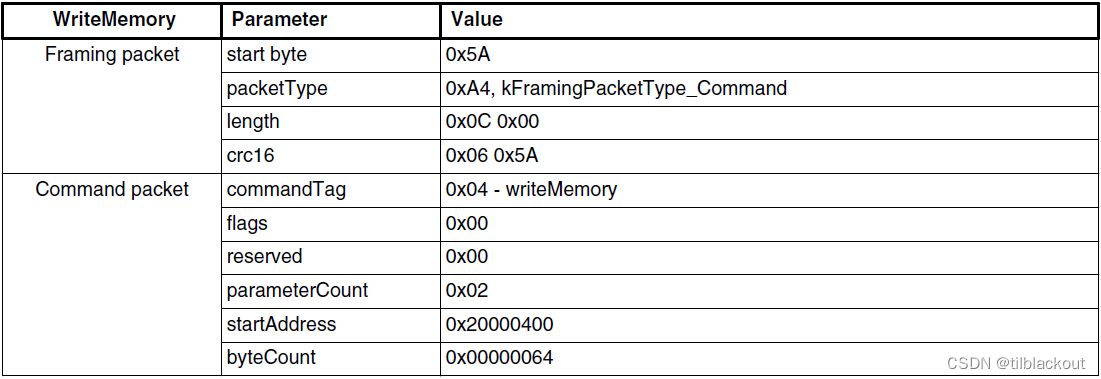
BootLoader在接收到这个命令后,如果参数和CRC也正确,pump就从kCommandState_CommandPhase状态进入kCommandState_DataPhase状态,来接收byteCount个数据。也就是在烧写程序时,上位机将程序分为多个Segment,每次发byteCount个数据,只有当CRC正确的时候再写入Flash中。
4 编写自己SD卡的BootLoader
4.1 精简代码
官方给的BootLoader毕竟是为了兼容多个外设和Flash,又要支持一些可选功能。对于我来说,不希望BootLoader中有无关的代码,所以我会仅留下自己需要用的代码。这里我希望实现一个最精简的BootLoader,不用校验,不用其它与上位机通信等功能。
1、首先是删除掉不需要使用的外设,SDK中支持UART、I2C等外设,用不到,相关文件和宏定义全部删除
2、接着是删除掉一些不用的功能所对应的文件,如MMCAU、QSPI和OTFAD、Reliable Update等文件
3、将g_bootloaderContext中的各个interface的定义全部删除,直接应用到我们后续将写的更新代码中,比如对于allPeripherals和activePeripheral,我们就只用一个peripheral,所以这些变量全都删除,同时也要在bl_main.c中删除相关代码。其它的,比如commandInterface,我们不用与上位机通信,删除bl_command.c文件;比如flashDriverInterface,我们仅仅使用了mem_erase和mem_write函数,直接在使用的地方调用就行。
- 删除这些文件和定义再去编译工程一般都会出现一些错误,一般都是更改了一个地方就去解决一下编译错误。
4、BootLoader会读取程序0xA3C0(APP首地址+配置偏移)处开始的一段内存,其中0xA000~0xA3C0处为中断向量表,中间空的一大段都用DefaultISR填充,以保证0x3C0偏移处为这个配置项,这个配置项叫做BCA(BootLoader Configuration Area),SDK中定义如下:
typedef struct BootloaderConfigurationData
{
    uint32_t tag; //!< [00:03] Tag value used to validate the bootloader configuration data. Must be set to 'kcfg'.
    uint32_t crcStartAddress;              //!< [04:07]
    uint32_t crcByteCount;                 //!< [08:0b]
    uint32_t crcExpectedValue;             //!< [0c:0f]
    uint8_t enabledPeripherals;            //!< [10:10]
    uint8_t i2cSlaveAddress;               //!< [11:11]
    uint16_t peripheralDetectionTimeoutMs; //!< [12:13] Timeout in milliseconds for peripheral detection before jumping
    //! to application code
    uint16_t usbVid;                    //!< [14:15]
    uint16_t usbPid;                    //!< [16:17]
    uint32_t usbStringsPointer;         //!< [18:1b]
    uint8_t clockFlags;                 //!< [1c:1c] High Speed and other clock options
    uint8_t clockDivider;               //!< [1d:1d] One's complement of clock divider, zero divider is divide by 1
    uint8_t bootFlags;                  //!< [1e:1e] One's complemnt of direct boot flag, 0xFE represents direct boot
    uint8_t pad0;                       //!< [1f:1f] Reserved, set to 0xFF
    uint32_t mmcauConfigPointer;        //!< [20:23] Holds a pointer value to the MMCAU configuration
    uint32_t keyBlobPointer;            //!< [24:27] Holds a pointer value to the key blob array used to configure OTFAD
    uint8_t pad1;                       //!< [28:28] reserved
    uint8_t canConfig1;                 //!< [29:29] ClkSel[1], PropSeg[3], SpeedIndex[4]
    uint16_t canConfig2;                //!< [2a:2b] Pdiv[8], Pseg1[3], Pseg2[3],  rjw[2]
    uint16_t canTxId;                   //!< [2c:2d] txId
    uint16_t canRxId;                   //!< [2e:2f] rxId
    uint32_t qspi_config_block_pointer; //!< [30:33] QSPI config block pointer.
} bootloader_configuration_data_t;
这个配置结构体把所有外设需要配置的功能都写上去了,对于clockFlags和clockDivider来说,主要是为了在使用USB的情况下,配置更高频率的时钟;对于tag来说,它是一个标识符,在BootLoader中读取出来如果不是kcfg的话表示出错;还有CRC校验功能,主要是在reliable update文件中使用;对于bootFlags来说,如果为1就进入后续判断,不与上位机连接,直接进入用户程序。
很明显,这些参数基本上我们都用不到,对于时钟来说不用USB直接选择21MHz时钟即可,这里实现一个最简单的BootLoader,也不用CRC功能。所以修改结构体bootloader_configuration_data_t的定义,这里修改了,同时还需要在后面我们写的APP程序中的汇编启动.S文件中声明和定义这个结构体。由于用不到这里的数据,将BootLoader中这个结构体和读取这段数据的代码去掉,将APP中也不声明这段内存。
最终工程的大小从30多KB,缩小到了8KB。
4.2 编写SD卡更新驱动
由前面分析可知,上位机无非就是通过约定好的协议将程序分为多个segment,然后每个segment加上校验,写入Flash中。然后在写Flash之前要判断Flash是否加密,若加密则需要解密,然后在写Flash之前还需要先将待写区域擦除为0xFF。这里我们不用这个协议,直接从SD卡中读取然后写入。所以流程非常的清晰,我们只需要从SD卡中获取程序的bin文件,按照上面的流程走就行了。
首先当然是移植SD卡驱动和fatfs文件系统,NXP有提供相关驱动,这里不做过多介绍。其中有FreeRTOS版的也有裸机版的驱动,这里应该选裸机版的。移植的过程中需要修改一下时钟的宏定义为你配置的时钟周期,部分函数会与fsl_rtos_abstraction.c中命名冲突,但实际上那些函数都没使用,删掉就好了。
BootLoader代码的大致流程如下:
f_open(&updateFile, UPDATE_PATH, FA_READ) ;
/* 检查Flash是否加密 */
FLASH_GetSecurityState(&g_bootloaderContext.flashState, &flashState);
if(flashState != kFLASH_SecurityStateNotSecure)
	flash_mem_erase_all_unsecure();
BaseAddr = BL_APP_VECTOR_TABLE_ADDRESS;
/* erase待写区域 */
/* fileSize需要向上对齐为Flash的一个Sector的大小 */
mem_erase(BaseAddr, fileSize);
/* 写入Flash */
BaseAddr = BL_APP_VECTOR_TABLE_ADDRESS;
dataCnt = 0;
while(1)
{
	memset(read_buf, 0xff, sizeof(read_buf));
	f_read(&updateFile, read_buf, READ_EVERY_STEP, &br) ;
	mem_write(BaseAddr, br, read_buf) ;
	if(feof(&updateFile))
	{
		mem_flush();
		break;
	}
}
- 对于APP来说,需要修改分散文件(我用的是IAR),在工程的icf文件中,将用户程序的起始地址
__ICFEDIT_intvec_start__定义为0x0000A000。 - 若生成的BootLoader bin文件大小大于40KB,则要增大这个大小。在我工作中写的BootLoader中加了fatfs、reliable update和MMCAU等功能,去除掉所有无关代码,生成的bin文件大小为29KB,所以40KB完全够了,没加文件系统的话15KB差不多。
本篇文章主要是理解NXP BootLoader源码,精简文件目的也是理解其中的过程,实际工程中肯定还需要在BCA处添加CRC校验的信息对整个文件进行CRC校验,SDK中给的BCA确实太多没用的东西了,但是这些CRC校验起始地址、大小和校验和都需要在编译完bin文件之后用KinetisFlashTool将这些项目填进去,所以如果修改了这个BCA处结构的内容,就不能用这个软件填写了,大家可以自己写一个程序来打开bin文件fseek到0x3c0处的区域进行填写,CRC校验函数在SDK中有软件实现的代码,我已经写过一个QT程序来计算和填写CRC字段和MMCAU AES加密字段,完全没有问题。

![[附源码]java毕业设计咖啡销售管理系统-](https://img-blog.csdnimg.cn/8a415ff63ffb4f6cb33997f86a72fe4d.png)








![[R]第二节 练习一关于数值向量](https://img-blog.csdnimg.cn/img_convert/45df159894ce91e4d676bf728793d9d9.png)
