一、I2C简介
I2C老朋友了,在单片机里面也学过,现在再复习一下。I2C使用两条线在主控制器和从机之间进行数据通信。一条是 SCL(串行时钟线),另外一条是 SDA(串行数据线),这两条数据线需要接上拉电阻,总线空闲的时候 SCL 和 SDA 处于高电平。
I2C 是支持多从机的,也就是一个 I2C 控制器下可以挂多个 I2C 从设备,这些不同的 I2C从设备有不同的器件地址,这样 I2C 主控制器就可以通过 I2C 设备的器件地址访问指定的 I2C设备了,如下图:
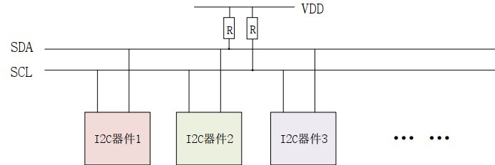
SDA 和 SCL 都必须接一个上拉电阻,一般是 4.7K。其余的 I2C 从器件都挂接到 SDA 和 SCL 这两根线上,这样就可以通过 SDA 和 SCL 这两根线来访问多个 I2C 设备。
1. 起始位
I2C 通信起始标志,通过起始位可以告诉 I2C 从机,主机要进行 I2C 通信。在 SCL 为高电平的时候,SDA 为下降沿的时候是起始位。

2. 停止位
停止位就是 I2C 停止通信的标志位,和起始位功能相反。在 SCL 为高电平的时候,SDA 出现上升沿就表示停止位。

3. 数据传输
I2C 总线进行数据传输的时候,要保证在 SCL 高电平期间,SDA 上的数据稳定,所以只有当SCL 为低电平的时候,SDA 才能进行数据变化。

4. 应答信号
当 I2C 主机发送完 8 位数据之后会将 SDA 设置为输入状态,等待从机应答(等待从机告诉主主机接收到了数据)。应答信号是从从机发送,主机只需要提供应答信号所需要的时钟。其实主机发送完数据之后的一个时钟信号就是给应答信号使用的。从机将 SDA 拉低表示发出应答信号,也就是通信成功,否则通信失败。
5. I2C 写时序
主机和从机通信就两个操作:读和写。

MSB:数据最高有效位。
1:开始信号,就是起始位。
2:发送 I2C 设备地址,每一个 I2C 器件都有一个设备地址,通过具体的设备地址就可以访问设备,其中高 7 位是设备地址,最后一位是读写位。为 1 表示读操作,为 0 表示写操作。
3:I2C 设备地址后面跟着一位读写位,1表示读操作,0表示写操作。
4:从机发送的 ACK 应答信号。
5:从新开始发送信号。
6:发送要写入数据的寄存器地址。
7:从机发送 ACK 应答信号。
8:发送给寄存器的数据。
9:从机发送 ACK 应答信号。
10:停止信号。
6. I2C 读时序

I2C 读时序总共 4 步:第一步发送设备地址;第二步发送读取的寄存器地址;第三步重新发送设备地址;第四步是 I2C 从设备输出要读取的寄存器值。
1:主机发送起始位;
2:主机发送要读取的从设备地址;
3:读取控制位,向从机发送数据,这里是写信号。
4:从机发送 ACK 应答信号;
5:重新发送起始位;
6:主机发送要读取的寄存器地址;
7:从机发送 ACK 应答信号;
8:重新发送起始位;
9:重新发送要读取的从设备地址;
10:读写控制位,这里是读信号,接下来是从设备里面读取数据;
11:从机发送 ACK 应答信号;
12:主机从从机那读取的数据;
13:主机发送 NO ACK 信号表示读取完成,不需要从机发送 ACK 信号。
14:主机发送 STOP 信号,停止位。
二、AP3216C 简介
STM32MP1 开发板上通过 I2C5 连接了一个三合一环境传感器: AP3216C。支持环境光强度(ALS)、接近距离(PS)和红外线强度(IR)这三个环境参数检测。该芯片可以通过 IIC 接口与主控制相连,并且支持中断。
AP3216C 常被用于手机、平板、导航设备等,其内置的接近传感器可以用于检测是否有物
体接近,比如手机上用来检测耳朵是否接触听筒,如果检测到的话就表示正在打电话,手机就
会关闭手机屏幕以省电。也可以使用环境光传感器检测光照强度,可以实现自动背光亮度调节。
AP3216 的设备地址为 0X1E,通过这些寄存器我们可以配置 AP3216C 的工作模式,并且读取相应的数据。以下是 AP3216C 寄存器。
| 寄存器地址 | 位 | 寄存器功能 | 描述 |
| 0x00 | 2:0 | 系统模式 | 000:掉电模式(默认) 001:使能ALS 010:使能PS+IR 011:使能ALS+PS+IR 100:软复位 101:ALS单次模式 110: PS+IR 单次模式。111: ALS+PS+IR 单次模式 |
| 0X0A | 7 1:0 | IR 低位数据 | 0: IR&PS 数据有效, 1:无效 IR 最低 2 位数据。 |
| 0X0B | 7:0 | IR 高位数据 | IR 高 8 位数据 |
| 0X0C | 7:0 | ALS 低位数据 | ALS 低 8 位数据 |
| 0X0D | 7:0 | ALS 高位数据 | ALS 高 8 位数据 |
| 0X0E | 7 6 3:0 | PS 低位数据 | 0,物体在远离; 1,物体在接近 0, IR&PS 数据有效; 1, IR&PS 数据无效PS 最低 4 位数据 |
| 0X0F | 7 6 5:0 | PS 高位数据 | 0,物体在远离; 1,物体在接近 0, IR&PS 数据有效; 1, IR&PS 数据无效PS 最低 6 位数据 |
0X00 这个寄存器是模式控制寄存器,用来设置 AP3216C 的工作模式,一般开始先将其设置为 0X04,也就是先软件复位一次 AP3216C。接下来根据实际使用情况选择合适的工作模式,比如设置为 0X03,也就是开启 ALS+PS+IR。 0X0A~0X0F 这 6 个寄存器就是数据寄存器,保存着 ALS、 PS 和 IR 这三个传感器获取到的数据值。如果同时打开 ALS、 PS 和 IR 的读取间隔最少要 112.5ms,因为 AP3216C 完成一次转换需要 112.5ms。
三、Linux 中 I2C 的总线框架
使用裸机方式编写 I2C 设备的驱动程序,需要实现两个部分:
1、I2C 主机驱动;2、I2C设备驱动。
I2C 主机驱动也就是 SoC 的 I2C 控制器对应的驱动程序,I2C 设备驱动其实就是挂在
I2C 总线下的具体设备对应的驱动程序,比如 eeprom、触摸屏 IC 等等。对于主机驱动来说,只要编写完成就不需要更改,其他的 I2C 设备都是直接调用主机驱动提供的 API 函数来完成读写操作即可。
I2C 总线框架也叫 I2C 子系统,总体如下:

1、I2C核心(I2C-core)
I2C 核心提供了 I2C 总线驱动(适配器)和设备驱动的注册、注销方法, I2C 通信方法
(algorithm)与具体硬件无关的代码。
2、I2C 总线驱动(I2C_adapter)
I2C 总线驱动是 I2C 适配器的软件实现,提供 I2C 适配器与从设备间完成数据通信的能力。I2C 总线驱动由 i2c_adapter 和 i2c_algorithm 来描述。 I2C 适配器是 SoC 中内置 i2c 控制器的软
件抽象,可以理解为他所代表的是一个 I2C 主机。
3、I2C设备驱动(I2C_client_driver)
包括两部分:设备的注册和驱动的注册。
I2C 子系统帮助内核统一管理 I2C 设备,让驱动开发工程师在内核中可以更加容易地添加
自己的 I2C 设备驱动程序。
1.I2C 总线驱动
首先复习一下 platform,它是虚拟出来的一条总线,目的就是为了实现总线、设备、驱动框架。那 I2C 呢,是不需要虚拟的,直接使用 I2C 总线即可。I2C 总线驱动重点是 I2C 适配器(SOC 的 I2C 接口控制器)驱动,这里会有两个重要数据结构:i2c_adapter 和 i2c_algorithm,I2C 子系统将 SoC 的适配器抽象成一个 i2c_adapter 结构体,它在 include/linux/i2c.h 文件中:
struct i2c_adapter {
    struct module *owner;
    unsigned int class;
    const struct i2c_algorithm *algo;
    void *algo_data;

    /* data fields that are valid for all devices */
    const struct i2c_lock_operations *lock_ops;
    struct rt_mutex bus_lock;
    struct rt_mutex mux_lock;

    int timeout; /* in jiffies */
    int retries;
    struct device dev; /* the adapter device */
    unsigned long locked_flags;
    #define I2C_ALF_IS_SUSPENDED 0
    #define I2C_ALF_SUSPEND_REPORTED 1

    int nr;
    char name[48];
    struct completion dev_released;

    struct mutex userspace_clients_lock;
    struct list_head userspace_clients;

    struct i2c_bus_recovery_info *bus_recovery_info;
    const struct i2c_adapter_quirks *quirks;

    struct irq_domain *host_notify_domain;
};
i2c_algorithm 结构体定义在 include/linux/i2c.h 文件中:
struct i2c_algorithm {
    /*
     * If an adapter algorithm can't do I2C-level access, set
     * master_xfer to NULL. If an adapter algorithm can do SMBus
     * access, set smbus_xfer. If set to NULL, the SMBus protocol is
     * simulated using common I2C messages.
     *
     * master_xfer should return the number of messages successfully
     * processed, or a negative value on error.
     */
    int (*master_xfer)(struct i2c_adapter *adap, struct i2c_msg *msgs, int num);
    int (*master_xfer_atomic)(struct i2c_adapter *adap, struct i2c_msg *msgs, int num);
    int (*smbus_xfer)(struct i2c_adapter *adap, u16 addr, unsigned short flags,
                     char read_write, u8 command, int size, union i2c_smbus_data *data);
    int (*smbus_xfer_atomic)(struct i2c_adapter *adap, u16 addr, unsigned short flags,
                            char read_write, u8 command, int size, union i2c_smbus_data *data);

    /* To determine what the adapter supports */
    u32 (*functionality)(struct i2c_adapter *adap);

    #if IS_ENABLED(CONFIG_I2C_SLAVE)
    int (*reg_slave)(struct i2c_client *client);
    int (*unreg_slave)(struct i2c_client *client);
    #endif
};
master_xfer 是 I2C 适配器的传输函数,通过此函数可以完成完成与 I2C 设备之间的通信。
smbus_xfer 是 SMBUS 总线的传输函数。smbus 协议是从 I2C 协议的基础上发展而来的,他们之间有很大的相似度, SMBus 与 I2C 总线之间在时序特性上存在一些差别,应用于移动 PC 和桌面 PC 系统中的低速率通讯。
I2C 总线驱动主要工作就是初始化 i2c_adapter 结构体变量,然后设置 i2c_algorithm 中的 master_xfer 函数。完成以后通过 i2c_add_numbered_adapter 或 i2c_add_adapter这两个函数向I2C子系统注册设置好的i2c_adapter。这两个函数的区别在于 i2c_add_adapter 会动态分配一个总线编号,而 i2c_add_numbered_adapter 函数则指定一个静态的总线编号。
如果要删除 I2C 适配器的话使用 i2c_del_adapter 函数即可。
一般 SoC 的 I2C 总线驱动都是由半导体厂商编写。正常这些是被屏蔽掉的,只需要专注 I2C 设备驱动。以后争取去到半导体厂去写驱动。
2.I2C 总线设备
I2C 重点看两个数据结构:i2c_client 和 i2c_driver,i2c_client 用于描述 I2C 总线下的设备,i2c_driver 用于描述 I2C 总线下的设备驱动。
i2c_client 结构体定义在 include/linux/i2c.h,如下:
struct i2c_client {
    unsigned short flags; /* div., see below */
    struct i2c_adapter *adapter; /* the adapter we sit on */
    struct device dev; /* the device structure */
    int init_irq; /* irq set at initialization */
    int irq; /* irq issued by device */
    struct list_head detected;
#if IS_ENABLED(CONFIG_I2C_SLAVE)
    i2c_slave_cb_t slave_cb; /* callback for slave mode */
#endif
};
一个 I2C 设备对应一个 i2c_client 结构体变量,系统每检测一个 I2C 从设备就会给这个设备分配一个 i2c_client。
i2c_driver 是 I2C 设备驱动的重点,在 include/linux/i2c.h,如下:
struct i2c_driver {
    unsigned int class;

    /* Standard driver model interfaces */
    int (*probe)(struct i2c_client *client,        // I2C设备和驱动匹配成功后probe函数执行
                 const struct i2c_device_id *id);  // 类似于platform驱动
    int (*remove)(struct i2c_client *client);

    /* New driver model interface to aid the seamless removal of
     * the current probe()'s, more commonly unused than used
     * second parameter.
     */
    int (*probe_new)(struct i2c_client *client);

    /* driver model interfaces that don't relate to enumeration */
    void (*shutdown)(struct i2c_client *client);

    /* Alert callback, for example for the SMBus alert protocol.
     * The format and meaning of the data value depends on the
     * protocol. For the SMBus alert protocol, there is a single
     * bit of data passed as the alert response's low bit ("event
     * flag"). For the SMBus Host Notify protocol, the data
     * corresponds to the 16-bit payload data reported by the
     * slave device acting as master.
     */
    void (*alert)(struct i2c_client *client,
                  enum i2c_alert_protocol protocol,
                  unsigned int data);

    /* an ioctl-like command that can be used to perform specific
     * functions with the device.
     */
    int (*command)(struct i2c_client *client, unsigned int cmd,
                   void *arg);

    struct device_driver driver; // 如果使用设备树,需要设置 device_driver 的 of_match_table 成员变量
    const struct i2c_device_id *id_table;  // id_table 是传统、未使用设备树的设备匹配 ID 表

    /* Device detection callback for automatic device creation */
    int (*detect)(struct i2c_client *client,
                  struct i2c_board_info *info);
    const unsigned short *address_list;
    struct list_head clients;

    bool disable_i2c_core_irq_mapping;
};
如果构建 I2C 设备驱动编写,那么重点是构建 i2c_driver,构建完成后需要向 I2C 子系统注册 i2c_driver。
i2c_driver 注册函数为 int i2c_register_driver:
/*
 * @description : 注册i2c_driver
 * @param - owner : 一般为 THIS_MODULE
 * @param - driver : 要注册的 i2c_driver
 * @return : 0,成功;负值,失败。
 */
int i2c_register_driver(struct module *owner, struct i2c_driver *driver);
其实 i2c_add_driver 也可以用来注册 i2c_driver,i2c_add_driver 本质是一个宏,是对 i2c_register_driver 进行简单的封装,只需要一个参数就可以注册 i2c_driver。
注销 i2c_driver 的函数为:
/*
 * @description : 注销i2c_driver
 * @param - driver : 要注销的 i2c_driver
 * @return : 无
 */
void i2c_del_driver(struct i2c_driver *driver);
i2c_driver 注册示例代码如下:
/* i2c 驱动的 probe 函数 */
static int xxx_probe(struct i2c_client *client, const struct i2c_device_id *id)
{
    /* 函数具体程序 */
    return 0;
}

/* i2c 驱动的 remove 函数 */
static int ap3216c_remove(struct i2c_client *client)
{
    /* 函数具体程序 */
    return 0;
}

/* 传统匹配方式 ID 列表 */      // 这里是没用用到设备树的时候的一种写法
static const struct i2c_device_id xxx_id[] = {
    {"xxx", 0},
    {}
};

/* 设备树匹配列表 */
static const struct of_device_id xxx_of_match[] = {
    { .compatible = "xxx" },
    { /* Sentinel */ }
};

/* i2c 驱动结构体 */    // 当I2C设备和I2C驱动匹配成功后,probe函数执行
static struct i2c_driver xxx_driver = {
    .probe = xxx_probe,
    .remove = xxx_remove,
    .driver = {
        .owner = THIS_MODULE,
        .name = "xxx",
        .of_match_table = xxx_of_match,
    },
    .id_table = xxx_id,
};

/* 驱动入口函数 */
static int __init xxx_init(void)
{
    int ret = 0;

    ret = i2c_add_driver(&xxx_driver);
    return ret;
}

/* 驱动出口函数 */
static void __exit xxx_exit(void)
{
    i2c_del_driver(&xxx_driver);
}

module_init(xxx_init);
module_exit(xxx_exit);
3. I2C 设备和驱动匹配过程
I2C 设备和驱动的匹配过程是由 I2C 子系统核心层来完成的, drivers/i2c/i2c-core-base.c 就
是 I2C 的核心部分。之前示例代码中的:
1、i2c_adapter 注册/注销函数
int i2c_add_adapter(struct i2c_adapter *adapter);
int i2c_add_numbered_adapter(struct i2c_adapter *adap);
void i2c_del_adapter(struct i2c_adapter * adap) // 用于从内核中注销(删除)已注册的I2C总线
2、 i2c_driver 注册/注销函数
int i2c_register_driver(struct module *owner, struct i2c_driver *driver)
int i2c_add_driver (struct i2c_driver *driver);    // 这是上一个的代码的宏
void i2c_del_driver(struct i2c_driver *driver)
设备和驱动的匹配过程也是由核心层完成,I2C 总线的数据结构为 i2c_bus_type,定义在
drivers/i2c/i2c-core-base.c 文件,i2c_bus_type 内容如下:
struct bus_type i2c_bus_type = {
    .name = "i2c",
    .match = i2c_device_match,
    .probe = i2c_device_probe,
    .remove = i2c_device_remove,
    .shutdown = i2c_device_shutdown,
};
其中,.match 就是 I2C 总线的设备和驱动匹配函数,在这里就是 i2c_device_match 函数。
static int i2c_device_match(struct device *dev, struct device_driver *drv)
{
    struct i2c_client *client = i2c_verify_client(dev);
    struct i2c_driver *driver;

    /* Attempt an OF style match */
    /*i2c_of_match_device 函数用于完成设备树中定义的设备与驱动匹配过程。
    比较I2C 设备节点的compatible 属性和 of_device_id 中的 compatible 属性是否相等,
    如果相当的话就表示 I2C 设备和驱动匹配*/
    if (i2c_of_match_device(drv->of_match_table, client))
         return 1;

    /* Then ACPI style match */
    // 用于 ACPI 形式的匹配
    if (acpi_driver_match_device(dev, drv))
        return 1;

    driver = to_i2c_driver(drv);

    /* Finally an I2C match */
    /* 用于传统的、无设备树的 I2C 设备和驱动匹配过程。比较 I2C 设备名字和
    i2c_device_id 的 name 字段是否相等,相等的话就说明 I2C 设备和驱动匹配成功 */
    if (i2c_match_id(driver->id_table, client))
        return 1;

    return 0;
}
总结:I2C总线驱动,或者说 I2C适配器驱动的主要工作就是初始化 i2c_adapter结构体变量,然后设置 i2c_algorithm中的 master_xfer 函数。完成以后通过 i2c_add_numbered_adapter或 i2c_add_adapter这两个函数向系统注册设置好的 i2c_adapter。
四、STM32MP1 I2C 适配器驱动分析
I2C 子系统分为 I2C 适配器驱动(SoC的I2C控制器驱动)和 I2C 设备驱动。I2C 设备驱动是根据不同的 I2C 从设备编写,I2C 适配器驱动一般由厂商编写。我们也可以来看一下源码,在内核源码 arch/arm/boot/dts/stm32mp151.dtsi 设备树文件中找到 STM32MP1 的 I2C 控制器节点:
i2c1: i2c@40012000 {
    compatible = "st,stm32mp15-i2c";
    reg = <0x40012000 0x400>;
    interrupt-names = "event", "error";        // 指定了两种中断类型
    interrupts-extended = <&exti 21 IRQ_TYPE_LEVEL_HIGH>,
        <&intc GIC_SPI 32 IRQ_TYPE_LEVEL_HIGH>;
    clocks = <&rcc I2C1_K>;
    resets = <&rcc I2C1_R>;
    #address-cells = <1>;
    #size-cells = <0>;
    dmas = <&dmamux1 33 0x400 0x80000001>,
        <&dmamux1 34 0x400 0x80000001>;
    dma-names = "rx", "tx";
    power-domains = <&pd_core>;
    st,syscfg-fmp = <&syscfg 0x4 0x1>;
    wakeup-source;
    status = "disabled";
};
这里在教我们如何看源码,首先看 i2c1 节点的 compatible 属性,通过这个属性可以在源码中找到对应的驱动文件。在 Linux 源码中搜索这个字符串即可找到对应的驱动文件。STM32MP1 的 I2C 适配器驱动驱动文件为 drivers/i2c/busses/i2c-stm32f7.c,在此文件中有如下内容:
static const struct of_device_id stm32f7_i2c_match[] = {
    { .compatible = "st,stm32f7-i2c", .data = &stm32f7_setup },
    // 这里就是与设备树中的compatible属性相匹配
    { .compatible = "st,stm32mp15-i2c", .data = &stm32mp15_setup },
    {},
};

MODULE_DEVICE_TABLE(of, stm32f7_i2c_match);

static struct platform_driver stm32f7_i2c_driver = {
    .driver = {
        .name = "stm32f7-i2c",
        .of_match_table = stm32f7_i2c_match,
        .pm = &stm32f7_i2c_pm_ops,
    },
    .probe = stm32f7_i2c_probe,    // 当设备和驱动匹配成功,.probe函数执行
    .remove = stm32f7_i2c_remove,
};

module_platform_driver(stm32f7_i2c_driver);
STM32MP1 的 I2C 适配器驱动是个标准的 platform 驱动,由此可以看出,虽然 I2C 总线为别的设备提供了一种总线驱动框架,但是 I2C 适配器却是 platform 驱动。
stm32f7_i2c_probe 主要工作:
1.初始化 i2c_adapter,设置 i2c_algorithm 为 stm32f7_i2c_algo,最后向 Linux 内核注
册 i2c_adapter。
2.初始化 I2C1 控制器的相关寄存器。 stm32f7_i2c_algo 包含 I2C1 适配器与 I2C 设备
的通信函数 master_xfer。
五、I2C 设备驱动编写流程
1. I2C 设备信息描述
① 未使用设备树
没有使用设备树的时候,BSP 使用 i2c_board_info 结构体来描述 I2C 具体设备。
struct i2c_board_info {
    char type[I2C_NAME_SIZE];    // I2C设备名字,必设置
    unsigned short flags;
    unsigned short addr;        // I2C设备器件地址,必设置
    const char *dev_name;
    void *platform_data;
    struct device_node *of_node;
    struct fwnode_handle *fwnode;
    const struct property_entry *properties;
    const struct resource *resources;
    unsigned int num_resources;
    int irq;
};

// 举例
static struct i2c_board_info armadillo5x0_i2c_rtc = {
    I2C_BOARD_INFO("s35390a", 0x30),    // I2C_BOARD_INFO是一个宏
};

#define I2C_BOARD_INFO(dev_type, dev_addr) \
    .type = dev_type, .addr = (dev_addr)        // 这个宏设置了名字和地址
② 使用设备树
使用设备树相对简单,只需要通过创建相应节点。STM32MP1 有一个 I2C 器件 AP3216C,这个器件挂载在 I2C5 总线接口上,所以需要在 i2c5 节点创建字节点描述设备。
&i2c5 {
    // 这
    pinctrl-names = "default", "sleep";
    pinctrl-0 = <&i2c5_pins_a>;
    pinctrl-1 = <&i2c5_pins_sleep_a>;
    // 这 声明了pinctrl里的pinmux配置
    status = "okay";

    // I2C设备节点的创建重点是compatible和reg,一个匹配驱动,一个设置设备地址
    ap3216c@1e {
        compatible = "alientek,ap3216c";
        reg = <0x1e>;    // 设置ap3216c设备地址
    };
};
2. I2C 设备数据收发处理流程
I2C 设备驱动首先要做的就是初始化 i2c_driver 并向 Linux 内核注册。当设备和驱动匹配以后 i2c_driver 里面的 probe 函数就会执行, probe 函数里面所做的就是字符设备驱动那一套。一般需要在 probe 函数里面初始化 I2C 设备,要初始化 I2C 设备就必须能够对 I2C 设备寄存器进行读写操作,这里就要用到 i2c_transfer 函数。i2c_transfer 函数最终会调用 I2C 适配器中 i2c_algorithm 里面的 master_xfer 函数。
/*
 * @description : 对 I2C 设备寄存器进行读写操作
 * @param - adap : 所使用的 I2C 适配器, i2c_client 会保存其对应的 i2c_adapter
 * @param - msgs : I2C 要发送的一个或多个消息
 * @param - num : 消息数量,也就是 msgs 的数量
 * @return : 负值,失败,其他非负值,发送的 msgs 数量
 */
int i2c_transfer(struct i2c_adapter *adap,
                 struct i2c_msg *msgs,
                 int num);
使用 i2c_transfer 进行 I2C 数据收发示例代码如下:
/* 设备结构体 */
struct xxx_dev {
......
void *private_data; /* 私有数据,一般会设置为 i2c_client */
};
/*
* @description : 读取 I2C 设备多个寄存器数据
* @param – dev : I2C 设备
* @param – reg : 要读取的寄存器首地址
* @param – val : 读取到的数据
* @param – len : 要读取的数据长度
* @return : 操作结果
*/
static int xxx_read_regs(struct xxx_dev *dev, u8 reg, void *val, int len)
{
int ret;
struct i2c_msg msg[2]; // 一个用于发送寄存器地址,一个用于读取寄存器值
struct i2c_client *client = (struct i2c_client *)dev->private_data;
/* msg[0],第一条写消息,发送要读取的寄存器首地址 */
msg[0].addr = client->addr; /* I2C 器件地址 */
msg[0].flags = 0; /* 标记为发送数据 */
msg[0].buf = ® /* 读取的首地址 */
msg[0].len = 1; /* reg 长度 */
/* msg[1],第二条读消息,读取寄存器数据 */
msg[1].addr = client->addr; /* I2C 器件地址 */
msg[1].flags = I2C_M_RD; /* 标记为读取数据 */
msg[1].buf = val; /* 读取数据缓冲区 */
msg[1].len = len; /* 要读取的数据长度 */
ret = i2c_transfer(client->adapter, msg, 2);
if(ret == 2) {
ret = 0;
} else {
ret = -EREMOTEIO;
}
return ret;
}
/*
* @description : 向 I2C 设备多个寄存器写入数据
* @param – dev : 要写入的设备结构体
* @param – reg : 要写入的寄存器首地址
* @param – val : 要写入的数据缓冲区
* @param – len : 要写入的数据长度
* @return : 操作结果
*/
static s32 xxx_write_regs(struct xxx_dev *dev, u8 reg, u8 *buf, u8 len)
{
u8 b[256];
struct i2c_msg msg;
struct i2c_client *client = (struct i2c_client *)dev->private_data;
b[0] = reg; /* 寄存器首地址 */
memcpy(&b[1],buf,len); /* 将要发送的数据拷贝到数组 b 里面 */
msg.addr = client->addr; /* I2C 器件地址 */
msg.flags = 0; /* 标记为写数据 */
msg.buf = b; /* 要发送的数据缓冲区 */
msg.len = len + 1; /* 要发送的数据长度 */
return i2c_transfer(client->adapter, &msg, 1);
}
另外还有两个API函数分别用于I2C数据的收发操作,这两个函数最终都会调用i2c_transfer。首先来看一下 I2C 数据发送函数 i2c_master_send:
/*
 * @description : I2C 数据发送函数
 * @param - client : I2C 设备对应的 i2c_client
 * @param - buf  : 要发送的数据
 * @param - count :  要发送的数据字节数,要小于 64KB,以为 i2c_msg 的 len 成员变量是一个 u16(无符号 16 位)类型的数据
 * @return : 负值,失败,其他非负值,发送的字节数
 */
int i2c_master_send(const struct i2c_client *client,
                    const char *buf,
                    int count);
I2C 数据接收函数为 i2c_master_recv:
/*
 * @description : I2C 数据接收函数
 * @param - client : I2C 设备对应的 i2c_client
 * @param - buf  : 要接收的数据
 * @param - count :  要接收的数据字节数,要小于 64KB,以为 i2c_msg 的 len 成员变量是一个 u16(无
符号 16 位)类型的数据
 * @return : 负值,失败,其他非负值,发送的字节数
 */
int i2c_master_recv(const struct i2c_client *client,
                    char *buf,
                    int count);
I2C 设备驱动的重点是 i2c_msg 的构建和 i2c_transfer 函数调用。
六、硬件原理分析
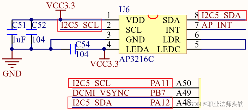
AP3216C 使用的是 I2C5,其中 I2C5_SCL 使用的是 PA11 这个 IO,I2C_SDA 使用的是 PA12 这个 IO。 AP3216C 还有个中断引脚,这里我们没有用到中断功能。
七、程序编写
1. 修改设备树
① IO修改和添加(添加pinctrl)
AP3216C用到了I2C5接口,并且IO口只用达到了 PA11和PA12。打开stm32mp15-pinctrl.dtsi,找到以下内容:
// 第一个状态默认使用,第二个状态睡眠状态使用
i2c5_pins_a: i2c5-0 {
  pins {
    pinmux = <STM32_PINMUX('A', 11, AF4)>, /* I2C5_SCL */
             <STM32_PINMUX('A', 12, AF4)>; /* I2C5_SDA */
    bias-disable;
    drive-open-drain;
    slew-rate = <0>;
  };
};

i2c5_pins_sleep_a: i2c5-1 {
  pins {
    pinmux = <STM32_PINMUX('A', 11, ANALOG)>, /* I2C5_SCL */
             <STM32_PINMUX('A', 12, ANALOG)>; /* I2C5_SDA */
  };
};
② 在 i2c5 节点追加 ap3216c 子节点(添加设备节点)
打开 stm32mp157d-atk.dts 文件,通过节点内容追加的方式,向 i2c5 节点中添加“ap3216c@1e”子节点:
&i2c5 {
  pinctrl-names = "default", "sleep";
  pinctrl-0 = <&i2c5_pins_a>;
  pinctrl-1 = <&i2c5_pins_sleep_a>;
  status = "okay";

  ap3216c@1e {        // 1e是ap3216c设备地址
    compatible = "alientek,ap3216c";
    reg = <0x1e>;
  };
};
修改完成后,重新编译设备树(make dtbs),使用新的设备树启动Linux内核,/sys/bus/i2c/devices 目录下存放着所有 I2C 设备,如果设备树修改正确的话,会在
/sys/bus/i2c/devices 目录下看到一个名为“0-001e”的子目录。这里的1e是ap3216c设备地址,进入0-001e子目录,可以看到"name"文件,输入命令,cat name,就可以看到此设备名字,这里是"ap3216c"。
2. 驱动编写
太久没弄了,复习一下,新建"21_i2c"文件夹,在这个文件夹里创建Vscode,工作区命名为"i2c",工程创建好后新建ap3216c.c和ap3216creg.h两个文件,ap3216c.c 为 AP3216C 的
驱动代码, ap3216creg.h 是 AP3216C 寄存器头文件。先在 ap3216creg.h 中定义好 AP3216C 的寄存器,输入如下内容:
#ifndef AP3216C_H
#define AP3216C_H

#define AP3216C_ADDR 0X1E /* AP3216C 器件地址 */

/* AP3316C 寄存器 */
#define AP3216C_SYSTEMCONG 0x00 /* 配置寄存器 */
#define AP3216C_INTSTATUS 0X01 /* 中断状态寄存器 */
#define AP3216C_INTCLEAR 0X02 /* 中断清除寄存器 */
#define AP3216C_IRDATALOW 0x0A /* IR 数据低字节 */
#define AP3216C_IRDATAHIGH 0x0B /* IR 数据高字节 */
#define AP3216C_ALSDATALOW 0x0C /* ALS 数据低字节 */
#define AP3216C_ALSDATAHIGH 0X0D /* ALS 数据高字节 */
#define AP3216C_PSDATALOW 0X0E /* PS 数据低字节 */
#define AP3216C_PSDATAHIGH 0X0F /* PS 数据高字节 */

#endif
ap3216c.c内容如下:
#include <linux/types.h>
#include <linux/kernel.h>
#include <linux/delay.h>
#include <linux/ide.h>
#include <linux/init.h>
#include <linux/module.h>
#include <linux/errno.h>
#include <linux/gpio.h>
#include <linux/cdev.h>
#include <linux/device.h>
#include <linux/of_gpio.h>
#include <linux/semaphore.h>
#include <linux/timer.h>
#include <linux/i2c.h>
#include <asm/mach/map.h>
#include <asm/uaccess.h>
#include <asm/io.h>
#include "ap3216creg.h"
#define AP3216C_CNT 1
#define AP3216C_NAME "ap3216c"
struct ap3216c_dev
{
dev_t devid; /* 设备号 */
struct cdev cdev; /* cdev */
struct class *class; /* 类 */
struct device *device; /* 设备 */
struct device_node *nd; /* 设备节点 */
struct i2c_client *client; /* i2c 设备 */ // 在i2c中必须存在
unsigned short ir, als, ps; /* 三个光传感器数据 */
};
/*
* @description : 从 ap3216c 读取多个寄存器数据
* @param - dev: ap3216c 设备
* @param - reg: 要读取的寄存器首地址
* @param - val: 读取到的数据
* @param - len: 要读取的数据长度
* @return : 操作结果
*/
static int ap3216c_read_regs(struct ap3216c_dev *dev, u8 reg, void *val, int len)
{
int ret;
struct i2c_msg msg[2]; // 因为这里是读取操作,既要写又要读
struct i2c_client *client = (struct i2c_client *)dev->client; // dev里的client成员强转换为i2c_client结构体赋值给client
/* msg[0] 为发送要读取的首地址 */
msg[0].addr = client->addr; /* ap3216c 地址 */
msg[0].flags = 0; /* 标记为发送数据 */ // 这里表示写操作
msg[0].buf = ® /* 读取的首地址 */
msg[0].len = 1; /* reg 长度 */
/* msg[1] 读取数据 */
msg[1].addr = client->addr; /* ap3216c 地址 */
msg[1].flags = I2C_M_RD; /* 标记为读取数据 */ // 这里是读操作
msg[1].buf = val; /* 读取数据缓冲区 */
msg[1].len = len; /* 要读取的数据长度 */
ret = i2c_transfer(client->adapter, msg, 2);
if (ret == 2)
{
ret = 0;
}
else
{
printk("i2c rd failed=%d reg=%06x len=%d\n", ret, reg, len);
ret = -EREMOTEIO;
}
return ret;
}
/*
* @description : 向 ap3216c 多个寄存器写入数据
* @param - dev: ap3216c 设备
* @param - reg: 要写入的寄存器首地址
* @param - val: 要写入的数据缓冲区
* @param - len: 要写入的数据长度
* @return : 操作结果
*/
static s32 ap3216c_write_regs(struct ap3216c_dev *dev, u8 reg, u8 *buf, u8 len) // s32是有符号的32位整数
{
u8 b[256];
struct i2c_msg msg;
struct i2c_client *client = (struct i2c_client *)dev->client;
b[0] = reg; /* 寄存器首地址 */
memcpy(&b[1], buf, len); /* 将要写入的数据拷贝到数组 b 里面 */
msg.addr = client->addr; /* ap3216c 地址 */
msg.flags = 0; /* 标记为写数据 */
msg.buf = b; /* 要写入的数据缓冲区 */
msg.len = len + 1; /* 要写入的数据长度 */
return i2c_transfer(client->adapter, &msg, 1);
}
/*
* @description: 读取 ap3216c 指定寄存器值,读取一个寄存器
* @param - dev: ap3216c 设备
* @param - reg: 要读取的寄存器
* @return : 读取到的寄存器值
*/
static unsigned char ap3216c_read_reg(struct ap3216c_dev *dev, u8 reg)
{
u8 data = 0;
ap3216c_read_regs(dev, reg, &data, 1);
return data;
}
/*
* @description: 向 ap3216c 指定寄存器写入指定的值,写一个寄存器
* @param - dev: ap3216c 设备
* @param - reg: 要写的寄存器
* @param - data: 要写入的值
* @return : 无
*/
static void ap3216c_write_reg(struct ap3216c_dev *dev, u8 reg, u8 data)
{
u8 buf = 0;
buf = data;
ap3216c_write_regs(dev, reg, &buf, 1); // 这里我觉得可以这样写ap3216c_write_regs(dev, reg, &data, 1);
}
/*
* @description: 读取 AP3216C 的数据,包括 ALS,PS 和 IR, 注意!如果同时
* 打开 ALS,IR+PS 两次数据读取的时间间隔要大于 112.5ms
* @param – ir : ir 数据
* @param - ps : ps 数据
* @param - ps : als 数据
* @return : 无。
*/
void ap3216c_readdata(struct ap3216c_dev *dev)
{
unsigned char i = 0;
unsigned char buf[6];
/* 循环读取所有传感器数据 */
// AP3216C_IRDATALOW = 0x0A,然后+AP3216C_IRDATAHIGH,再加1就是AP3216C_ALSDATALOW,依次类推,总共3个数据,每个数据都有高低位
for (i = 0; i < 6; i++)
{
buf[i] = ap3216c_read_reg(dev, AP3216C_IRDATALOW + i);
}
if (buf[0] & 0X80) /* IR_OF 位为 1,则数据无效 */
dev->ir = 0;
else /* 读取 IR 传感器的数据 */
dev->ir = ((unsigned short)buf[1] << 2) | (buf[0] & 0X03);
// 这个其实就是在组装成16字节,左移8位
dev->als = ((unsigned short)buf[3] << 8) | buf[2]; // 传输als数据
if (buf[4] & 0x40) /* IR_OF 位为 1,则数据无效 */
dev->ps = 0;
else /* 读取 PS 传感器的数据 */
dev->ps = ((unsigned short)(buf[5] & 0X3F) << 4) | (buf[4] & 0X0F);
}
/*
* @description : 打开设备
* @param – inode : 传递给驱动的 inode
* @param - filp : 设备文件, file 结构体有个叫做 private_data 的成员变量
* 一般在 open 的时候将 private_data 指向设备结构体。
* @return : 0 成功;其他 失败
*/
static int ap3216c_open(struct inode *inode, struct file *filp)
{
/* 从 file 结构体获取 cdev 指针, 再根据 cdev 获取 ap3216c_dev 首地址 */
/* 文件操作函数的参数通常只有 filp 结构,没有设备结构体。因此,设备驱动程序需要通过 filp 结构获取设备结构体 */
// 这样做是为了通过 cdev 指针来访问 ap3216c_dev 结构体的其他成员
struct cdev *cdev = filp->f_path.dentry->d_inode->i_cdev;
struct ap3216c_dev *ap3216cdev = container_of(cdev, struct ap3216c_dev, cdev); //(某个成员的指针, 结构体的类型, 结构体中的成员的名称)
/* 初始化 AP3216C */
ap3216c_write_reg(ap3216cdev, AP3216C_SYSTEMCONG, 0x04);
mdelay(50);
ap3216c_write_reg(ap3216cdev, AP3216C_SYSTEMCONG, 0X03);
return 0;
}
/*
* @description : 从设备读取数据
* @param - filp : 要打开的设备文件(文件描述符)
* @param - buf : 返回给用户空间的数据缓冲区
* @param - cnt : 要读取的数据长度
* @param - offt : 相对于文件首地址的偏移
* @return : 读取的字节数,如果为负值,表示读取失败
*/
static ssize_t ap3216c_read(struct file *filp, char __user *buf, size_t cnt, loff_t *off)
{
short data[3];
long err = 0;
struct cdev *cdev = filp->f_path.dentry->d_inode->i_cdev;
struct ap3216c_dev *dev = container_of(cdev, struct ap3216c_dev, cdev);
ap3216c_readdata(dev);
data[0] = dev->ir;
data[1] = dev->als;
data[2] = dev->ps;
err = copy_to_user(buf, data, sizeof(data));
return 0;
}
/*
* @description : 关闭/释放设备
* @param - filp : 要关闭的设备文件(文件描述符)
* @return : 0 成功;其他 失败
*/
static int ap3216c_release(struct inode *inode, struct file *filp)
{
return 0;
}
/* AP3216C 操作函数 */
static const struct file_operations ap3216c_ops = {
.owner = THIS_MODULE,
.open = ap3216c_open,
.read = ap3216c_read,
.release = ap3216c_release,
};
/*
* @description : i2c 驱动的 probe 函数,当驱动与设备匹配以后此函数就会执行
* @param – client : i2c 设备
* @param - id : i2c 设备 ID
* @return : 0,成功;其他负值,失败
*/
static int ap3216c_probe(struct i2c_client *client, const struct i2c_device_id *id)
{
int ret;
struct ap3216c_dev *ap3216cdev;
ap3216cdev = devm_kzalloc(&client->dev, sizeof(*ap3216cdev), GFP_KERNEL); // 由于 linux 内核不推荐使用全局变量, 要使用内存的就用 devm_kzalloc 之类的函数去申请空间
if (!ap3216cdev)
return -ENOMEM;
/* 注册字符设备驱动 */
/* 1、创建设备号 */
ret = alloc_chrdev_region(&ap3216cdev->devid, 0, AP3216C_CNT, AP3216C_NAME);
if (ret < 0)
{
pr_err("%s Couldn't alloc_chrdev_region, ret=%d\r\n", AP3216C_NAME, ret);
return -ENOMEM;
}
/* 2、初始化 cdev */
ap3216cdev->cdev.owner = THIS_MODULE;
cdev_init(&ap3216cdev->cdev, &ap3216c_ops);
/* 3、添加一个 cdev */
ret = cdev_add(&ap3216cdev->cdev, ap3216cdev->devid, AP3216C_CNT);
if (ret < 0)
{
goto del_unregister;
}
/* 4、创建类 */
ap3216cdev->class = class_create(THIS_MODULE, AP3216C_NAME);
if (IS_ERR(ap3216cdev->class))
{
goto del_cdev;
}
/* 5、创建设备 */
ap3216cdev->device = device_create(ap3216cdev->class, NULL, ap3216cdev->devid, NULL, AP3216C_NAME);
if (IS_ERR(ap3216cdev->device))
{
goto destroy_class;
}
ap3216cdev->client = client;
/* 保存 ap3216cdev 结构体 */
i2c_set_clientdata(client, ap3216cdev);
return 0;
destroy_class:
device_destroy(ap3216cdev->class, ap3216cdev->devid);
del_cdev:
cdev_del(&ap3216cdev->cdev);
del_unregister:
unregister_chrdev_region(ap3216cdev->devid, AP3216C_CNT);
return -EIO;
}
/*
* @description : i2c 驱动的 remove 函数,移除 i2c 驱动的时候此函数会执行
* @param - client : i2c 设备
* @return : 0,成功;其他负值,失败
*/
static int ap3216c_remove(struct i2c_client *client)
{
struct ap3216c_dev *ap3216cdev = i2c_get_clientdata(client);
/* 注销字符设备驱动 */
/* 1、删除 cdev */
cdev_del(&ap3216cdev->cdev);
/* 2、注销设备号 */
unregister_chrdev_region(ap3216cdev->devid, AP3216C_CNT);
/* 3、注销设备 */
device_destroy(ap3216cdev->class, ap3216cdev->devid);
/* 4、注销类 */
class_destroy(ap3216cdev->class);
return 0;
}
/* 传统匹配方式 ID 列表 */
static const struct i2c_device_id ap3216c_id[] = {
{"alientek,ap3216c", 0},
{}};
/* 设备树匹配列表 */
static const struct of_device_id ap3216c_of_match[] = {
{.compatible = "alientek,ap3216c"},
{/* Sentinel */}};
/* i2c 驱动结构体 */
static struct i2c_driver ap3216c_driver = {
.probe = ap3216c_probe,
.remove = ap3216c_remove,
.driver = {
.owner = THIS_MODULE,
.name = "ap3216c",
.of_match_table = ap3216c_of_match,
},
.id_table = ap3216c_id,
};
/*
* @description : 驱动入口函数
* @param : 无
* @return : 无
*/
static int __init ap3216c_init(void)
{
int ret = 0;
ret = i2c_add_driver(&ap3216c_driver);
return ret;
}
/*
* @description : 驱动出口函数
* @param : 无
* @return : 无
*/
static void __exit ap3216c_exit(void)
{
i2c_del_driver(&ap3216c_driver);
}
/* module_i2c_driver(ap3216c_driver) */
module_init(ap3216c_init);
module_exit(ap3216c_exit);
MODULE_LICENSE("GPL");
MODULE_AUTHOR("ALIENTEK");
MODULE_INFO(intree, "Y");3.编写测试App
这个比较简单,就是一直在读取ap3216C的设备文件,从而得到ir、als和ps三个值。
#include "stdio.h"
#include "unistd.h"
#include "sys/types.h"
#include "sys/stat.h"
#include "sys/ioctl.h"
#include "fcntl.h"
#include "stdlib.h"
#include "string.h"
#include <poll.h>
#include <sys/select.h>
#include <sys/time.h>
#include <signal.h>
#include <fcntl.h>

/*
 * @description : main 主程序
 * @param - argc : argv 数组元素个数
 * @param - argv : 具体参数
 * @return : 0 成功;其他 失败
 */
int main(int argc, char *argv[])
{
    int fd;
    char *filename;
    unsigned short databuf[3];
    unsigned short ir, als, ps;
    int ret = 0;

    if (argc != 2)
    {
        printf("Error Usage!\r\n");
        return -1;
    }

    filename = argv[1];
    fd = open(filename, O_RDWR);
    if (fd < 0)
    {
        printf("can't open file %s\r\n", filename);
        return -1;
    }

    while (1)
    {
        ret = read(fd, databuf, sizeof(databuf));
        if (ret == 0)
        {                     /* 数据读取成功 */
            ir = databuf[0];  /* ir 传感器数据 */
            als = databuf[1]; /* als 传感器数据 */
            ps = databuf[2];  /* ps 传感器数据 */
            printf("ir = %d, als = %d, ps = %d\r\n", ir, als, ps);
        }
        usleep(200000); /*100ms */
    }
    close(fd); /* 关闭文件 */
    return 0;
}
八、运行测试
首先编写 Makefile 文件:
KERNELDIR := /home/alientek/linux/atk-mpl/linux/my_linux/linux-5.4.31
CURRENT_PATH := $(shell pwd)

obj-m := ap3216c.o

build: kernel_modules

kernel_modules:
	$(MAKE) -C $(KERNELDIR) M=$(CURRENT_PATH) modules

clean:
	$(MAKE) -C $(KERNELDIR) M=$(CURRENT_PATH) clean
之后编译 ap3216c.c 和 ap3216cApp.c 文件:
make
arm-none-linux-gnueabihf-gcc ap3216cApp.c -o ap3216cApp
将编译好的 ap3216cApp 和 ap3216c.ko 复制:
sudo cp ap3216cApp ap3216c.ko /home/alientek/linux/nfs/rootfs/lib/modules/5.4.31/ -f开启开发板,进入 lib/modules/5.4.31,输入以下命令:
cd lib/modules/5.4.31/加载驱动:
depmod
modprobe ap3216c.ko
当驱动模块加载成功以后使用 ap3216cApp 来测试,输入如下命令:
./ap3216cApp /dev/ap3216c 测试 APP 会不断的从 AP3216C 中读取数据,然后输出到终端上,可以拿手电筒照AP3216C,或者手指靠近 AP3216C 来观察传感器数据有没有变化。





![[HCIE] IPSec-VPN (手工模式)](https://img-blog.csdnimg.cn/6be76ad4c18848b0ad48afd0635349ab.png)


