LedControl 库最初是为基于 8 位 AVR 处理器的 Arduino 板编写的。用于通过MAX7219芯片控制LED矩阵和7段数码管。但由于该代码不使用处理器的任何复杂的内部功能,因此具有高度可移植性,并且应该在任何支持 和 功能的 Arduino(类似)板上pinMode()运行digitalWrite() 。
单个 MAX72XX Led 驱动器能够控制 64 个 Led。该库支持多达 8 个菊花链式 MAX72XX 驱动程序。控制 512 个 LED 对于大多数用途来说应该绰绰有余。
库初始化
要将库包含到 Arduino 代码中,您必须编写几行初始化代码。
将库添加到您的草图中
这与任何其他 Arduino 库一样工作,您可以使用 Include LibraryIDE 中的菜单功能,或者只需添加一个
#include "LedControl.h"
在草图的顶部声明。
创建 LedControl 变量
所有库 API 函数都是通过类型变量调用的, LedControl该变量应该在草图的顶部定义,以便项目代码的其余部分可以访问它。
库初始化的典型代码如下所示:
/* 包含 LedControl 库 */
#include "LedControl.h"

/* 创建一个新的 LedControl 变量。
* 我们使用 Arduino 上的引脚 12,11 和 10 作为 SPI 接口
* 引脚 12 连接到第一个 MAX7221 的 DATA IN 引脚
* 引脚 11 连接到第一个 MAX7221 的 CLK 引脚
* 引脚 10 连接到到第一个 MAX7221 的 LOAD(/CS) 引脚
* 只有一个 MAX7221 连接到 arduino
*/
LedControl  lc1 = LedControl ( 12 , 11 , 10 , 1 );
我们与 MAX72XX 器件通信的变量的初始化代码有 4 个参数。前 3 个参数是 Arduino 上连接到 MAX72XX 的引脚号。这些可以是 arduino 上的任何数字 IO 引脚。在示例中12,引脚 、11和10任意选择。库代码不会以任何方式对引脚号进行完整性检查以确保其 有效。传递一些愚蠢的东西(pin 123??),或者只是 错误的pin号会破坏代码,而不会发出通知或错误消息。您不必将 IO 引脚初始化为输出或将它们设置为特定状态,库将为您完成这些工作。
第四个参数LedControl(dataPin,clockPin,csPin,numDevices)是与此一起使用的级联 MAX72XX 器件的数量LedControl。该库可以通过单个变量寻址最多 8 个设备LedControl。添加到链中的每个设备都会带来一些性能损失,但无论您设置多少个设备,库代码使用的内存量都将保持不变。由于LedControl无法寻址超过 8 个设备,因此此处仅允许使用 1..8 之间的值。
如果您的草图需要控制超过 8 个 MAX72XX,则 LedControl需要创建另一个使用 arduino 板上 3 个不同引脚的变量。
#include "LedControl.h"
// 为前 8 个设备创建一个 LedControl...
LedControl  lc1 = LedControl ( 12 , 11 , 10 , 8 );
// ...以及接下来 8 个设备的另一个。
LedControl  lc2 = LedControl ( 9,8,7,8 ) ; _ _ _ _ _
获取连接设备的数量
无法从代码中读取 IO 引脚编号,但有一个函数可以获取连接到LedControl.
/* 获取连接到此 LedControl 的最大设备数。
* 返回 :
* int 连接到此 LedControl 的设备数量 */
int  LedControl : :getDeviceCount ();
该函数用于循环访问所连接的 MAX72XX 器件的完整列表。下面是一段代码,用于将所有 MAX72XX 器件从省电模式切换到正常工作模式。即使shutdown(addr)稍后介绍该函数,这段代码背后的想法也应该很清楚。
#include "LedControl.h"

lc1=LedControl(12,11,10,5);

void setup() {
    for(int index=0;index<lc1.getDeviceCount();index++) {
        lc1.shutdown(index,false);
    }
}
我们通过从 0 到 的索引迭代设备列表 getDeviceCount()-1。索引是每个设备的地址。该地址是每个在设备上设置功能或 (Led-) 值的函数的第一个参数。请注意,getDeviceCount()返回连接的设备数量,但 设备的地址从第一个设备的 0 开始,第二个设备的地址从 1 开始,最后一个设备的地址从 getDeviceCount()-10 开始。
省电模式
LED 点亮时会消耗相当多的能量。电池供电的设备需要一种节省电量的方法,可以在用户不需要时关闭整个显示屏。MAX72XX 支持电源关断模式。
在关机模式下,设备会关闭显示屏上的所有 LED,但数据会保留。当设备退出关闭模式时,相同的 LED 将像进入睡眠状态之前一样亮起。甚至可以在关闭模式期间发送新数据。当设备重新激活时,新数据将出现在显示屏上。以下是7 段显示屏上不可见倒计时的示例:
void countDown() {
    int i=9;
    lc.setDigit(0,(byte)i,false);
    //The digit '9' appears on the display
    delay(1000);
    //Go into shutdown mode
    lc.shutdown(0,true);
    //and count down silently
    while(i>1) {
        //data is updated, but not shown
        lc.setDigit(0,(byte)i,false);
        i--;
        delay(1000);
    }
    //Coming out of shutdown mode we have already reached '1'
    lc.shutdown(0,false);
    lc.setDigit(0,(byte)i,false);
}
这是方法的原型LedControl.shutdown(addr,status)
/*
 * Set the shutdown (power saving) mode for the device
 * Params :
 *   addr   The address of the display to control
 *   status If true the device goes into power-down mode. Set to false
 *          for normal operation.
 */
 void shutdown(int addr, bool status);
注意:当 Arduino 上电时,始终MAX72XX处于关闭模式。
限制位数 (ScanLimit)
这是一种专家功能,大多数图书馆用户并不真正需要。由于该库将其初始化 MAX72XX 为安全的默认值,因此您不必仅仅为了让您的硬件正常工作而阅读本节
当创建新的 LedControl 时,它将激活所有设备上的所有 8 位数字。每个亮起的数字将由驱动数字的多路复用器电路打开 1/8 秒。如果您有任何理由限制扫描数字的数量,则 LED 会更频繁地打开,因此会打开更长的时间。
将扫描限制设置为 4 的效果是,点亮的 LED 现在打开 1/4 秒,而不是标准的 1/8 秒。必须MAX72XX在较长的时间内为分段驱动器提供电流。
您应该仔细阅读数据表的相关部分MAX72XX!实际上,通过选择错误的电阻器组合,限制流过 LED 的电流和设备扫描的位数,可能会损坏 LED。调整扫描限制的唯一原因是显示器看起来太暗。但这很可能是由于启动时强度没有提高。这是原型,供有需要的人使用:MAX72XXRSetsetScanLimit()
/* 设置要显示的位数(或行数)。
* 有关扫描限制对显示器亮度的副作用,请参阅数据表。
* 参数: * addr 要控制的显示器的地址* limit 要显示的位数*/
void setScanLimit ( int addr , int limit ) ;
设置显示亮度
决定显示器亮度的三个因素。
- Rset限制流过 LED 的最大电流的电阻值。
- 显示器的扫描限制。(如果您阅读了本节,您已经知道我建议将此选项保留为安全默认值。)
- 以及一个允许通过软件控制 LED 亮度的命令。
通过该setIntensity(int addr, int intensity)方法,LED 的亮度可以按 16 个离散步骤进行设置 ( 0..15)。值越高,显示越亮。大于 15 的值将被丢弃,而不改变亮度。即使是最低值也0不会完全关闭显示屏。
/* Set the brightness of the display.
 * Params:
 *   addr the address of the display to control
 *   intensity the brightness of the display.
void setIntensity(int addr, int intensity);
设备初始化
当创建新的库时,LedControl库将使用以下命令初始化硬件
- 显示清除
- 强度设置为最小值
- 设备处于省电模式
- 激活设备上的最大位数
启动时显示空白可能是每个人都想要的。但当强度处于最低且设备处于关闭模式时,在启动配置中不会点亮任何 LED。大多数用户将在函数内进行自己的初始化setup()。下面是一段代码,可用作创建一个模板,LedControl一旦显示数据到达,该代码就可以以中等亮度点亮 LED。
#include "LedControl.h"

LedControl lc=LedControl(12,11,10,1);

void setup() {
    //wake up the MAX72XX from power-saving mode
    lc.shutdown(0,false);
    //set a medium brightness for the Leds
    lc.setIntensity(0,8);
}
LED矩阵
所有初始化代码就位后,现在可以控制一些 LED 了。

清除显示
该函数的名称LedControl.clearDisplay(addr)已经暗示了它的作用。
/* 关闭显示屏上的所有 LED。
* Params:
* addr 要控制的显示器的地址
*/
void  clearDisplay ( int * addr ) ;
所选设备上的所有 LED 均关闭。重要的是要了解这与保留数据的关闭模式不同。
控制单个 LED
这是打开或关闭单个 Led 的函数原型。
/* 设置单个 LED 的状态。
* 参数 :
* 显示器的地址
* row Led 的行 (0..7)
* col Led 的列 (0..7)
* state 如果为 true,则 LED 打开,如果为 false,则打开off
*/
void  setLed ( int  addr ,  int  row ,  int  col ,  boolean  state ) ;
addr和参数背后的想法state应该很清楚,但是row和column参数指的是什么?这取决于矩阵MAX72XX和矩阵之间的接线。-libraryLedControl假定此示意图中使用的设置:
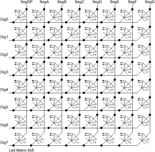
矩阵中有 8 行(索引从 0..7 开始)和 8 列(索引也从 0..7 开始)。如果要点亮位于顶部第三行最右侧的 Led,则2.7必须使用 Led 的索引作为行和列参数。
此代码摘录显示了第一个 MAX72XX 器件上的 LED 数量设置情况
//打开addr=0处设备第3行第8列的LED
lc.setLed(0,2,7,true);
//现在 LED 位于第 0 行,从左侧数第二个
lc.setLed(0,0,1,true);
延迟(500);
//关闭第一个LED灯(第二个保持打开状态)
lc.setLed(0,2,7,false);
该setLed()函数适合点亮几个 LED,但如果需要更新更多 LED,则需要很多行代码。因此,库中还有两个函数,可以使用单个命令控制完整的行和列。
控制矩阵的行
- 函数setRow(addr,row,value)有 3 个参数。第一个是我们已经熟悉的设备地址。第二个是需要更新的行,第三个是要为此行设置的值。
该value参数采用 8 位宽字节,其中设置的每个位1 代表一个点亮的 LED,设置为0要关闭的 LED 的每个位。
例如,标记为红色的 LED 将打开,所有其他 LED 将关闭。
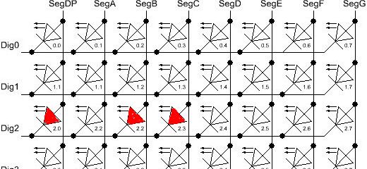
要更新的行的索引为2(从顶部数)。必须将参数value 设置为字节值才能点亮 LED。最简单的方法是将标准头文件包含<binary.h>到您的草图中。该值以二进制编码写入,是设置的位1和要打开的 LED 之间的精确映射。
//将此文件包含在草图的顶部
<二进制.h>

// ...省略初始化代码...

//设置第一个设备的第三行(索引=2)的LED
lc.setRow(0,2,B10110000);
当无法以二进制编码指定值时,将每个位的十进制值映射到其影响的 Led 的简单表会有所帮助。底部的两行显示要计算的示例的十进制值。
| Led2.0 | Led2.1 | Led2.2 | Led2.3 | Led2.4 | Led2.5 | Led2.6 | Led2.7 | |
|---|---|---|---|---|---|---|---|---|
| Bit-Value | 128 | 64 | 32 | 16 | 8 | 4 | 2 | 1 |
| Led On? | Yes | No | Yes | Yes | No | No | No | No |
| Row-Value | 128 | 0 | 32 | 16 | 0 | 0 | 2 | 0 |
value=176 (128+32+16)
该语句更新了Arduino 附加的lc.setRow(0,2,176)第一行的第三行。MAX72XX
显然 ,对所有 LED 连续setRow()调用八次要快得多。setLed()a 的硬件MAX72XX 使得该函数也比下一节中介绍的函数setRow()快 8 倍 。setColumn()如果草图代码的性能是重要因素,请setRow() 尽可能使用该函数。
函数原型
/* 将一行中的所有 8 个 Led 设置为新状态
* 参数:
* 显示器的地址
* 要设置的行行 (0..7)
* 每个位设置为 1 的值将点亮相应的 Led。
*/
void  setRow ( int  addr ,  int  row , 字节 值) ;
控制矩阵的列
-setColumn()函数的工作方式与该命令类似setRow(),但会更新垂直列中的 8 个 LED。
同样,红色标记的 LED 灯将打开,所有其他 LED 灯将关闭。
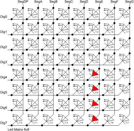
这次,第 6 列底部的 4 个 LED 将被点亮。对于二进制编码,值中最左边的位指的是列顶部的 LED。
//将此文件包含在草图的顶部
<二进制.h>

// ...省略初始化代码...

//设置第一个设备的第三行(索引=2)的LED
lc.setRow(0,2,B00001111);
setRow()如果值的二进制编码不是一种选择,则与 参考资料部分中的表类似的表会有所帮助。
| LED2.0 | LED2.1 | LED2.2 | LED2.3 | LED2.4 | LED2.5 | LED2.6 | LED2.7 | |
|---|---|---|---|---|---|---|---|---|
| 位值 | 128 | 64 | 32 | 16 | 8 | 4 | 2 | 1 |
| 带领 | 是的 | 不 | 是的 | 是的 | 不 | 不 | 不 | 不 |
| 行值 | 128 | 0 | 32 | 16 | 0 | 0 | 2 | 0 |
=15 (8+4+2+1)
函数原型:
/* 将一列中的所有 8 个 Led 设置为新状态
* 参数:
* 显示器的地址
* 要设置的列列 (0..7)
* 每个位设置为 1 的值将点亮相应的 Led。
*/
void  setColumn ( int  addr ,  int  col , 字节 值) ;
控制 7 段显示器

在 7 段显示器上打印数字
7 段显示器最常见的用途是打印数字。LedControl 库有一个函数,只需接受字节类型的参数并在指定列上打印相应的数字。数字的有效值为从0到15,以允许显示十六进制值。大于 15(或负值)的值将被默默丢弃。该函数还提供了一个参数来打开或关闭列上的小数点。
以下是在显示屏上以 4 位数字打印 int 值 (-999..999) 的代码摘录。
void printNumber(int v) {
    int ones;
    int tens;
    int hundreds;

    boolean negative=false;

    if(v < -999 || v > 999)
        return;
    if(v<0) {
        negative=true;
        v=v*-1;
    }
    ones=v%10;
    v=v/10;
    tens=v%10;
    v=v/10; hundreds=v;
    if(negative) {
        //print character '-' in the leftmost column
        lc.setChar(0,3,'-',false);  }
    else {
        //print a blank in the sign column
        lc.setChar(0,3,' ',false);
    }
    //Now print the number digit by digit
    lc.setDigit(0,2,(byte)hundreds,false);
    lc.setDigit(0,1,(byte)tens,false);
    lc.setDigit(0,0,(byte)ones,false);
}
该函数的原型:
/* Display a (hexadecimal) digit on a 7-Segment Display
 * Params:
 *  addr   address of the display
 *  digit  the position of the digit on the display (0..7)
 *  value  the value to be displayed. (0x00..0x0F)
 *  dp     sets the decimal point.
*/
void setDigit(int addr, int digit, byte value, boolean dp);
- 参数digit必须在 0..7 范围内,因为 MAX72XX 可以控制 7 段显示器上最多 8 位数字。
在 7 段显示器上打印字符
在 7 段显示器上具有(视觉)意义的字符集有限。常见的用途是在-前面添加负值的字符以及表示整数十六进制值的 'A'..'F' 中的 6 个字符。
-setChar(addr,digit,value,dp)函数接受 7 位 ASCII 编码范围内的 char 类型值。由于可识别的模式有限,大多数定义的字符都会打印 -char <SPACE>。但有相当多的字符在 7 段显示器上有意义。
这是可打印字符集:
0 1 2 3 4 5 6 7 8 9A a(打印大写字母)B b(打印小写)C c(打印小写)D d(打印小写)E e(打印大写字母)F f(打印大写字母)H h(打印大写字母)L l(打印大写字母)P p(打印大写字母)-(减号). ,(点亮小数点)_(下划线)<SPACE>(空白或空格字符)
十六进制字符 ( 0..F) 已在字符值 0x00...0x0F 处重新定义。这使得混合数字和字符值成为可能。- 函数的字节值setDigit()可以与 一起使用setChar(),并将打印该值的十六进制表示形式。
该函数的原型看起来与显示数字的函数原型非常相似。
/* Display a character on a 7-Segment display.
 * Params:
 *   addr  address of the display
 *   digit the position of the character on the display (0..7)
 *   value the character to be displayed.
 *   dp    sets the decimal point.
*/
void setChar(int addr, int digit, char value, boolean dp);
完整的代码:
#include "LedControl.h"

LedControl lc=LedControl(11,13,10,1);

unsigned long delaytime=10;

void setup() {

  lc.shutdown(0,false);

  lc.setIntensity(0,15);

  lc.clearDisplay(0);

}

void writeArduinoOnMatrix() {


  byte a[5]={B01111110,B10001000,B10001000,B10001000,B01111110};

  byte r[5]={B00111110,B00010000,B00100000,B00100000,B00010000};

  byte d[5]={B00011100,B00100010,B00100010,B00010010,B11111110};

  byte u[5]={B00111100,B00000010,B00000010,B00000100,B00111110};

  byte i[5]={B00000000,B00100010,B10111110,B00000010,B00000000};

  byte n[5]={B00111110,B00010000,B00100000,B00100000,B00011110};

  byte o[5]={B00011100,B00100010,B00100010,B00100010,B00011100};


  lc.setRow(0,0,a[0]);

  lc.setRow(0,1,a[1]);

  lc.setRow(0,2,a[2]);

  lc.setRow(0,3,a[3]);

  lc.setRow(0,4,a[4]);

  delay(delaytime);

  lc.setRow(0,0,r[0]);

  lc.setRow(0,1,r[1]);

  lc.setRow(0,2,r[2]);

  lc.setRow(0,3,r[3]);

  lc.setRow(0,4,r[4]);

  delay(delaytime);

  lc.setRow(0,0,d[0]);

  lc.setRow(0,1,d[1]);

  lc.setRow(0,2,d[2]);

  lc.setRow(0,3,d[3]);

  lc.setRow(0,4,d[4]);

  delay(delaytime);

  lc.setRow(0,0,u[0]);

  lc.setRow(0,1,u[1]);

  lc.setRow(0,2,u[2]);

  lc.setRow(0,3,u[3]);

  lc.setRow(0,4,u[4]);

  delay(delaytime);

  lc.setRow(0,0,i[0]);

  lc.setRow(0,1,i[1]);

  lc.setRow(0,2,i[2]);

  lc.setRow(0,3,i[3]);

  lc.setRow(0,4,i[4]);

  delay(delaytime);

  lc.setRow(0,0,n[0]);

  lc.setRow(0,1,n[1]);

  lc.setRow(0,2,n[2]);

  lc.setRow(0,3,n[3]);

  lc.setRow(0,4,n[4]);

  delay(delaytime);

  lc.setRow(0,0,o[0]);

  lc.setRow(0,1,o[1]);

  lc.setRow(0,2,o[2]);

  lc.setRow(0,3,o[3]);

  lc.setRow(0,4,o[4]);

  delay(delaytime);

  lc.setRow(0,0,0);

  lc.setRow(0,1,0);

  lc.setRow(0,2,0);

  lc.setRow(0,3,0);

  lc.setRow(0,4,0);

  delay(delaytime);

}


void rows() {

  for(int row=0;row<8;row++) {

    delay(delaytime);

    lc.setRow(0,row,B10100000);

    delay(delaytime);

    lc.setRow(0,row,(byte)0);

    for(int i=0;i<row;i++) {

      delay(delaytime);

      lc.setRow(0,row,B10100000);

      delay(delaytime);

      lc.setRow(0,row,(byte)0);

    }

  }

}


void columns() {

  for(int col=0;col<8;col++) {

    delay(delaytime);

    lc.setColumn(0,col,B10100000);

    delay(delaytime);

    lc.setColumn(0,col,(byte)0);

    for(int i=0;i<col;i++) {

      delay(delaytime);

      lc.setColumn(0,col,B10100000);

      delay(delaytime);

      lc.setColumn(0,col,(byte)0);

    }

  }

}


void single() {

  for(int row=0;row<8;row++) {

    for(int col=0;col<8;col++) {

      delay(delaytime);

      lc.setLed(0,row,col,true);

      delay(delaytime);

      for(int i=0;i<col;i++) {

        lc.setLed(0,row,col,false);

        delay(delaytime);

        lc.setLed(0,row,col,true);

        delay(delaytime);

      }

    }

  }

}


void loop() {

  writeArduinoOnMatrix();

  rows();

  columns();

  single();

}


