文章目录
- arduino - NUCLEO-H723ZG - test
- 概述
- 笔记
- 物理串口
- 软串口
- 备注
- END
arduino - NUCLEO-H723ZG - test
概述
准备向NUCLEO-H723ZG上移植西门子飞达控制的Arduino程序.
先确认一下知识点和效果.
笔记
物理串口
NUCLEO-H723ZG在STM32 Arduino 库中, 只提供了一个串口 Serail.
先看看这个串口在板子上哪个位置?
官方板子的左右, 各有一个USB接口.
物理连接
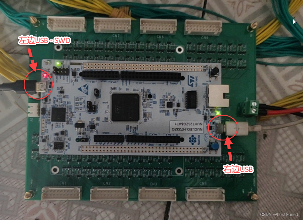
左边USB端口是Arduino用的SWD端口, 用来上传程序和单步调试. 插入电脑后, 电脑上会出现一个虚拟串口.
右边USB端口插入后, 电脑上没有虚拟串口出现.
测试程序
void setup() {
  // put your setup code here, to run once:

  // Serial.begin(9600); // basic usage

  // HardwareSerial.h
//   #ifdef UART_WORDLENGTH_7B
//   #define SERIAL_7N1 0x04
//   #define SERIAL_7N2 0x0C
//   #define SERIAL_6E1 0x22
//   #define SERIAL_6E2 0x2A
//   #define SERIAL_6O1 0x32
//   #define SERIAL_6O2 0x3A
// #endif
// #define SERIAL_8N1 0x06
// #define SERIAL_8N2 0x0E
// #define SERIAL_7E1 0x24
// #define SERIAL_8E1 0x26
// #define SERIAL_7E2 0x2C
// #define SERIAL_8E2 0x2E
// #define SERIAL_7O1 0x34
// #define SERIAL_8O1 0x36
// #define SERIAL_7O2 0x3C
// #define SERIAL_8O2 0x3E

  Serial.begin(9600, SERIAL_8N1); // advance usage


}

void loop() {
  // put your main code here, to run repeatedly:
  do {
    Serial.println("hello");
    delay(1000);
  } while (true);
}
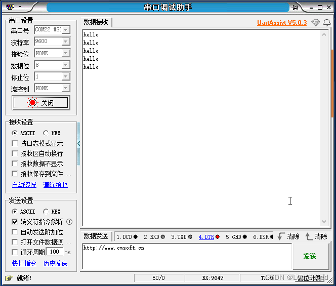
上传程序后, 用串口助手打开电脑上的虚拟串口(由开发板左边USB插入虚拟出的串口). 可以看到开发板程序通过串口Serial发来的信息.
通过实验可知, Arduino程序可用的串口只能是和左边USB-SWD端口重合的虚拟串口. 右边的USB端口在Arduino程序中没有作用.
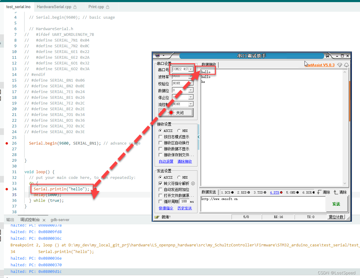
虽然只有一个USB端口来调试和通讯, 但是开发板虚拟出来的串口和单步用的SWD端口并不冲突, 可以同时进行.
软串口
对于飞达控制板, 因为都是用串口来操作, 没有那么多物理串口, 只能是用软串口.
对软串口的使用细节做了测试.
硬件连接如下:
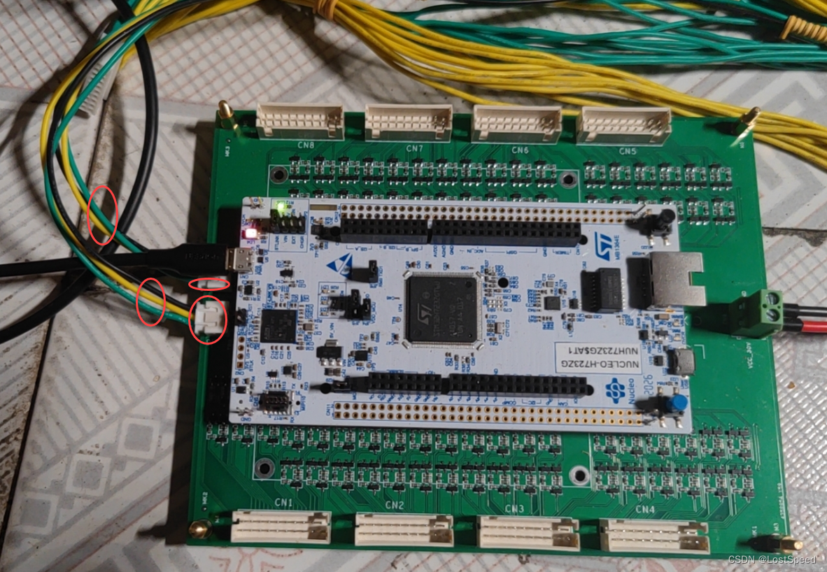

这2个软串口是直接从NUCLEO-H723ZG的GPIO引出来的, 只要对这2个软串口的使用清楚了就行了.
其他软串口经过了30V到飞达, 不好写测试程序. 用法和这2个软串口相同.
测试程序如下:
#include <SoftwareSerial.h>

// SoftwareSerial(uint16_t receivePin, uint16_t transmitPin, bool inverse_logic = false);

// UART_DEBUG1_TX D16_CN7_1, UART_DEBUG1_RX D15_CN7_2
SoftwareSerial UartDebug1(15, 16);

// UART_DEBUG2_TX D17_CN7_3, UART_DEBUG2_RX D14_CN7_4
SoftwareSerial UartDebug2(14, 17);

void setup() {
  // put your setup code here, to run once:

  // Serial.begin(9600); // basic usage

  // HardwareSerial.h
  //   #ifdef UART_WORDLENGTH_7B
  //   #define SERIAL_7N1 0x04
  //   #define SERIAL_7N2 0x0C
  //   #define SERIAL_6E1 0x22
  //   #define SERIAL_6E2 0x2A
  //   #define SERIAL_6O1 0x32
  //   #define SERIAL_6O2 0x3A
  // #endif
  // #define SERIAL_8N1 0x06
  // #define SERIAL_8N2 0x0E
  // #define SERIAL_7E1 0x24
  // #define SERIAL_8E1 0x26
  // #define SERIAL_7E2 0x2C
  // #define SERIAL_8E2 0x2E
  // #define SERIAL_7O1 0x34
  // #define SERIAL_8O1 0x36
  // #define SERIAL_7O2 0x3C
  // #define SERIAL_8O2 0x3E

  Serial.begin(115200, SERIAL_8N1);  // advance usage
  Serial.println("v1.0.0.10 begin...\r\n");

  // Start each software serial port
  UartDebug1.begin(115200);  // 软串口只能简单的设置波特率, 其他通讯参数是默认的(N81)
  UartDebug1.listen();

  UartDebug1.write('U');
  UartDebug1.write('a');
  UartDebug1.write('r');
  UartDebug1.write('t');
  UartDebug1.write('1');
  UartDebug1.write('\r');
  UartDebug1.write('\n');

  UartDebug2.begin(115200);
  UartDebug2.listen();

  UartDebug2.write('U');
  UartDebug2.write('a');
  UartDebug2.write('r');
  UartDebug2.write('t');
  UartDebug2.write('2');
  UartDebug2.write('\r');
  UartDebug2.write('\n');
}

void loop() {
  // put your main code here, to run repeatedly:
  char inByte = '\0';
  int i = 0;
  char szBuf[256];

  do {
    memset(szBuf, 0, sizeof(szBuf));
    // sprintf(szBuf, "loop cnt : %d", ++i);
    // Serial.println(szBuf);


    // while (UartDebug1.available() > 0) {
    //   inByte = UartDebug1.read();
    //   UartDebug1.write(inByte);
    // }

    // 如果前面有UartDebug1的接收, UartDebug2的接收就不好使, 收不到东西
    // while (UartDebug2.available() > 0) {
    //   inByte = UartDebug2.read();
    //   UartDebug1.write(inByte);
    // }

    // UartDebug1.write('1');
    // UartDebug2.write('2');

    // 确实, 如果前面有其他软串口在接收东西, 后面的软串口就收不到发来的东西
    // 但是发送不受影响
    // 这种情况也就正好适合飞达控制原理图这种(多个飞达都是分别发送, 但是多个飞达的接收都是汇到了一根接收线的情况)
    // 如果将软串口作为调试串口, 也只适合上报信息, 用于接受信息进行处理就不合适了.
    // while (UartDebug1.available() > 0) {
    //   inByte = UartDebug1.read();
    //   UartDebug2.write(inByte);
    // }

    // Serial.println("sleep 1000\r\n");

    // 这种软串口只适合做纯发送或者纯接收.
    // 感觉多个软串口用的都是一个定时器做的
    UartDebug1.listen();
    while (UartDebug1.available() > 0) {
      inByte = UartDebug1.read();
      sprintf(szBuf, "UartDebug1 send me : %c", inByte);
      Serial.println(szBuf);
    }

    UartDebug2.listen();
    while (UartDebug2.available() > 0) {
      inByte = UartDebug2.read();
      sprintf(szBuf, "UartDebug2 send me : %c", inByte);  // 只有给串口2发送东西, 才能收到
      Serial.println(szBuf);
    }

    // 从软串口实现看, 监听接收的软串口只能是当前激活的一个, 所以无法做到用多个软串口来接收. 软串口性能有限啊
    /*
          bool SoftwareSerial::listen()
      {
        if (active_listener != this) {
          // wait for any transmit to complete as we may change speed
          while (active_out);
          if (active_listener != nullptr) {
            active_listener->stopListening();
          }
          rx_tick_cnt = 1; // 1 : next interrupt will decrease rx_tick_cnt to 0 which means RX pin level will be considered.
          rx_bit_cnt = -1; // rx_bit_cnt = -1 :  waiting for start bit
          setSpeed(_speed);
          active_listener = this;
          if (!_half_duplex) {
            active_in = this;
          } else if (!active_out) {
            setRXTX(true);
          }
          return true;
        }
        return false;
      }
    */

    // delay(1000);
    delay(1);
  } while (true);
}
通过测试, 发现软串口只能用于发送, 或者只能用于接收. 否则收不到软串口发来的内容.
原因: 软串口的实现使用定时器做的, 做接收的只能是一个软串口.
根据软串口的实现原理, 使用软串口的原理图, 也就像官方飞达控制板那样最理想.
每个飞达用一个GPIO模拟串口发送, 所有飞达的接收端都汇总到一个GPIO上, 用模拟串口接收来取回飞达的回答.
因为所有飞达的接收都接在一起了, 所以无法知道收到的内容是哪个飞达回答的.
所以要保证飞达硬件是好的, 不会没有问他, 自己主动上报.
备注
经过这个实验, 对NUCLEO-H723ZG上移植飞达控制板的官方工程, 没啥疑问了, 可以开始动手搞了.
这个飞达控制板的控制主要用到物理串口收发, 软串口收发, 没其他了. 剩下的都是逻辑操作.
