一、前言
在之前的文章中,我们介绍了AXI-S协议的一些基础知识,这是我们进行本文学习的前置基础,因此建议在开始本文章的学习前,完整阅读以下两篇文章:
AXI-Stream协议详解(1)—— Introduction![]() https://blog.csdn.net/apple_53311083/article/details/134058532?spm=1001.2014.3001.5501AXI-Stream协议详解(2)—— Interface Signals
https://blog.csdn.net/apple_53311083/article/details/134058532?spm=1001.2014.3001.5501AXI-Stream协议详解(2)—— Interface Signals![]() https://blog.csdn.net/apple_53311083/article/details/134065597?spm=1001.2014.3001.5501
https://blog.csdn.net/apple_53311083/article/details/134065597?spm=1001.2014.3001.5501
二、带AXI-Stream接口的IP核
1、IP核创建
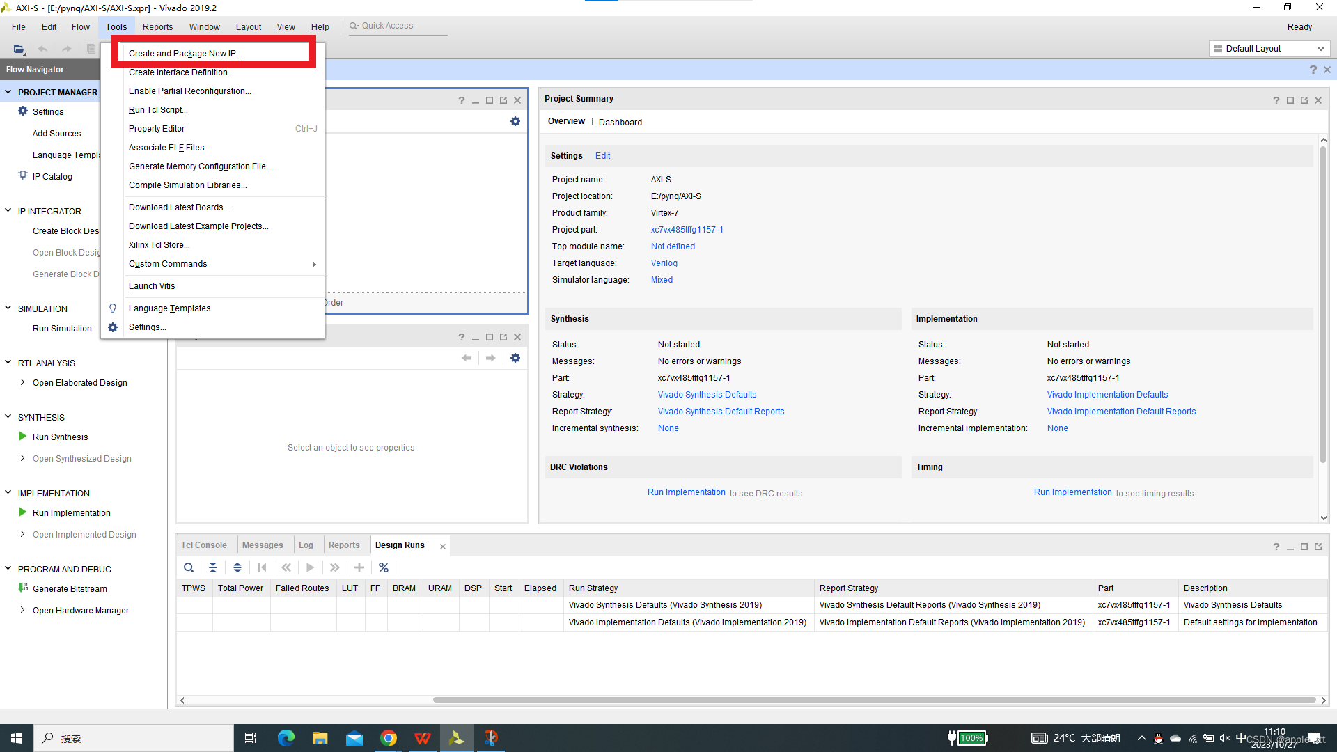
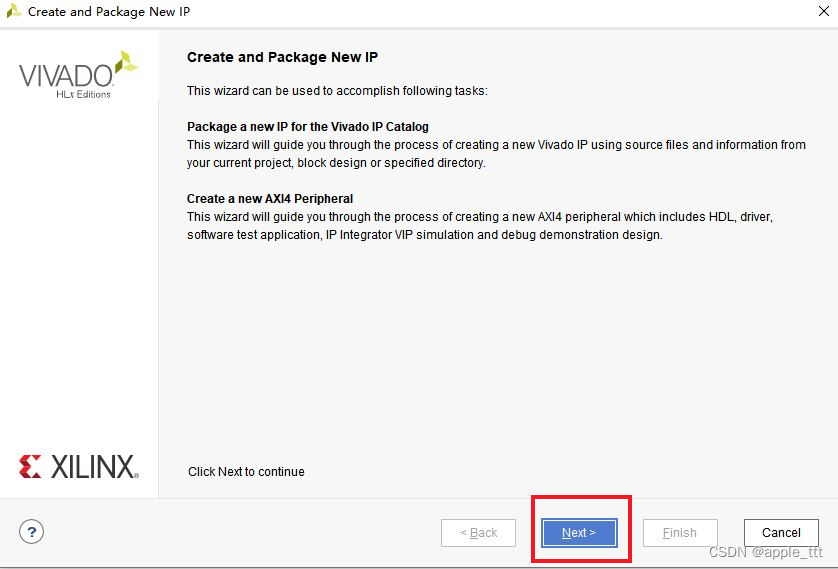
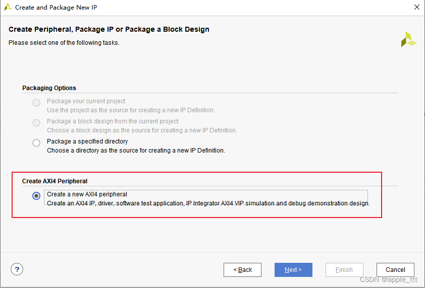
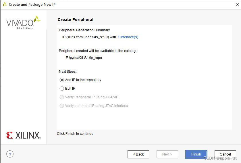
在这里我们选择最底下的一项,创建一个带有AXI接口的IP核
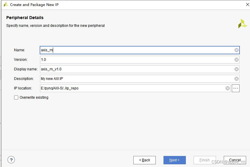
接下来我们设置IP核的一些细节信息,这里把名称改成了axis_m,代表这是AXI-Stream协议的主机。
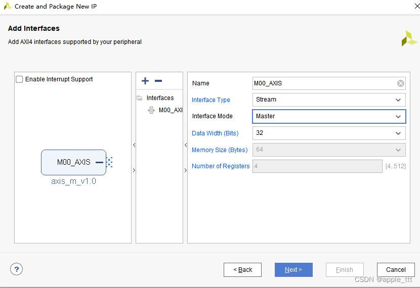
选择stream协议,选择主机类型,相应地完成名称更改,这里的数据位宽我们暂时不做更改,保持默认的32bit就行。
最后这里直接添加到IP库里就完成了。
然后我们通过同样的方式可以完成axi_s(带有AXI-S接口的从机)的创建,这里就省略创建过程了。
2、IP核学习
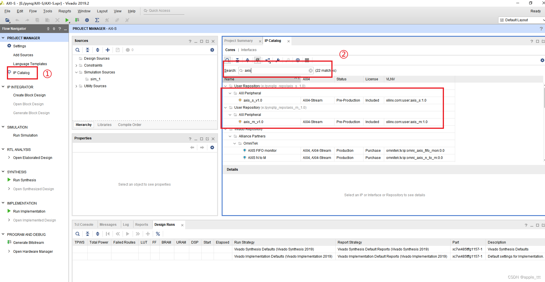
在IP Catlog下搜索找到我们之前创建的2个带有AXI-Stream协议的IP核
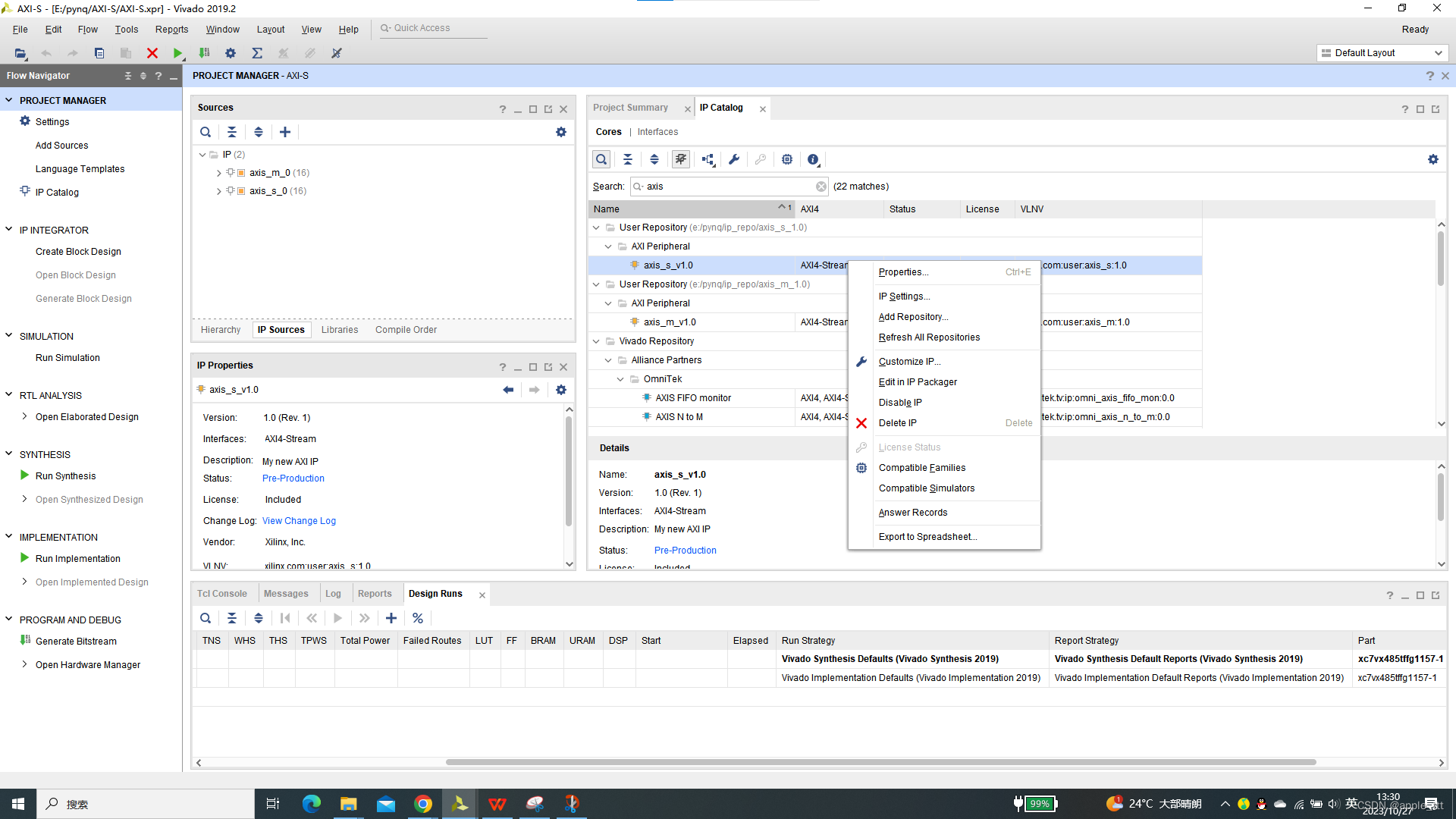
右击选择Edit in packager
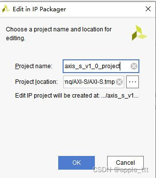
我们先以从机为例,显示如何找到AXI-S的设计部分,直接点击OK直到打开一个新的vivado界面
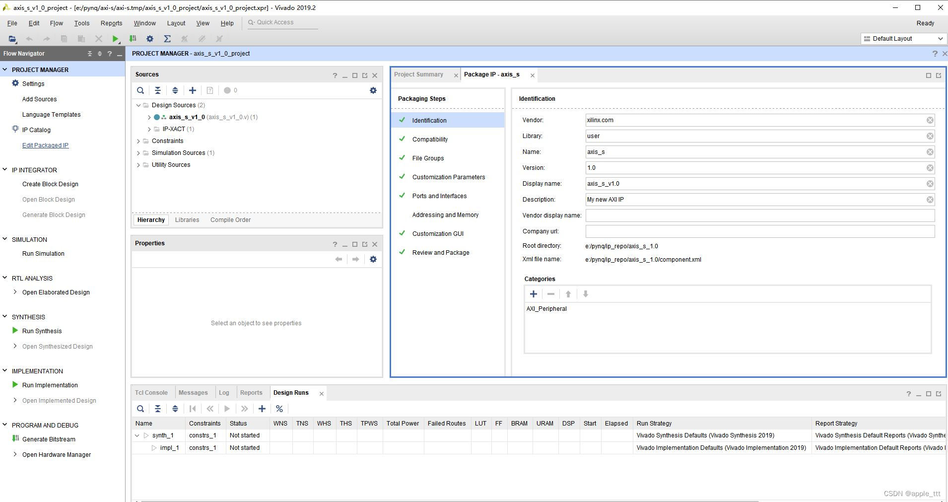
可以看到里面有两个模块
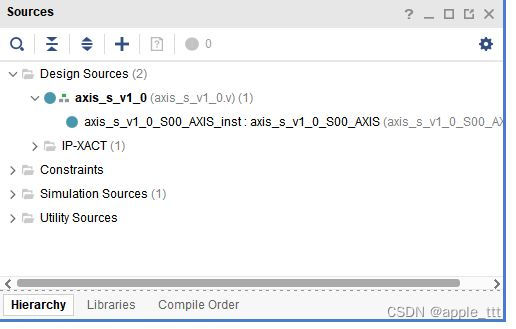
我们依次打开两个文件,同时可以把axis_m IP核中的文件同时打开,方便我们进行学习,打开过程同上,这里不做重复。
对于axis_s_v1_0和axis_m_v1_0这两个模块来说,只是完成了对底层模块的一个例化,所以没有什么可以过多赘述的。
下面我们着重介绍axis_s_v1_0_S00_AXIS和axis_m_v1_0_M00_AXIS两个模块
三、AXI-Stream源代码学习
其实Xilinx官方已经给出了非常详细的英文注释,可以帮助我们快速了解整个AXI-S协议的实现方式,写的真的非常好。这里也只是在其基础上做一个简单的翻译和补充,首先给出笔者中文注释版本,再给出官方的注释版本,推荐阅读后者。
1、AXIS主机部分
1.1 中文注释
`timescale 1 ns / 1 ps

	module axis_m_v1_0_M00_AXIS #
	(
		/*
			用户可以在此自定义参数
		*/

		parameter integer C_M_AXIS_TDATA_WIDTH	= 32,      // 发送数据的位宽
		// 初始化的最大计数时钟(等待系统稳定的时间)
		parameter integer C_M_START_COUNT	= 32
	)
	(
		/*
			用户可以在此自定义端口
		*/

		//全局信号
		input wire  M_AXIS_ACLK,                    			     // 时钟信号
		input wire  M_AXIS_ARESETN,                   				 // 复位信号(低电平有效)

		output wire  M_AXIS_TVALID,                   				 //有效信号,代表主机已经准备好了
		output wire [C_M_AXIS_TDATA_WIDTH-1 : 0] M_AXIS_TDATA,       //数据信号
		output wire [(C_M_AXIS_TDATA_WIDTH/8)-1 : 0] M_AXIS_TSTRB,	 //数据修饰符,辨别字节类型
		output wire  M_AXIS_TLAST,                      		     //last信号,拉高代表是传输中的最后一个字节
		input wire  M_AXIS_TREADY                                    //ready信号,代表从机准备好了
	);

	localparam NUMBER_OF_OUTPUT_WORDS = 8;                           //发送数据的个数

	//函数:以2为低求对数,用于计算位宽
	function integer clogb2 (input integer bit_depth);
	  begin
	    for(clogb2=0; bit_depth>0; clogb2=clogb2+1)
	      bit_depth = bit_depth >> 1;
	  end
	endfunction

	localparam integer WAIT_COUNT_BITS = clogb2(C_M_START_COUNT-1);  //等待计时寄存器的位宽
	localparam bit_num  = clogb2(NUMBER_OF_OUTPUT_WORDS);            //发送数据寄存器位宽

	//状态机参数
	parameter [1:0] IDLE = 2'b00,         						     //初始状态
	                INIT_COUNTER  = 2'b01,                           //初始化计数器,等待计数值达到最大计数时钟,进入下一个状态
	                SEND_STREAM   = 2'b10;                           //数据发送状态

	reg [1:0] mst_exec_state;                                        //状态寄存器
	reg [bit_num-1:0] read_pointer;                                  //FIFO读指针

	// AXIS内部信号
	reg [WAIT_COUNT_BITS-1 : 0] 	count;                           //等待计数器(实现我们之前说的计时功能)
	wire  	axis_tvalid;                                             //valid
	reg  	axis_tvalid_delay;                                       //延时一个时钟周期的valid
	wire  	axis_tlast;                                              //last
	reg  	axis_tlast_delay;                                        //延迟一个时钟周期的last

	reg [C_M_AXIS_TDATA_WIDTH-1 : 0] 	stream_data_out;             //data
	wire  	tx_en;                                                   //发送使能
	reg  	tx_done;                                                 //发送完成


	//赋值操作
	assign M_AXIS_TVALID	= axis_tvalid_delay;
	assign M_AXIS_TDATA	= stream_data_out;
	assign M_AXIS_TLAST	= axis_tlast_delay;
	assign M_AXIS_TSTRB	= {(C_M_AXIS_TDATA_WIDTH/8){1'b1}};         //全1


	//控制状态机
	always @(posedge M_AXIS_ACLK)
	begin
	  if (!M_AXIS_ARESETN)
	    begin
	      mst_exec_state <= IDLE;
	      count    <= 0;
	    end
	  else
	    case (mst_exec_state)
	      IDLE:                                             //一个周期后直接进入下一个状态
	            mst_exec_state  <= INIT_COUNTER;
	      INIT_COUNTER:                                     //计数器达到最大计数值,进入次态
	        if ( count == C_M_START_COUNT - 1 )
	          begin
	            mst_exec_state  <= SEND_STREAM;
	          end
	        else
	          begin
	            count <= count + 1;
	            mst_exec_state  <= INIT_COUNTER;
	          end

	      SEND_STREAM:                                    //发送状态,完成发送后回到初始态
	        if (tx_done)
	          begin
	            mst_exec_state <= IDLE;
	          end
	        else
	          begin
	            mst_exec_state <= SEND_STREAM;
	          end
	    endcase
	end

	//valid信号(表示主机有没有准备好),当处于发送状态,读指针小于发送数据个数时(也就是处于发送状态且还有数据要发)生效
	assign axis_tvalid = ((mst_exec_state == SEND_STREAM) && (read_pointer < NUMBER_OF_OUTPUT_WORDS));

	//last信号(表示发送的最后一个字节),当读指针等于发送数据个数-1时生效
	assign axis_tlast = (read_pointer == NUMBER_OF_OUTPUT_WORDS-1);

	//完成axis_tvalid_delay,axis_tlast_delay(延迟一个时钟的valid和last)的赋值
	always @(posedge M_AXIS_ACLK)
	begin
	  if (!M_AXIS_ARESETN)
	    begin
	      axis_tvalid_delay <= 1'b0;
	      axis_tlast_delay <= 1'b0;
	    end
	  else
	    begin
	      axis_tvalid_delay <= axis_tvalid;
	      axis_tlast_delay <= axis_tlast;
	    end
	end

	//读指针
	always@(posedge M_AXIS_ACLK)
	begin
	  if(!M_AXIS_ARESETN)                                //复位
	    begin
	      read_pointer <= 0;
	      tx_done <= 1'b0;
	    end
	  else
	    if (read_pointer <= NUMBER_OF_OUTPUT_WORDS-1)    //读指针小于等于发送数据个数-1,如果tx_en(发送使能),读指针递增,发送完成信号为0
	      begin
	        if (tx_en)
	          begin
	            read_pointer <= read_pointer + 1;
	            tx_done <= 1'b0;
	          end
	      end
	    else if (read_pointer == NUMBER_OF_OUTPUT_WORDS)
	      begin
	        tx_done <= 1'b1;                             //如果读指针等于发送数据个数,完成信号为1
	      end
	end

	assign tx_en = M_AXIS_TREADY && axis_tvalid;      	//读使能信号(从机+主机准备好)

	    //生成数据输出
	    always @( posedge M_AXIS_ACLK )
	    begin
	      if(!M_AXIS_ARESETN)
	        begin
	          stream_data_out <= 1;
	        end
	      else if (tx_en)
	        begin
	          stream_data_out <= read_pointer + 32'b1;   //定义数据为指针+1
	        end
	    end

	/*
		实现用户逻辑
	*/

	endmodule
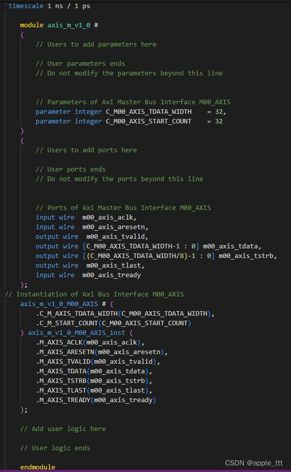
1.2 源码展示
`timescale 1 ns / 1 ps

	module axis_m_v1_0_M00_AXIS #
	(
		// Users to add parameters here

		// User parameters ends
		// Do not modify the parameters beyond this line

		// Width of S_AXIS address bus. The slave accepts the read and write addresses of width C_M_AXIS_TDATA_WIDTH.
		parameter integer C_M_AXIS_TDATA_WIDTH	= 32,
		// Start count is the number of clock cycles the master will wait before initiating/issuing any transaction.
		parameter integer C_M_START_COUNT	= 32
	)
	(
		// Users to add ports here

		// User ports ends
		// Do not modify the ports beyond this line

		// Global ports
		input wire  M_AXIS_ACLK,
		//
		input wire  M_AXIS_ARESETN,
		// Master Stream Ports. TVALID indicates that the master is driving a valid transfer, A transfer takes place when both TVALID and TREADY are asserted.
		output wire  M_AXIS_TVALID,
		// TDATA is the primary payload that is used to provide the data that is passing across the interface from the master.
		output wire [C_M_AXIS_TDATA_WIDTH-1 : 0] M_AXIS_TDATA,
		// TSTRB is the byte qualifier that indicates whether the content of the associated byte of TDATA is processed as a data byte or a position byte.
		output wire [(C_M_AXIS_TDATA_WIDTH/8)-1 : 0] M_AXIS_TSTRB,
		// TLAST indicates the boundary of a packet.
		output wire  M_AXIS_TLAST,
		// TREADY indicates that the slave can accept a transfer in the current cycle.
		input wire  M_AXIS_TREADY
	);
	// Total number of output data
	localparam NUMBER_OF_OUTPUT_WORDS = 8;

	// function called clogb2 that returns an integer which has the
	// value of the ceiling of the log base 2.
	function integer clogb2 (input integer bit_depth);
	  begin
	    for(clogb2=0; bit_depth>0; clogb2=clogb2+1)
	      bit_depth = bit_depth >> 1;
	  end
	endfunction

	// WAIT_COUNT_BITS is the width of the wait counter.
	localparam integer WAIT_COUNT_BITS = clogb2(C_M_START_COUNT-1);

	// bit_num gives the minimum number of bits needed to address 'depth' size of FIFO.
	localparam bit_num  = clogb2(NUMBER_OF_OUTPUT_WORDS);

	// Define the states of state machine
	// The control state machine oversees the writing of input streaming data to the FIFO,
	// and outputs the streaming data from the FIFO
	parameter [1:0] IDLE = 2'b00,        // This is the initial/idle state

	                INIT_COUNTER  = 2'b01, // This state initializes the counter, once
	                                // the counter reaches C_M_START_COUNT count,
	                                // the state machine changes state to SEND_STREAM
	                SEND_STREAM   = 2'b10; // In this state the
	                                     // stream data is output through M_AXIS_TDATA
	// State variable
	reg [1:0] mst_exec_state;
	// Example design FIFO read pointer
	reg [bit_num-1:0] read_pointer;

	// AXI Stream internal signals
	//wait counter. The master waits for the user defined number of clock cycles before initiating a transfer.
	reg [WAIT_COUNT_BITS-1 : 0] 	count;
	//streaming data valid
	wire  	axis_tvalid;
	//streaming data valid delayed by one clock cycle
	reg  	axis_tvalid_delay;
	//Last of the streaming data
	wire  	axis_tlast;
	//Last of the streaming data delayed by one clock cycle
	reg  	axis_tlast_delay;
	//FIFO implementation signals
	reg [C_M_AXIS_TDATA_WIDTH-1 : 0] 	stream_data_out;
	wire  	tx_en;
	//The master has issued all the streaming data stored in FIFO
	reg  	tx_done;


	// I/O Connections assignments

	assign M_AXIS_TVALID	= axis_tvalid_delay;
	assign M_AXIS_TDATA	= stream_data_out;
	assign M_AXIS_TLAST	= axis_tlast_delay;
	assign M_AXIS_TSTRB	= {(C_M_AXIS_TDATA_WIDTH/8){1'b1}};


	// Control state machine implementation
	always @(posedge M_AXIS_ACLK)
	begin
	  if (!M_AXIS_ARESETN)
	  // Synchronous reset (active low)
	    begin
	      mst_exec_state <= IDLE;
	      count    <= 0;
	    end
	  else
	    case (mst_exec_state)
	      IDLE:
	        // The slave starts accepting tdata when
	        // there tvalid is asserted to mark the
	        // presence of valid streaming data
	        //if ( count == 0 )
	        //  begin
	            mst_exec_state  <= INIT_COUNTER;
	        //  end
	        //else
	        //  begin
	        //    mst_exec_state  <= IDLE;
	        //  end

	      INIT_COUNTER:
	        // The slave starts accepting tdata when
	        // there tvalid is asserted to mark the
	        // presence of valid streaming data
	        if ( count == C_M_START_COUNT - 1 )
	          begin
	            mst_exec_state  <= SEND_STREAM;
	          end
	        else
	          begin
	            count <= count + 1;
	            mst_exec_state  <= INIT_COUNTER;
	          end

	      SEND_STREAM:
	        // The example design streaming master functionality starts
	        // when the master drives output tdata from the FIFO and the slave
	        // has finished storing the S_AXIS_TDATA
	        if (tx_done)
	          begin
	            mst_exec_state <= IDLE;
	          end
	        else
	          begin
	            mst_exec_state <= SEND_STREAM;
	          end
	    endcase
	end


	//tvalid generation
	//axis_tvalid is asserted when the control state machine's state is SEND_STREAM and
	//number of output streaming data is less than the NUMBER_OF_OUTPUT_WORDS.
	assign axis_tvalid = ((mst_exec_state == SEND_STREAM) && (read_pointer < NUMBER_OF_OUTPUT_WORDS));

	// AXI tlast generation
	// axis_tlast is asserted number of output streaming data is NUMBER_OF_OUTPUT_WORDS-1
	// (0 to NUMBER_OF_OUTPUT_WORDS-1)
	assign axis_tlast = (read_pointer == NUMBER_OF_OUTPUT_WORDS-1);


	// Delay the axis_tvalid and axis_tlast signal by one clock cycle
	// to match the latency of M_AXIS_TDATA
	always @(posedge M_AXIS_ACLK)
	begin
	  if (!M_AXIS_ARESETN)
	    begin
	      axis_tvalid_delay <= 1'b0;
	      axis_tlast_delay <= 1'b0;
	    end
	  else
	    begin
	      axis_tvalid_delay <= axis_tvalid;
	      axis_tlast_delay <= axis_tlast;
	    end
	end


	//read_pointer pointer

	always@(posedge M_AXIS_ACLK)
	begin
	  if(!M_AXIS_ARESETN)
	    begin
	      read_pointer <= 0;
	      tx_done <= 1'b0;
	    end
	  else
	    if (read_pointer <= NUMBER_OF_OUTPUT_WORDS-1)
	      begin
	        if (tx_en)
	          // read pointer is incremented after every read from the FIFO
	          // when FIFO read signal is enabled.
	          begin
	            read_pointer <= read_pointer + 1;
	            tx_done <= 1'b0;
	          end
	      end
	    else if (read_pointer == NUMBER_OF_OUTPUT_WORDS)
	      begin
	        // tx_done is asserted when NUMBER_OF_OUTPUT_WORDS numbers of streaming data
	        // has been out.
	        tx_done <= 1'b1;
	      end
	end


	//FIFO read enable generation

	assign tx_en = M_AXIS_TREADY && axis_tvalid;

	    // Streaming output data is read from FIFO
	    always @( posedge M_AXIS_ACLK )
	    begin
	      if(!M_AXIS_ARESETN)
	        begin
	          stream_data_out <= 1;
	        end
	      else if (tx_en)// && M_AXIS_TSTRB[byte_index]
	        begin
	          stream_data_out <= read_pointer + 32'b1;
	        end
	    end

	// Add user logic here

	// User logic ends

	endmodule
2、AXIS从机部分
1.1 中文注释
`timescale 1 ns / 1 ps

	module axis_s_v1_0_S00_AXIS #
	(
		/*
			用户可以自定义参数
		*/

		//AXIS数据位宽
		parameter integer C_S_AXIS_TDATA_WIDTH	= 32
	)
	(
		/*
			用户可以在此自定义端口
		*/

		input wire  S_AXIS_ACLK,                    			  //时钟信号
		input wire  S_AXIS_ARESETN,               			      //复位信号
		output wire  S_AXIS_TREADY,              			      //ready信号,代表从机准备好了
		input wire [C_S_AXIS_TDATA_WIDTH-1 : 0] S_AXIS_TDATA,     //数据信号
		input wire [(C_S_AXIS_TDATA_WIDTH/8)-1 : 0] S_AXIS_TSTRB, //数据修饰符,辨别字节类型
		input wire  S_AXIS_TLAST,								  //last信号,拉高代表是传输中的最后一个字节
		input wire  S_AXIS_TVALID                                 //ready信号,代表从机准备好了
	);

	//函数:以2为低求对数,用于计算位宽
	function integer clogb2 (input integer bit_depth);
	  begin
	    for(clogb2=0; bit_depth>0; clogb2=clogb2+1)
	      bit_depth = bit_depth >> 1;
	  end
	endfunction

	localparam NUMBER_OF_INPUT_WORDS  = 8;                      //输入数据个数
	localparam bit_num  = clogb2(NUMBER_OF_INPUT_WORDS-1);      //输入数据的位宽

	//状态机定义
	parameter [1:0] IDLE = 1'b0,                                //初始状态
	                WRITE_FIFO  = 1'b1;                         //读状态

	wire  	axis_tready;                                        //ready信号

	reg mst_exec_state;                                         //状态寄存器

	genvar byte_index;                                          //字节索引

	wire fifo_wren;                                             //FIFO写使能
	reg fifo_full_flag;                                         //FIFO满标志
	reg [bit_num-1:0] write_pointer;                            //FIFO写指针
	reg writes_done;                                            //写满标志

	assign S_AXIS_TREADY	= axis_tready;

	//状态机
	always @(posedge S_AXIS_ACLK)
	begin
	  if (!S_AXIS_ARESETN)
	    begin
	      mst_exec_state <= IDLE;
	    end
	  else
	    case (mst_exec_state)
	      IDLE:
	          if (S_AXIS_TVALID)
	            begin
	              mst_exec_state <= WRITE_FIFO;
	            end
	          else
	            begin
	              mst_exec_state <= IDLE;
	            end
	      WRITE_FIFO:
	        if (writes_done)
	          begin
	            mst_exec_state <= IDLE;
	          end
	        else
	          begin
	            mst_exec_state <= WRITE_FIFO;
	          end

	    endcase
	end

	//ready信号赋值,写状态+读指针写于等于接收数据总个数
	assign axis_tready = ((mst_exec_state == WRITE_FIFO) && (write_pointer <= NUMBER_OF_INPUT_WORDS-1));

	//写指针,写完成信号
	always@(posedge S_AXIS_ACLK)
	begin
	  if(!S_AXIS_ARESETN)
	    begin
	      write_pointer <= 0;
	      writes_done <= 1'b0;
	    end
	  else
	    if (write_pointer <= NUMBER_OF_INPUT_WORDS-1)
	      begin
	        if (fifo_wren)
	          begin
	            write_pointer <= write_pointer + 1;
	            writes_done <= 1'b0;
	          end
	          if ((write_pointer == NUMBER_OF_INPUT_WORDS-1)|| S_AXIS_TLAST)
	            begin
	              writes_done <= 1'b1;
	            end
	      end
	end

	//FIFO写使能信号
	assign fifo_wren = S_AXIS_TVALID && axis_tready;

	//例化4个宽为8,深度为8的二维数组stream_data_fifo,用来充当FIFO,每个FIFO依次写入数据的0-7;8-15;16-23;24-31位
	generate
	  for(byte_index=0; byte_index<= (C_S_AXIS_TDATA_WIDTH/8-1); byte_index=byte_index+1)
	  begin:FIFO_GEN

	    reg  [(C_S_AXIS_TDATA_WIDTH/4)-1:0] stream_data_fifo [0 : NUMBER_OF_INPUT_WORDS-1];

		//写入FIFO数据
	    always @( posedge S_AXIS_ACLK )
	    begin
	      if (fifo_wren)// && S_AXIS_TSTRB[byte_index])
	        begin
	          stream_data_fifo[write_pointer] <= S_AXIS_TDATA[(byte_index*8+7) -: 8];
	        end
	    end
	  end
	endgenerate

	/*
		实现用户逻辑
	*/

	endmodule
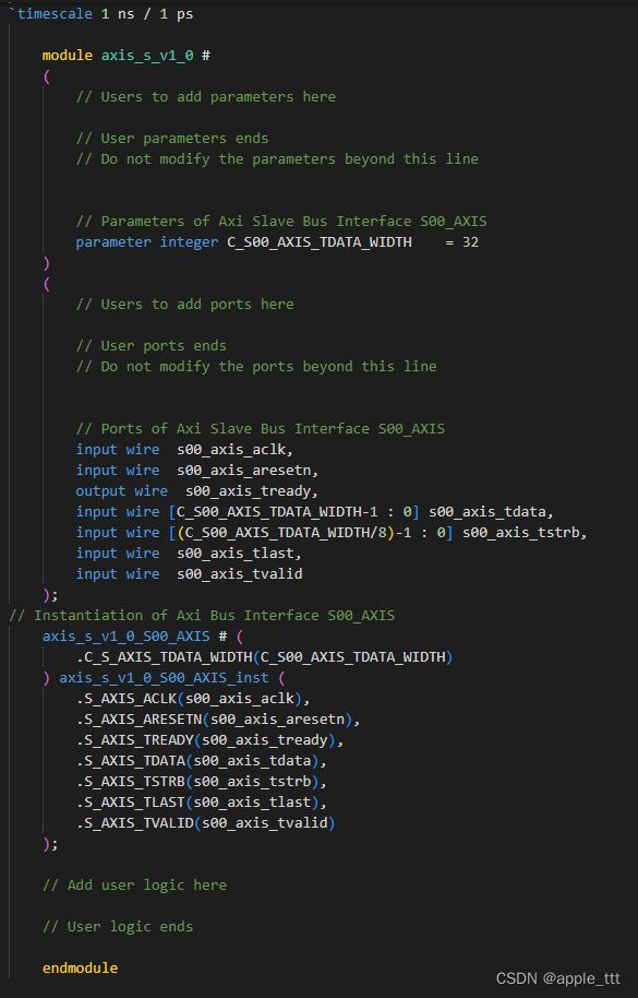
1.2 源码展示
`timescale 1 ns / 1 ps

	module axis_s_v1_0_S00_AXIS #
	(
		// Users to add parameters here

		// User parameters ends
		// Do not modify the parameters beyond this line

		// AXI4Stream sink: Data Width
		parameter integer C_S_AXIS_TDATA_WIDTH	= 32
	)
	(
		// Users to add ports here

		// User ports ends
		// Do not modify the ports beyond this line

		// AXI4Stream sink: Clock
		input wire  S_AXIS_ACLK,
		// AXI4Stream sink: Reset
		input wire  S_AXIS_ARESETN,
		// Ready to accept data in
		output wire  S_AXIS_TREADY,
		// Data in
		input wire [C_S_AXIS_TDATA_WIDTH-1 : 0] S_AXIS_TDATA,
		// Byte qualifier
		input wire [(C_S_AXIS_TDATA_WIDTH/8)-1 : 0] S_AXIS_TSTRB,
		// Indicates boundary of last packet
		input wire  S_AXIS_TLAST,
		// Data is in valid
		input wire  S_AXIS_TVALID
	);
	// function called clogb2 that returns an integer which has the
	// value of the ceiling of the log base 2.
	function integer clogb2 (input integer bit_depth);
	  begin
	    for(clogb2=0; bit_depth>0; clogb2=clogb2+1)
	      bit_depth = bit_depth >> 1;
	  end
	endfunction

	// Total number of input data.
	localparam NUMBER_OF_INPUT_WORDS  = 8;
	// bit_num gives the minimum number of bits needed to address 'NUMBER_OF_INPUT_WORDS' size of FIFO.
	localparam bit_num  = clogb2(NUMBER_OF_INPUT_WORDS-1);
	// Define the states of state machine
	// The control state machine oversees the writing of input streaming data to the FIFO,
	// and outputs the streaming data from the FIFO
	parameter [1:0] IDLE = 1'b0,        // This is the initial/idle state

	                WRITE_FIFO  = 1'b1; // In this state FIFO is written with the
	                                    // input stream data S_AXIS_TDATA
	wire  	axis_tready;
	// State variable
	reg mst_exec_state;
	// FIFO implementation signals
	genvar byte_index;
	// FIFO write enable
	wire fifo_wren;
	// FIFO full flag
	reg fifo_full_flag;
	// FIFO write pointer
	reg [bit_num-1:0] write_pointer;
	// sink has accepted all the streaming data and stored in FIFO
	  reg writes_done;
	// I/O Connections assignments

	assign S_AXIS_TREADY	= axis_tready;
	// Control state machine implementation
	always @(posedge S_AXIS_ACLK)
	begin
	  if (!S_AXIS_ARESETN)
	  // Synchronous reset (active low)
	    begin
	      mst_exec_state <= IDLE;
	    end
	  else
	    case (mst_exec_state)
	      IDLE:
	        // The sink starts accepting tdata when
	        // there tvalid is asserted to mark the
	        // presence of valid streaming data
	          if (S_AXIS_TVALID)
	            begin
	              mst_exec_state <= WRITE_FIFO;
	            end
	          else
	            begin
	              mst_exec_state <= IDLE;
	            end
	      WRITE_FIFO:
	        // When the sink has accepted all the streaming input data,
	        // the interface swiches functionality to a streaming master
	        if (writes_done)
	          begin
	            mst_exec_state <= IDLE;
	          end
	        else
	          begin
	            // The sink accepts and stores tdata
	            // into FIFO
	            mst_exec_state <= WRITE_FIFO;
	          end

	    endcase
	end
	// AXI Streaming Sink
	//
	// The example design sink is always ready to accept the S_AXIS_TDATA  until
	// the FIFO is not filled with NUMBER_OF_INPUT_WORDS number of input words.
	assign axis_tready = ((mst_exec_state == WRITE_FIFO) && (write_pointer <= NUMBER_OF_INPUT_WORDS-1));

	always@(posedge S_AXIS_ACLK)
	begin
	  if(!S_AXIS_ARESETN)
	    begin
	      write_pointer <= 0;
	      writes_done <= 1'b0;
	    end
	  else
	    if (write_pointer <= NUMBER_OF_INPUT_WORDS-1)
	      begin
	        if (fifo_wren)
	          begin
	            // write pointer is incremented after every write to the FIFO
	            // when FIFO write signal is enabled.
	            write_pointer <= write_pointer + 1;
	            writes_done <= 1'b0;
	          end
	          if ((write_pointer == NUMBER_OF_INPUT_WORDS-1)|| S_AXIS_TLAST)
	            begin
	              // reads_done is asserted when NUMBER_OF_INPUT_WORDS numbers of streaming data
	              // has been written to the FIFO which is also marked by S_AXIS_TLAST(kept for optional usage).
	              writes_done <= 1'b1;
	            end
	      end
	end

	// FIFO write enable generation
	assign fifo_wren = S_AXIS_TVALID && axis_tready;

	// FIFO Implementation
	generate
	  for(byte_index=0; byte_index<= (C_S_AXIS_TDATA_WIDTH/8-1); byte_index=byte_index+1)
	  begin:FIFO_GEN

	    reg  [(C_S_AXIS_TDATA_WIDTH/4)-1:0] stream_data_fifo [0 : NUMBER_OF_INPUT_WORDS-1];

	    // Streaming input data is stored in FIFO

	    always @( posedge S_AXIS_ACLK )
	    begin
	      if (fifo_wren)// && S_AXIS_TSTRB[byte_index])
	        begin
	          stream_data_fifo[write_pointer] <= S_AXIS_TDATA[(byte_index*8+7) -: 8];
	        end
	    end
	  end
	endgenerate

	// Add user logic here

	// User logic ends

	endmodule
四、仿真测试
1、top
module top(
    input clk,
    input rst_n
    );

    wire [31:0] axis_tdata;
    wire [3:0]  axis_tstrb;
    wire        axis_tlast;
    wire        axis_tready;
    wire        axis_tvalid;

    axis_m_0 axis_m_u0
    (
     .m00_axis_tdata      (axis_tdata),
     .m00_axis_tstrb      (axis_tstrb),
     .m00_axis_tlast      (axis_tlast),
     .m00_axis_tvalid     (axis_tvalid),
     .m00_axis_tready     (axis_tready),
     .m00_axis_aclk       (clk),
     .m00_axis_aresetn    (rst_n)
    );

    axis_s_0 axis_s_u0
    (
     .s00_axis_tdata      (axis_tdata),
     .s00_axis_tstrb      (axis_tstrb),
     .s00_axis_tlast      (axis_tlast),
     .s00_axis_tvalid     (axis_tvalid),
     .s00_axis_tready     (axis_tready),
     .s00_axis_aclk       (clk),
     .s00_axis_aresetn    (rst_n)
    );

endmodule
2、tb
`timescale 1ns / 1ps

module tb_top();
    reg clk,rst_n;

initial begin
    clk = 0;
    rst_n = 1;
#10
    rst_n = 0;
#10
    rst_n = 1;
end

always #5 clk <= ~clk;

top top_u1(.clk(clk),
           .rst_n(rst_n));

endmodule
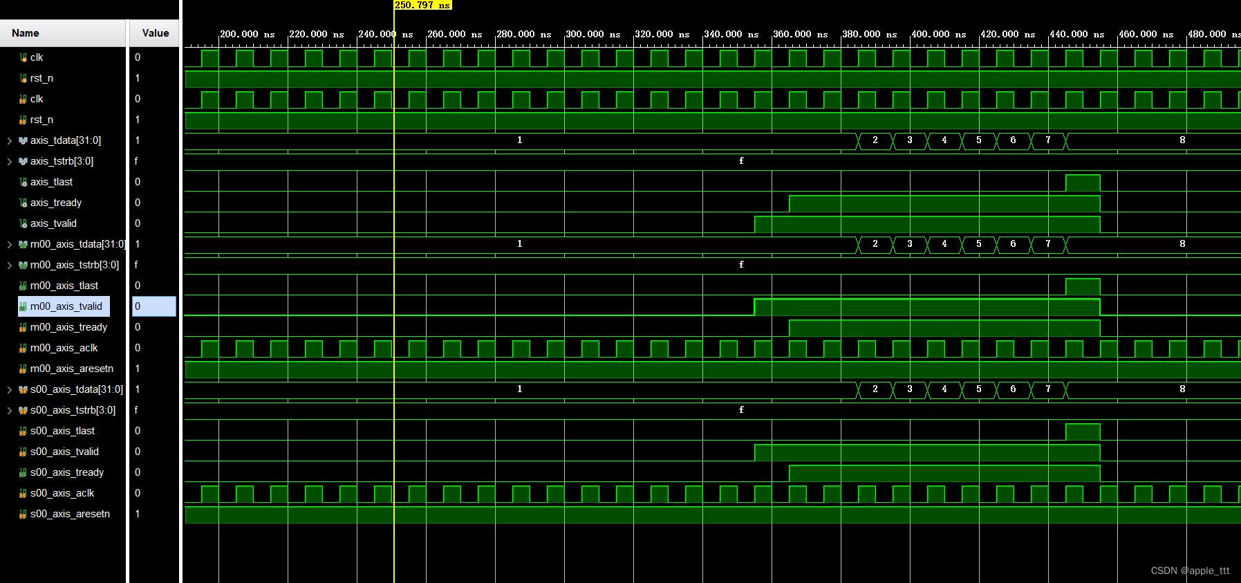
3、结果