https://gitee.com/linhir-linhir/stm32-f103-c8/blob/master/STM32%E6%9C%80%E6%96%B0%E5%9B%BA%E4%BB%B6%E5%BA%93v3.5/Libraries/STM32F10x_StdPeriph_Driver/inc/stm32f10x_rcc.h
STM32最新固件库v3.5/Libraries/CMSIS/CM3/DeviceSupport/ST/STM32F10x/system_stm32f10x.c · 林何/STM32F103C8 - 码云 - 开源中国 (gitee.com)
1.宏定义
1.宏定义的位置
如果这个宏定义只能在.c文件中使用,则应该在.c文件中定义
如果这个宏定义既可以在.c或者.h文件中使用,则应该在.h中定义
2.位带:RCC_OFFSET
因为我们STM32是32位的寄存器,所以如果我们只想要操作寄存器其中的一位,所以我们可以使用位移操作
/* ------------ RCC registers bit address in the alias region ----------- */
/*
RCC_OFFSET:等价于RCC的基地址和外设寄存器之差
*/
/*!< PERIPH_BAS--》 Peripheral base address in the alias region */
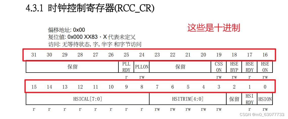
#define RCC_OFFSET (RCC_BASE - PERIPH_BASE)3.第一个寄存器:CR
1.HSION
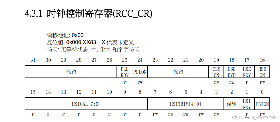
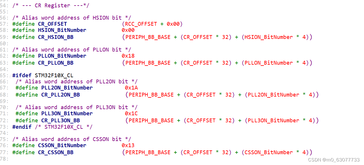
/* --- CR Register ---*/

/* Alias word address of HSION bit */
//这个寄存器相对于基地址的位置
#define CR_OFFSET                 (RCC_OFFSET + 0x00)
//操作HSION这一位相对于整个CR寄存器的偏移量
#define HSION_BitNumber           0x00
//CR寄存器中的HSION中的位带
//PERIPH_BB_BASE:位带访问区的基地址
#define CR_HSION_BB               (PERIPH_BB_BASE + (CR_OFFSET * 32) + (HSION_BitNumber * 4))
如果想要对其进行设置,就直接给CR_HSION_BB赋值
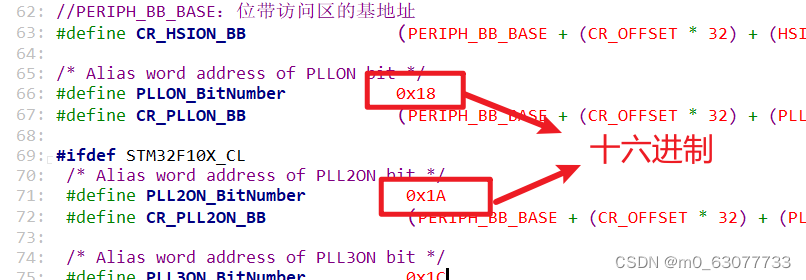
2.PLLON
/* Alias word address of PLLON bit */
#define PLLON_BitNumber           0x18
#define CR_PLLON_BB               (PERIPH_BB_BASE + (CR_OFFSET * 32) + (PLLON_BitNumber * 4))
4.RCC registers bit mask
Reset:进行位与置0
Set:进行位或置1
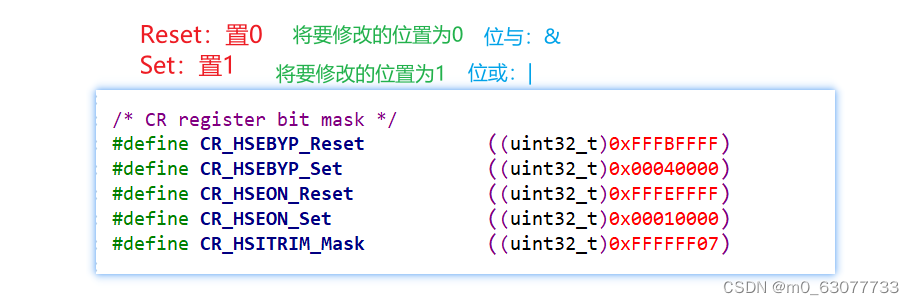
/* ---------------------- RCC registers bit mask ------------------------ */
/* CR register bit mask */
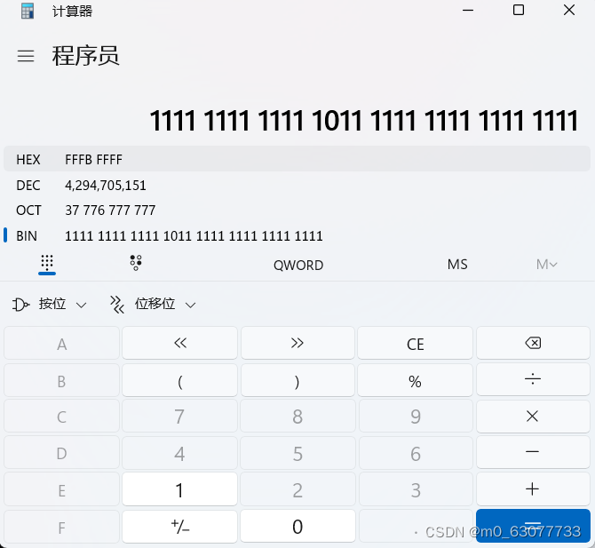
#define CR_HSEBYP_Reset ((uint32_t)0xFFFBFFFF)
#define CR_HSEBYP_Set ((uint32_t)0x00040000)
#define CR_HSEON_Reset ((uint32_t)0xFFFEFFFF)
#define CR_HSEON_Set ((uint32_t)0x00010000)
#define CR_HSITRIM_Mask ((uint32_t)0xFFFFFF07)
2.全局变量
定义了预分配处理器
1.static
c语言中static关键字用法详解_static在c语言中的用法-CSDN博客
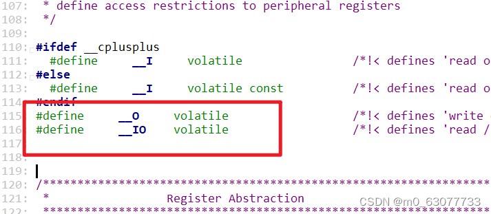
2.volatile
这个变量跟某一个寄存器的值进行绑定,寄存器里面有一个值是硬件可以改动的值
C语言丨深入理解volatile关键字-腾讯云开发者社区-腾讯云 (tencent.com)
3.uint
uint8:表示unsigned short
uint16:表示unsigned char
uint32:表示unsigned int
static __I uint8_t APBAHBPrescTable[16] = {0, 0, 0, 0, 1, 2, 3, 4, 1, 2, 3, 4, 6, 7, 8, 9};
static __I uint8_t ADCPrescTable[4] = {2, 4, 6, 8};
3.函数
1.RCC_DeInit
/**
  * @brief  Resets the RCC clock configuration to the default reset state.
  * @param  None
  * @retval None
  */
void RCC_DeInit(void)
{
  /* Set HSION bit */
//将CR这个位写为1
  RCC->CR |= (uint32_t)0x00000001;

  /* Reset SW, HPRE, PPRE1, PPRE2, ADCPRE and MCO bits */
#ifndef STM32F10X_CL
  RCC->CFGR &= (uint32_t)0xF8FF0000;
#else//非CL的芯片使用
  RCC->CFGR &= (uint32_t)0xF0FF0000;
#endif /* STM32F10X_CL */

  /* Reset HSEON, CSSON and PLLON bits */
//HSEON, CSSON and PLLON:将这几位置0
  RCC->CR &= (uint32_t)0xFEF6FFFF;

  /* Reset HSEBYP bit */
  RCC->CR &= (uint32_t)0xFFFBFFFF;

  /* Reset PLLSRC, PLLXTPRE, PLLMUL and USBPRE/OTGFSPRE bits */
  RCC->CFGR &= (uint32_t)0xFF80FFFF;

#ifdef STM32F10X_CL
  /* Reset PLL2ON and PLL3ON bits */
  RCC->CR &= (uint32_t)0xEBFFFFFF;

  /* Disable all interrupts and clear pending bits  */
  RCC->CIR = 0x00FF0000;

  /* Reset CFGR2 register */
  RCC->CFGR2 = 0x00000000;
#elif defined (STM32F10X_LD_VL) || defined (STM32F10X_MD_VL) || defined (STM32F10X_HD_VL)
  /* Disable all interrupts and clear pending bits  */
  RCC->CIR = 0x009F0000;

  /* Reset CFGR2 register */
  RCC->CFGR2 = 0x00000000;
#else
  /* Disable all interrupts and clear pending bits  */
  RCC->CIR = 0x009F0000;
#endif /* STM32F10X_CL */

}
2.RCC_HSEConfig
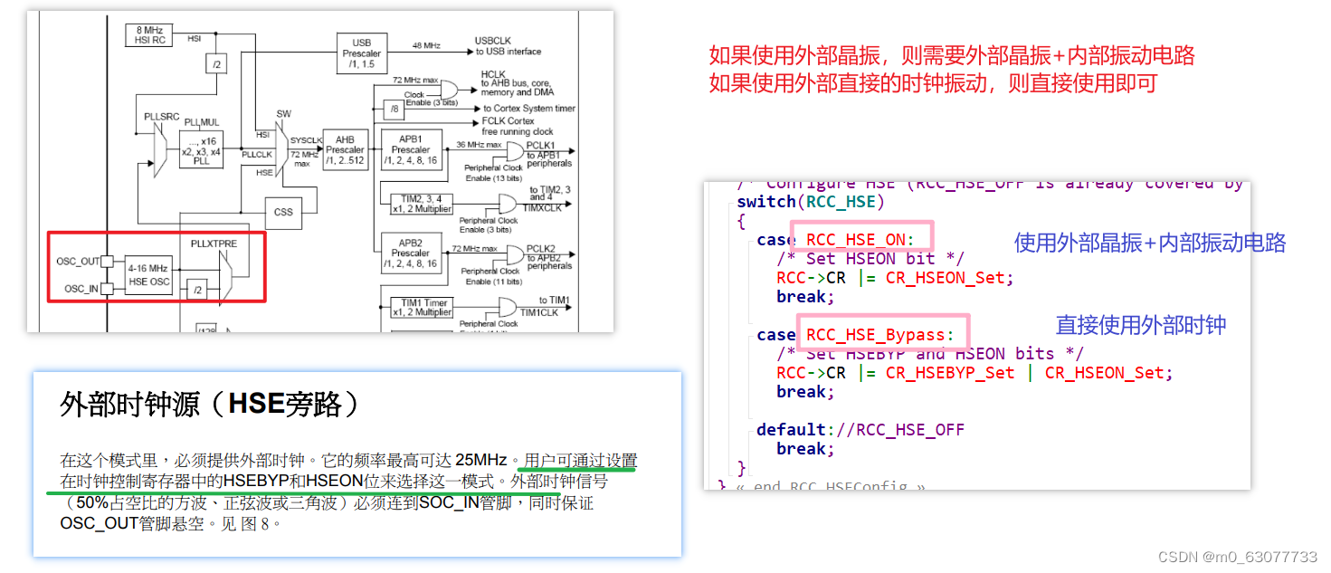
可以关闭时钟,所以平时我们不操纵它
这个HSEConfig实际效果:控制CPU是使用
外部晶振+内部振动电路 VS 外部时钟
1.assert:断言
assert机制是c语言用来判断一个东西是对的还是错的,如果是对的直接忽略过去,如果是错的就以某一种方式告诉我们(warrning error)让我们去修改。
/* Exported macro ------------------------------------------------------------*/
#ifdef  USE_FULL_ASSERT
/**
  * @brief  The assert_param macro is used for function's parameters check.
  * @param  expr: If expr is false, it calls assert_failed function which reports
  *         the name of the source file and the source line number of the call
  *         that failed. If expr is true, it returns no value.
  * @retval None
  */
  #define assert_param(expr) ((expr) ? (void)0 : assert_failed((uint8_t *)__FILE__, __LINE__))
/* Exported functions ------------------------------------------------------- */
  void assert_failed(uint8_t* file, uint32_t line);
#else
  #define assert_param(expr) ((void)0)
#endif /* USE_FULL_ASSERT */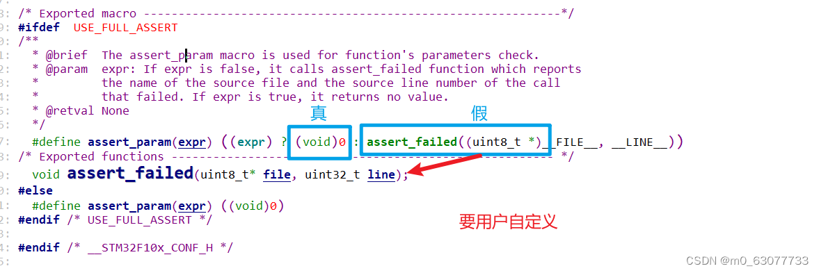
这个函数要用户自己去实现
void assert_failed(uint8_t* file, uint32_t line)
{
/* User can add his own implementation to report the file name and line number,
ex: printf("Wrong parameters value: file %s on line %d\r\n", file, line) */
/* Infinite loop */
//用户用自己的方法去报错一个断言错误
//用户可以用#error灯方法来在编译时报错(前提是断言表达式必须在预处理时就能有结果)
//更常见的方式是用户在运行时报错,用printf打印调试信息
//
while (1)
{
}
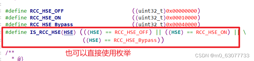
}2.判断用户输入的参数是否正确
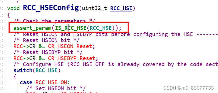
3.代码理解
/**
* @brief Configures the External High Speed oscillator (HSE).
* @note HSE can not be stopped if it is used directly or through the PLL as system clock.
* @param RCC_HSE: specifies the new state of the HSE.
* This parameter can be one of the following values:
* @arg RCC_HSE_OFF: HSE oscillator OFF
* @arg RCC_HSE_ON: HSE oscillator ON
* @arg RCC_HSE_Bypass: HSE oscillator bypassed with external clock
* @retval None
*/
void RCC_HSEConfig(uint32_t RCC_HSE)
{
/* Check the parameters */
assert_param(IS_RCC_HSE(RCC_HSE));
/* Reset HSEON and HSEBYP bits before configuring the HSE ------------------*/
/* Reset HSEON bit */
RCC->CR &= CR_HSEON_Reset;
/* Reset HSEBYP bit */
RCC->CR &= CR_HSEBYP_Reset;
/* Configure HSE (RCC_HSE_OFF is already covered by the code section above) */
switch(RCC_HSE)
{
case RCC_HSE_ON:
/* Set HSEON bit */
RCC->CR |= CR_HSEON_Set;
break;
case RCC_HSE_Bypass:
/* Set HSEBYP and HSEON bits */
RCC->CR |= CR_HSEBYP_Set | CR_HSEON_Set;
break;
default://RCC_HSE_OFF
break;
}
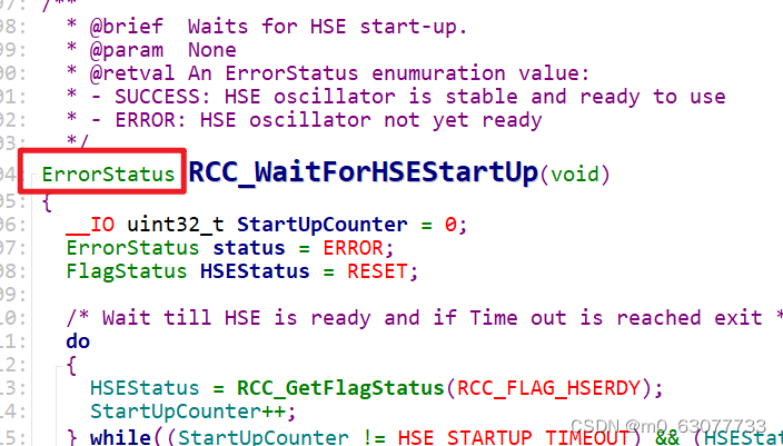
}3.RCC_WaitForHSEStartUp(等待HSE)
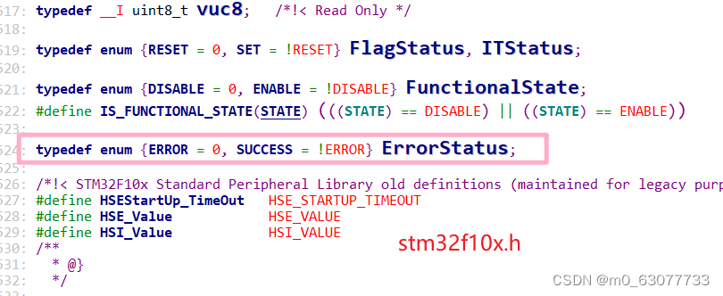
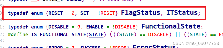
1.ErrorStatus
判断是否成功
一般:0:表示失败
1:表示成功
2.计数值加上volatile
因为这个变量是我们来进行判断是否超时的局部变量,所以每当我们调用这个函数的时候,应该将这个计数值清0,所以这里才使用
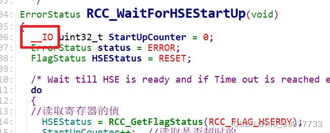
3.代码理解
/**
* @brief Waits for HSE start-up.
* @param None
* @retval An ErrorStatus enumuration value:
* - SUCCESS: HSE oscillator is stable and ready to use
* - ERROR: HSE oscillator not yet ready
*/
ErrorStatus RCC_WaitForHSEStartUp(void)
{
__IO uint32_t StartUpCounter = 0;
ErrorStatus status = ERROR;
FlagStatus HSEStatus = RESET;
/* Wait till HSE is ready and if Time out is reached exit */
do
{
//读取寄存器的值
HSEStatus = RCC_GetFlagStatus(RCC_FLAG_HSERDY);
StartUpCounter++; //读取是否超时的
} while((StartUpCounter != HSE_STARTUP_TIMEOUT) && (HSEStatus == RESET));
//这里判断是防止超时
if (RCC_GetFlagStatus(RCC_FLAG_HSERDY) != RESET)
{
status = SUCCESS;
}
else
{
//超时
status = ERROR;
}
return (status);
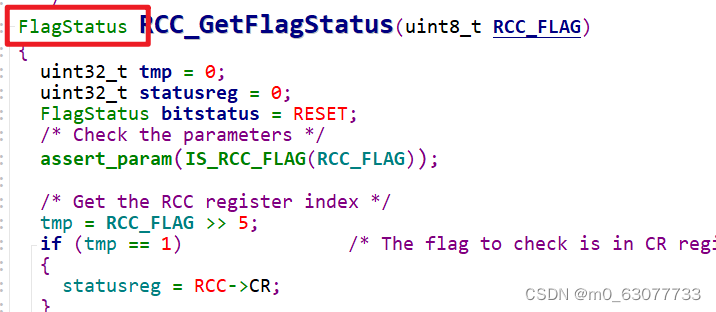
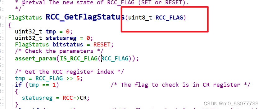
}4.RCC_GetFlagStatus(获取bit位状态)
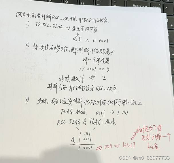
1)确定这个RCC-FLAG在哪一个寄存器上
2)确定这个RCC_FLAG在寄存器是哪一个位上
1.返回值进行状态判断
2.输入参数
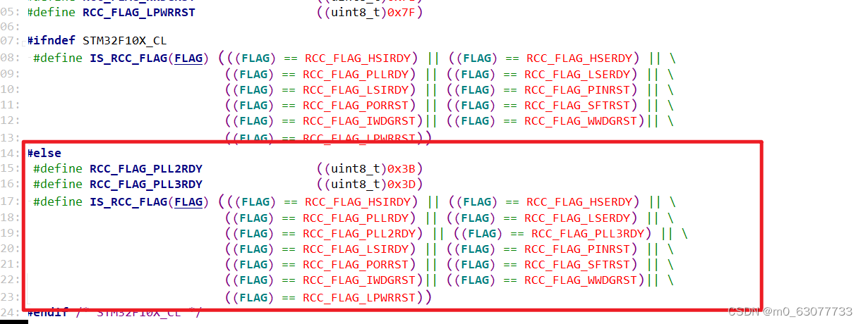
3.IS_RCC_FLAG
4.判断当前是在哪一个寄存器中
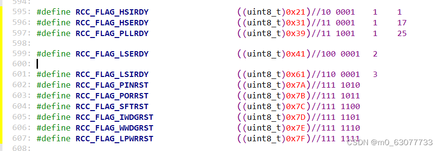
右移5位是想要判断第5位是1还是2还是3,然后进行判断是哪一个寄存器
  /* Get the RCC register index */
  //将输入的标志位右移5位
  tmp = RCC_FLAG >> 5;
  //判断要访问哪一个寄存器
  if (tmp == 1)               /* The flag to check is in CR register */
  {
    statusreg = RCC->CR;
  }
  else if (tmp == 2)          /* The flag to check is in BDCR register */
  {
    statusreg = RCC->BDCR;
  }
  else                       /* The flag to check is in CSR register */
  {
    statusreg = RCC->CSR;
  }
5.判断在寄存器的哪一个位上
  /* Get the flag position */
  /**
	FLAG_Mask:0x1f
  */
  tmp = RCC_FLAG & FLAG_Mask;
  if ((statusreg & ((uint32_t)1 << tmp)) != (uint32_t)RESET)
  {
    bitstatus = SET;
  }
  else
  {
    bitstatus = RESET;
  }
6.代码理解
/**
* @brief Checks whether the specified RCC flag is set or not.
* @param RCC_FLAG: specifies the flag to check.
*
* For @b STM32_Connectivity_line_devices, this parameter can be one of the
* following values:
* @arg RCC_FLAG_HSIRDY: HSI oscillator clock ready
* @arg RCC_FLAG_HSERDY: HSE oscillator clock ready
* @arg RCC_FLAG_PLLRDY: PLL clock ready
* @arg RCC_FLAG_PLL2RDY: PLL2 clock ready
* @arg RCC_FLAG_PLL3RDY: PLL3 clock ready
* @arg RCC_FLAG_LSERDY: LSE oscillator clock ready
* @arg RCC_FLAG_LSIRDY: LSI oscillator clock ready
* @arg RCC_FLAG_PINRST: Pin reset
* @arg RCC_FLAG_PORRST: POR/PDR reset
* @arg RCC_FLAG_SFTRST: Software reset
* @arg RCC_FLAG_IWDGRST: Independent Watchdog reset
* @arg RCC_FLAG_WWDGRST: Window Watchdog reset
* @arg RCC_FLAG_LPWRRST: Low Power reset
*
* For @b other_STM32_devices, this parameter can be one of the following values:
* @arg RCC_FLAG_HSIRDY: HSI oscillator clock ready
* @arg RCC_FLAG_HSERDY: HSE oscillator clock ready
* @arg RCC_FLAG_PLLRDY: PLL clock ready
* @arg RCC_FLAG_LSERDY: LSE oscillator clock ready
* @arg RCC_FLAG_LSIRDY: LSI oscillator clock ready
* @arg RCC_FLAG_PINRST: Pin reset
* @arg RCC_FLAG_PORRST: POR/PDR reset
* @arg RCC_FLAG_SFTRST: Software reset
* @arg RCC_FLAG_IWDGRST: Independent Watchdog reset
* @arg RCC_FLAG_WWDGRST: Window Watchdog reset
* @arg RCC_FLAG_LPWRRST: Low Power reset
*
* @retval The new state of RCC_FLAG (SET or RESET).
*/
FlagStatus RCC_GetFlagStatus(uint8_t RCC_FLAG)
{
uint32_t tmp = 0;
uint32_t statusreg = 0;
FlagStatus bitstatus = RESET;
/* Check the parameters */
assert_param(IS_RCC_FLAG(RCC_FLAG));
/* Get the RCC register index */
//将输入的标志位右移5位
tmp = RCC_FLAG >> 5;
//判断要访问哪一个寄存器
if (tmp == 1) /* The flag to check is in CR register */
{
statusreg = RCC->CR;
}
else if (tmp == 2) /* The flag to check is in BDCR register */
{
statusreg = RCC->BDCR;
}
else /* The flag to check is in CSR register */
{
statusreg = RCC->CSR;
}
/* Get the flag position */
/**
FLAG_Mask:0x1f:1 1111
*/
//这里我们可以得出应该将“1”移动几个bit
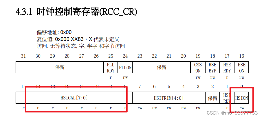
//比如我们此时选中的RCC_FLAG=RCC->CR的HSERDY(此位对应bit17)
//则此时tmp=11 0001 & 1 1111=1 0001(对应十进制17)
tmp = RCC_FLAG & FLAG_Mask;
//RESET表示置位:表示数值“0”
if ((statusreg & ((uint32_t)1 << tmp)) != (uint32_t)RESET)
{
//此时进入,表示该位已经被设置为1
bitstatus = SET;
}
else
{
bitstatus = RESET;
}
/* Return the flag status */
return bitstatus;
}
5.RCC_HSICmd(设置内部晶振状态)
发送命令的
/**
  * @brief  Enables or disables the Internal High Speed oscillator (HSI).
  * @note   HSI can not be stopped if it is used directly or through the PLL as system clock.
  * @param  NewState: new state of the HSI. This parameter can be: ENABLE or DISABLE.
  * @retval None
  */
void RCC_HSICmd(FunctionalState NewState)
{
  /* Check the parameters */
  assert_param(IS_FUNCTIONAL_STATE(NewState));
  *(__IO uint32_t *) CR_HSION_BB = (uint32_t)NewState;
}
这里使用解引用的方式,因为我们这里只需要操纵一位
6.RCC_PLLConfig(设置时钟频率)
在使用这个PLL之前一定一定是没有使用PLL,才可以调用这个函数
配置PLL的时钟源倍频
1.参数:时钟倍频
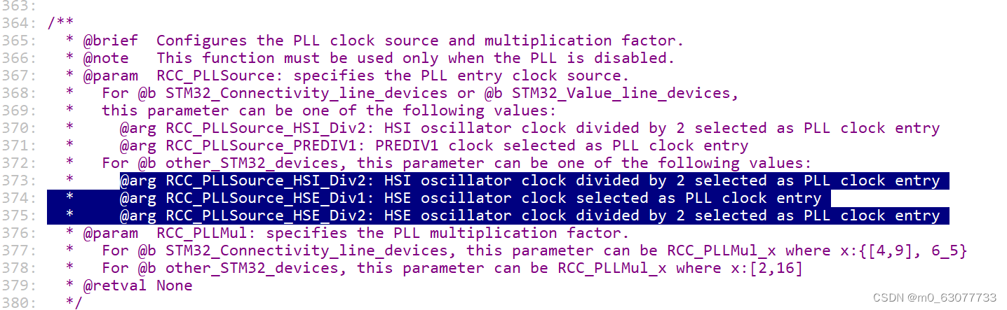
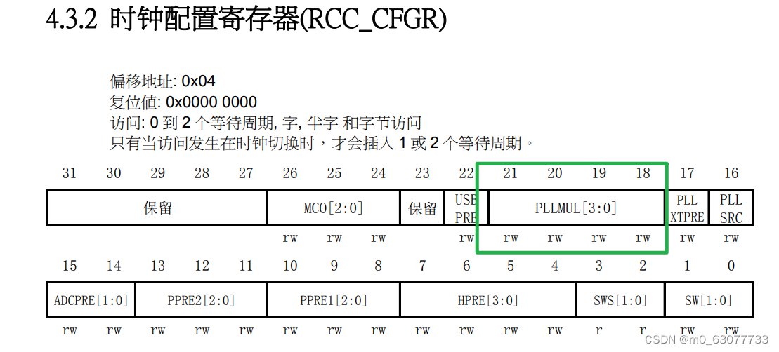
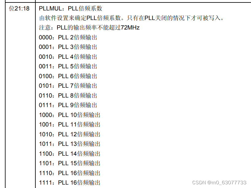
2.参数:时钟PLL倍频系数
3.代码理解
/**
* @brief Configures the PLL clock source and multiplication factor.
* @note This function must be used only when the PLL is disabled.
* @param RCC_PLLSource: specifies the PLL entry clock source.
* For @b STM32_Connectivity_line_devices or @b STM32_Value_line_devices,
* this parameter can be one of the following values:
* @arg RCC_PLLSource_HSI_Div2: HSI oscillator clock divided by 2 selected as PLL clock entry
* @arg RCC_PLLSource_PREDIV1: PREDIV1 clock selected as PLL clock entry
* For @b other_STM32_devices, this parameter can be one of the following values:
* @arg RCC_PLLSource_HSI_Div2: HSI oscillator clock divided by 2 selected as PLL clock entry
* @arg RCC_PLLSource_HSE_Div1: HSE oscillator clock selected as PLL clock entry
* @arg RCC_PLLSource_HSE_Div2: HSE oscillator clock divided by 2 selected as PLL clock entry
* @param RCC_PLLMul: specifies the PLL multiplication factor.
* For @b STM32_Connectivity_line_devices, this parameter can be RCC_PLLMul_x where x:{[4,9], 6_5}
* For @b other_STM32_devices, this parameter can be RCC_PLLMul_x where x:[2,16]
* @retval None
*/
void RCC_PLLConfig(uint32_t RCC_PLLSource, uint32_t RCC_PLLMul)
{
uint32_t tmpreg = 0;
/* Check the parameters */
assert_param(IS_RCC_PLL_SOURCE(RCC_PLLSource));
assert_param(IS_RCC_PLL_MUL(RCC_PLLMul));
tmpreg = RCC->CFGR;//我们要操纵的2个参数都在CFGR
/* Clear PLLSRC, PLLXTPRE and PLLMUL[3:0] bits */
tmpreg &= CFGR_PLL_Mask;//清零
/* Set the PLL configuration bits */
tmpreg |= RCC_PLLSource | RCC_PLLMul;//置1
/* Store the new value */
RCC->CFGR = tmpreg;
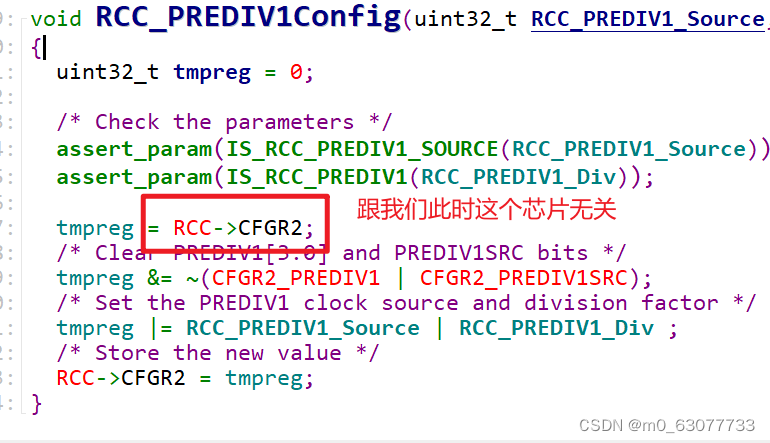
}7.RCC_PREDIV1Config(与F1无关,此处不看)
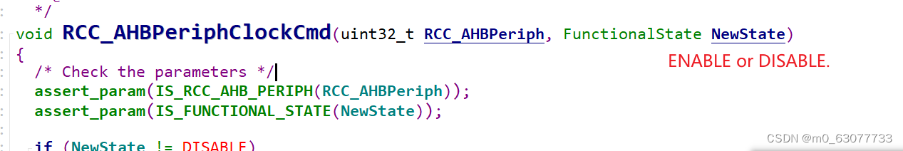
7.RCC_AHBPeriphClockCmd(外设时钟复位)
外设复位
/**
  * @brief  Enables or disables the AHB peripheral clock.
  * @param  RCC_AHBPeriph: specifies the AHB peripheral to gates its clock.
  *
  *   For @b STM32_Connectivity_line_devices, this parameter can be any combination
  *   of the following values:
  *     @arg RCC_AHBPeriph_DMA1
  *     @arg RCC_AHBPeriph_DMA2
  *     @arg RCC_AHBPeriph_SRAM
  *     @arg RCC_AHBPeriph_FLITF
  *     @arg RCC_AHBPeriph_CRC
  *     @arg RCC_AHBPeriph_OTG_FS
  *     @arg RCC_AHBPeriph_ETH_MAC
  *     @arg RCC_AHBPeriph_ETH_MAC_Tx
  *     @arg RCC_AHBPeriph_ETH_MAC_Rx
  *
  *   For @b other_STM32_devices, this parameter can be any combination of the
  *   following values:
  *     @arg RCC_AHBPeriph_DMA1
  *     @arg RCC_AHBPeriph_DMA2
  *     @arg RCC_AHBPeriph_SRAM
  *     @arg RCC_AHBPeriph_FLITF
  *     @arg RCC_AHBPeriph_CRC
  *     @arg RCC_AHBPeriph_FSMC
  *     @arg RCC_AHBPeriph_SDIO
  *
  * @note SRAM and FLITF clock can be disabled only during sleep mode.
  * @param  NewState: new state of the specified peripheral clock.
  *   This parameter can be: ENABLE or DISABLE.
  * @retval None
  */
void RCC_AHBPeriphClockCmd(uint32_t RCC_AHBPeriph, FunctionalState NewState)
{
  /* Check the parameters */
  assert_param(IS_RCC_AHB_PERIPH(RCC_AHBPeriph));
  assert_param(IS_FUNCTIONAL_STATE(NewState));

  if (NewState != DISABLE)
  {
    RCC->AHBENR |= RCC_AHBPeriph;
  }
  else
  {
    RCC->AHBENR &= ~RCC_AHBPeriph;
  }
}
8.RCC_HCLKConfig(AHB频率)
配置AHB clock
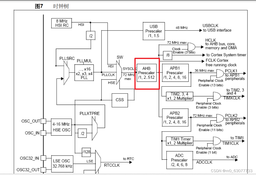
/**
* @brief Configures the AHB clock (HCLK).
* @param RCC_SYSCLK: defines the AHB clock divider. This clock is derived from
* the system clock (SYSCLK).
* This parameter can be one of the following values:
* @arg RCC_SYSCLK_Div1: AHB clock = SYSCLK
* @arg RCC_SYSCLK_Div2: AHB clock = SYSCLK/2
* @arg RCC_SYSCLK_Div4: AHB clock = SYSCLK/4
* @arg RCC_SYSCLK_Div8: AHB clock = SYSCLK/8
* @arg RCC_SYSCLK_Div16: AHB clock = SYSCLK/16
* @arg RCC_SYSCLK_Div64: AHB clock = SYSCLK/64
* @arg RCC_SYSCLK_Div128: AHB clock = SYSCLK/128
* @arg RCC_SYSCLK_Div256: AHB clock = SYSCLK/256
* @arg RCC_SYSCLK_Div512: AHB clock = SYSCLK/512
* @retval None
*/
void RCC_HCLKConfig(uint32_t RCC_SYSCLK)
{
uint32_t tmpreg = 0;
/* Check the parameters */
//判断要进行多少的分频
assert_param(IS_RCC_HCLK(RCC_SYSCLK));
//选择要进行操纵的寄存器
tmpreg = RCC->CFGR;
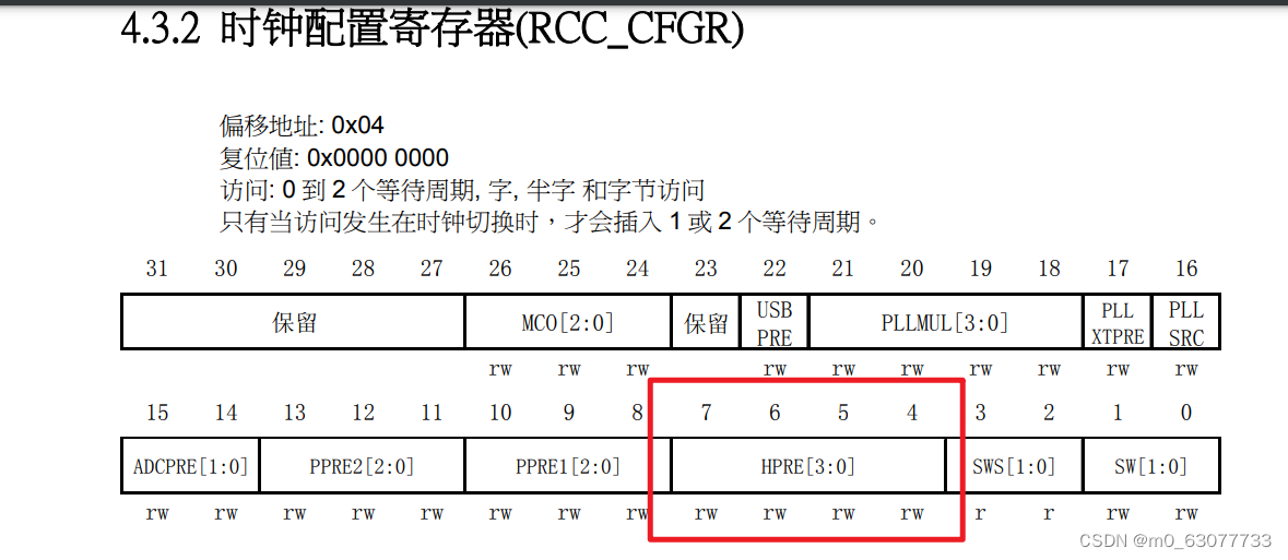
/* Clear HPRE[3:0] bits */
/**
CFGR_HPRE_Reset_Mask:0xFFFFFF0F==》0000 1111
*/
//表示将CFGR的bit4-bit7位置0
tmpreg &= CFGR_HPRE_Reset_Mask;
/* Set HPRE[3:0] bits according to RCC_SYSCLK value */
//表示将CFGR的bit4-bit7位置1
tmpreg |= RCC_SYSCLK;
/* Store the new value */
RCC->CFGR = tmpreg;
}9.RCC_PCLK1Config(APB1频率)/RCC_PCLK2Config(APB2频率)
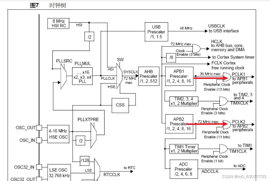
/**
* @brief Configures the Low Speed APB clock (PCLK1).
* @param RCC_HCLK: defines the APB1 clock divider. This clock is derived from
* the AHB clock (HCLK).
* This parameter can be one of the following values:
* @arg RCC_HCLK_Div1: APB1 clock = HCLK
* @arg RCC_HCLK_Div2: APB1 clock = HCLK/2
* @arg RCC_HCLK_Div4: APB1 clock = HCLK/4
* @arg RCC_HCLK_Div8: APB1 clock = HCLK/8
* @arg RCC_HCLK_Div16: APB1 clock = HCLK/16
* @retval None
*/
void RCC_PCLK1Config(uint32_t RCC_HCLK)
{
uint32_t tmpreg = 0;
/* Check the parameters */
assert_param(IS_RCC_PCLK(RCC_HCLK));
tmpreg = RCC->CFGR;
/* Clear PPRE1[2:0] bits */
tmpreg &= CFGR_PPRE1_Reset_Mask;
/* Set PPRE1[2:0] bits according to RCC_HCLK value */
tmpreg |= RCC_HCLK;
/* Store the new value */
RCC->CFGR = tmpreg;
}
/**
* @brief Configures the High Speed APB clock (PCLK2).
* @param RCC_HCLK: defines the APB2 clock divider. This clock is derived from
* the AHB clock (HCLK).
* This parameter can be one of the following values:
* @arg RCC_HCLK_Div1: APB2 clock = HCLK
* @arg RCC_HCLK_Div2: APB2 clock = HCLK/2
* @arg RCC_HCLK_Div4: APB2 clock = HCLK/4
* @arg RCC_HCLK_Div8: APB2 clock = HCLK/8
* @arg RCC_HCLK_Div16: APB2 clock = HCLK/16
* @retval None
*/
void RCC_PCLK2Config(uint32_t RCC_HCLK)
{
uint32_t tmpreg = 0;
/* Check the parameters */
assert_param(IS_RCC_PCLK(RCC_HCLK));
tmpreg = RCC->CFGR;
/* Clear PPRE2[2:0] bits */
tmpreg &= CFGR_PPRE2_Reset_Mask;
/* Set PPRE2[2:0] bits according to RCC_HCLK value */
tmpreg |= RCC_HCLK << 3;
/* Store the new value */
RCC->CFGR = tmpreg;
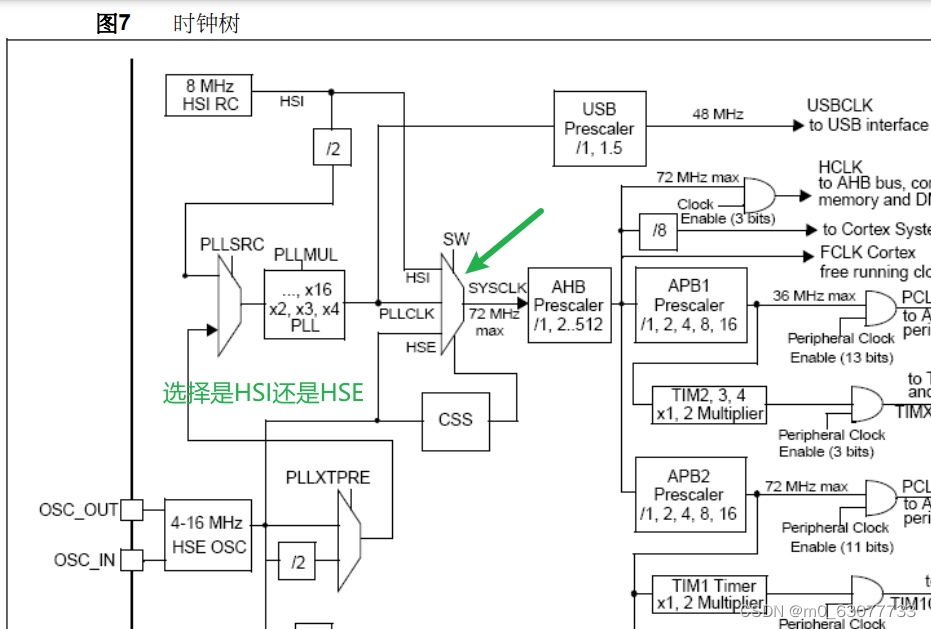
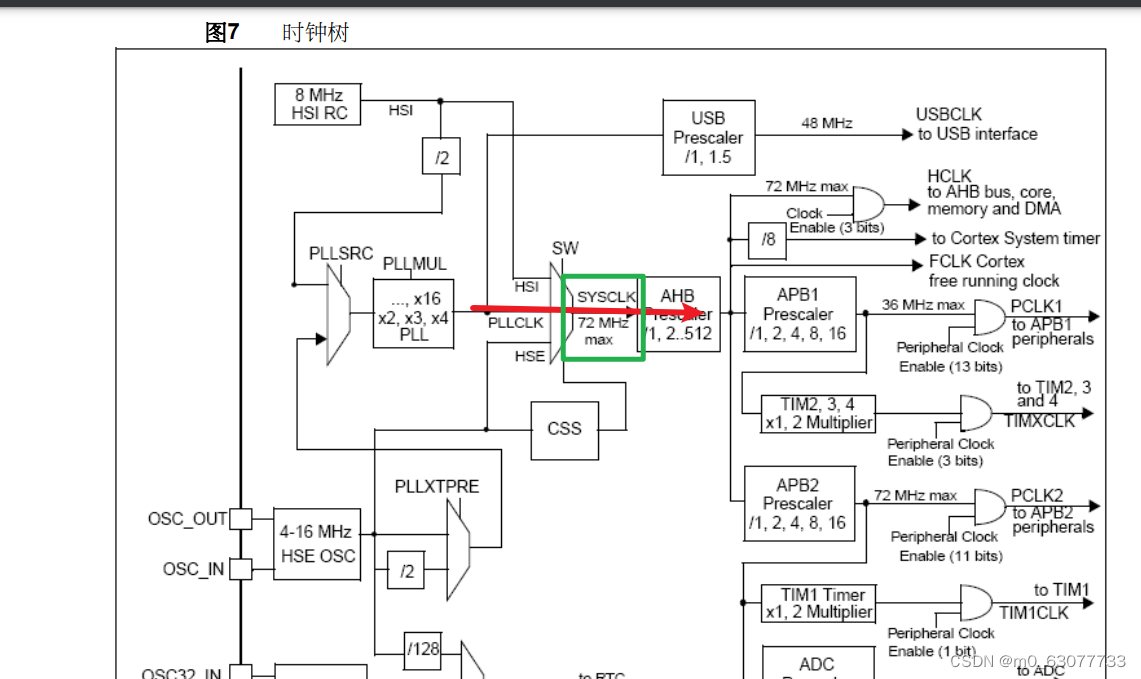
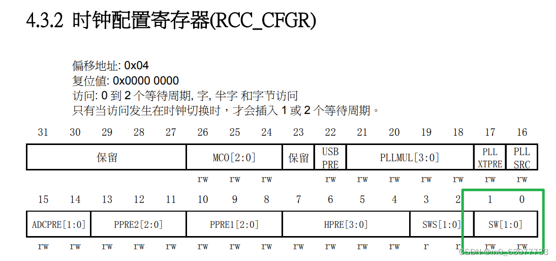
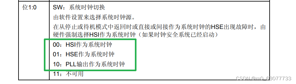
}10.RCC_SYSCLKConfig(选择使用哪一个作为系统时钟HSI/HSE/SYS)
/**
  * @brief  Configures the system clock (SYSCLK).
  * @param  RCC_SYSCLKSource: specifies the clock source used as system clock.
  *   This parameter can be one of the following values:
  *     @arg RCC_SYSCLKSource_HSI: HSI selected as system clock
  *     @arg RCC_SYSCLKSource_HSE: HSE selected as system clock
  *     @arg RCC_SYSCLKSource_PLLCLK: PLL selected as system clock
  * @retval None
  */
void RCC_SYSCLKConfig(uint32_t RCC_SYSCLKSource)
{
  uint32_t tmpreg = 0;
  /* Check the parameters */
  //判断用户输入的参数是否正确
  assert_param(IS_RCC_SYSCLK_SOURCE(RCC_SYSCLKSource));
  tmpreg = RCC->CFGR;
  /* Clear SW[1:0] bits */
  tmpreg &= CFGR_SW_Mask;//置0
  /* Set SW[1:0] bits according to RCC_SYSCLKSource value */
  tmpreg |= RCC_SYSCLKSource;//置1
  /* Store the new value */
  RCC->CFGR = tmpreg;
}
11.RCC_APB2PeriphResetCmd(外设的重新复位)
/**
  * @brief  Forces or releases High Speed APB (APB2) peripheral reset.
  * @param  RCC_APB2Periph: specifies the APB2 peripheral to reset.
  *   This parameter can be any combination of the following values:
  *     @arg RCC_APB2Periph_AFIO, RCC_APB2Periph_GPIOA, RCC_APB2Periph_GPIOB,
  *          RCC_APB2Periph_GPIOC, RCC_APB2Periph_GPIOD, RCC_APB2Periph_GPIOE,
  *          RCC_APB2Periph_GPIOF, RCC_APB2Periph_GPIOG, RCC_APB2Periph_ADC1,
  *          RCC_APB2Periph_ADC2, RCC_APB2Periph_TIM1, RCC_APB2Periph_SPI1,
  *          RCC_APB2Periph_TIM8, RCC_APB2Periph_USART1, RCC_APB2Periph_ADC3,
  *          RCC_APB2Periph_TIM15, RCC_APB2Periph_TIM16, RCC_APB2Periph_TIM17,
  *          RCC_APB2Periph_TIM9, RCC_APB2Periph_TIM10, RCC_APB2Periph_TIM11
  * @param  NewState: new state of the specified peripheral reset.
  *   This parameter can be: ENABLE or DISABLE.
  * @retval None
  */
void RCC_APB2PeriphResetCmd(uint32_t RCC_APB2Periph, FunctionalState NewState)
{
  /* Check the parameters */
  assert_param(IS_RCC_APB2_PERIPH(RCC_APB2Periph));
  assert_param(IS_FUNCTIONAL_STATE(NewState));
  if (NewState != DISABLE)
  {
    RCC->APB2RSTR |= RCC_APB2Periph;
  }
  else
  {
    RCC->APB2RSTR &= ~RCC_APB2Periph;
  }
}
4.注意点:
1.进制问题
我们在寄存器中的偏移量都是以十进制进行设置的,如果想要将其定义在宏定义中,记得将其转换为十六进制
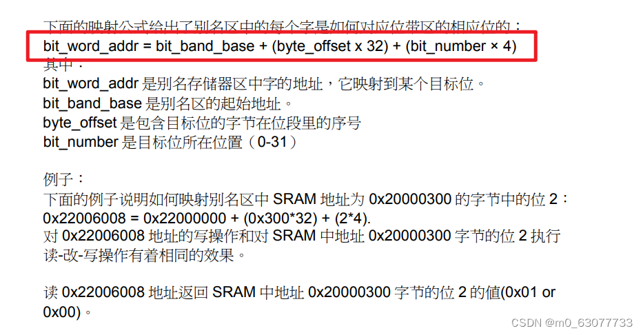
2.位段计算
5.使用库重写时钟设置函数
1.原始函数
#include "clock.h"
#include "gpio.h"
void Set_SysClockTo72M(void){
//检测外部晶振是否准备好
unsigned int Rcc_CR_HSE_Ready=0;
//等待开启PLL开启成功
unsigned int Rcc_CR_PLL_Ready=0;
//判断切换成PLL是否成功
unsigned int RCC_CF_SWS_PLL=0;
unsigned int faultTime=0;//判断等待是否超时
//一、复位RCC_CR寄存器
rRCC_CR = 0x00000083;
//二、开启外部时钟(外部晶振)
//第一步:先置0【将bit16清零】
rRCC_CR &= ~(1<<16);//关闭HSEON
//第二步:在置1
rRCC_CR |= (1<<16);//打开HSEON,让HSE开始工作
//三、检测外部时钟开启是否成功
do{
//检测HSEREAY(bit17)是否为1,1表示准备好
Rcc_CR_HSE_Ready=rRCC_CR&(1<<17);//取出bit17
faultTime++;
}while((faultTime<0x0fffffff) && (Rcc_CR_HSE_Ready==0));
//跳出do-while 1)要么超时2)要么准好了
//判断是超时还是准备好
//注意点:不能直接使用“Rcc_CR_HSE_Ready”因为rRCC_CR是需要读一次寄存器
//但是读出的结果可能还未改变,所以一定不能直接使用
if((rRCC_CR&(1<<17))!=0)//rRCC_CR&(1<<17)==1
{//这里HSE就ready,下面再去配置PLL并且等待他ready
//设置Flash
rFLASH_ACR |= 0x10;
rFLASH_ACR &= (~0x03);
rFLASH_ACR |= (0x02);
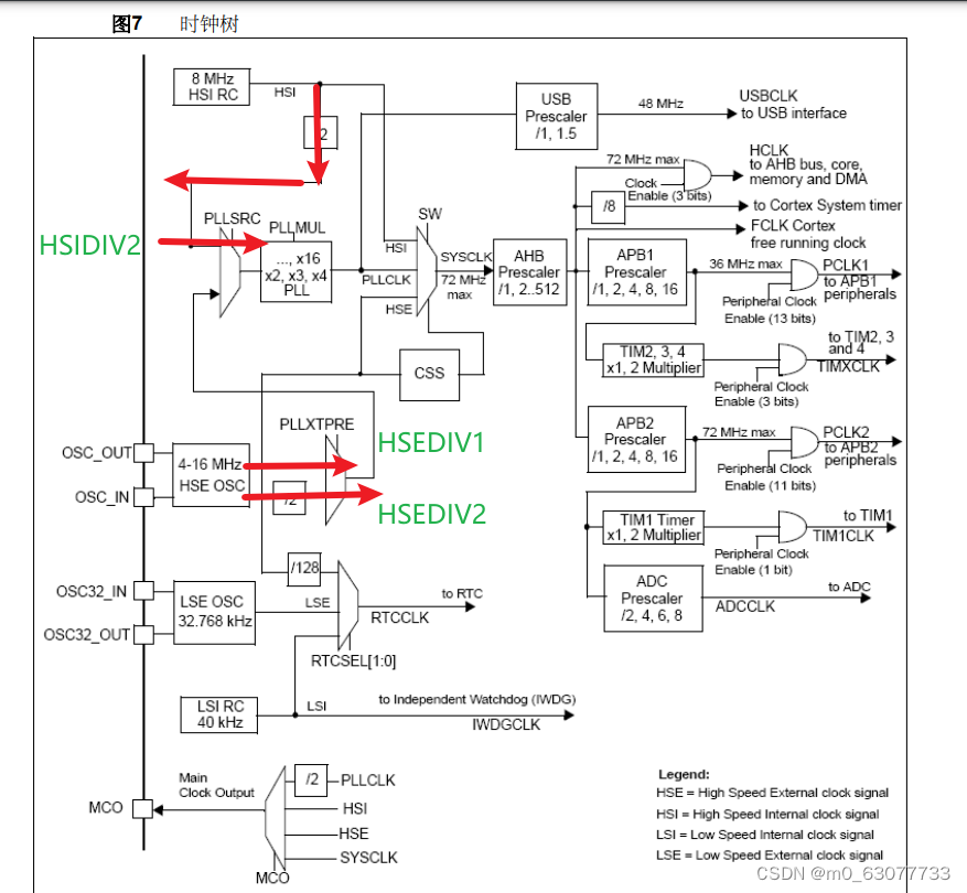
//四、对其进行预分频
//HPRE【AHB】:对应bit4-bit7:不分频(000)
//PPRE1【APB1】:对应bit8-bit10:进行二分频(100)
//PPRE2【APB2】:对应bit11-bit13:不分频(000)
//AHB和APB2未分频,APB1被2分频
//所以最终:AHB和APB2都是72MHZ,APB1是36MHZ
//第一步:先置0
rRCC_CFGR &=(~((0x0f<<4) | (0x07<<8) | (0x07<<11)));
//等价于:rRCC_CFGR=(~(0x3ff<<4));
//第二步:置1
rRCC_CFGR |=((0x0<<4) | (0x04<<8) | (0x0<<11));
//五、设置SHE为输入时钟,同时HSE不分频
//选择HSE作为PLL输入并且HSE不分频
//设置为输入时钟:bit16
//设置为不分频:bit17
//第一步:先置0
rRCC_CFGR &=(~((1<<16) | (1<<17)));
//第二步:置1,bit16
rRCC_CFGR |= ((1<<16) | (0<<17));
//六、设置PLL倍频系数
//9分频:0111:0x07
rRCC_CFGR &=(~(0x0f<<18));//清零bit18-bit21
rRCC_CFGR |= (0x07<<18);//设置为9倍频
//七、打开PLL开关
rRCC_CR |= (1<<24);
//八、等待开启PLL开启成功
//因为前面已经使用到,被累加了,使用这里要重新置0
faultTime=0;
do{
led_init();
Rcc_CR_PLL_Ready=rRCC_CR & (1<<25);//检测第25位是否为1
faultTime++;
}while((faultTime<0x0fffffff) && (Rcc_CR_PLL_Ready==0));
if((rRCC_CR & (1<<25)) == (1<<25)){
//到这里说明PLL已经稳定,可以用了,下面可以切换成外部时钟了
//九、切换成PLL
rRCC_CFGR &=(~(0x03)<<0);
rRCC_CFGR |=(0x02<<0);
//十、判断切换成PLL是否成功
//因为前面已经使用到,被累加了,使用这里要重新置0
faultTime=0;
do{
RCC_CF_SWS_PLL=rRCC_CFGR & (0x03<<2);//读出bit2-bit3
faultTime++;
led_init();
//0x02<<2:表示此时转换成PLL
}
while ((faultTime<0x0FFFFFFF) && (RCC_CF_SWS_PLL!=(0x02<<2)));
//十一、此时PLL转换成功
if((rRCC_CFGR & (0x03<<2))==(0x02<<2)){
//到这里我们的时钟整个就设置好了,可以结束了
}else{
//到这里说明PLL输出作为PLL失败
while(1);
}
}
else{
//到这里说明PLL启动时出错了,PLL不能稳定工作
while(1);
}
}else{//超时,或者未准备好,此时HSE不可以使用
while(1);
}
}
2.自己封装一个RCC_WaitForPLLStartUp
此处我们参考【RCC_WaitForHSEStartUp】这个函数来自己写
由源文件中没有定义【PLL_STARTUP_TIMEOUT】所以我们要自定义
#define PLL_STARTUP_TIMEOUT   ((uint16_t)0x0500000)


//本函数作用:等待PLL倍频后输出稳定
//返回值:SUCCESS说明未超时,ERROR超时
ErrorStatus RCC_WaitForPLLStartUp(void)
{

  __IO uint32_t StartUpCounter = 0;
  ErrorStatus status = ERROR;
  FlagStatus PLLStatus = RESET;

  /* Wait till HSE is ready and if Time out is reached exit */
  do
  {
  //读取寄存器的值
    PLLStatus = RCC_GetFlagStatus(RCC_FLAG_PLLRDY);
    StartUpCounter++;  //读取是否超时的
  } while((StartUpCounter != PLL_STARTUP_TIMEOUT) && (PLLStatus == RESET));

  //这里判断是防止超时
  if (RCC_GetFlagStatus(RCC_FLAG_PLLRDY) != RESET)
  {
    status = SUCCESS;
  }
  else
  {
  //超时
    status = ERROR;
  }
  return (status);
}
3.完整使用库函数的clock
//这个函数里面包含了全部外设头文件
#include "stm32f10x.h"
//等价于
//#include"stm32f10x_conf.h"
#define PLL_STARTUP_TIMEOUT ((uint16_t)0x0500000)
//本函数作用:等待PLL倍频后输出稳定
//返回值:SUCCESS说明未超时,ERROR超时
ErrorStatus RCC_WaitForPLLStartUp(void)
{
__IO uint32_t StartUpCounter = 0;
ErrorStatus status = ERROR;
FlagStatus PLLStatus = RESET;
/* Wait till HSE is ready and if Time out is reached exit */
do
{
//读取寄存器的值
PLLStatus = RCC_GetFlagStatus(RCC_FLAG_PLLRDY);
StartUpCounter++; //读取是否超时的
} while((StartUpCounter != PLL_STARTUP_TIMEOUT) && (PLLStatus == RESET));
//这里判断是防止超时
if (RCC_GetFlagStatus(RCC_FLAG_PLLRDY) != RESET)
{
status = SUCCESS;
}
else
{
//超时
status = ERROR;
}
return (status);
}
void Set_SysClockTo72M(void){
//接收判断回来的HSE是否已经稳定
ErrorStatus sta=ERROR;
//faultTime:用来判断是否超时
unsigned int faultTime=0;
unsigned int RCC_CF_SWS_PLL=0;
//一、先关闭HSEON然后在打开HSEON
RCC_HSEConfig(RCC_HSE_ON);
/*
rRCC_CR = 0x00000083;
rRCC_CR &= ~(1<<16);//关闭HSEON
rRCC_CR |= (1<<16);//打开HSEON,让HSE开始工作
*/
//二、等到HSE稳定
sta=RCC_WaitForHSEStartUp();
/*
do{
//检测HSEREAY(bit17)是否为1,1表示准备好
Rcc_CR_HSE_Ready=rRCC_CR&(1<<17);//取出bit17
faultTime++;
}while((faultTime<0x0fffffff) && (Rcc_CR_HSE_Ready==0));
//跳出do-while 1)要么超时2)要么准好了
*/
//三、判断是HSE稳定了还是超时了
if(sta==SUCCESS)
//if((rRCC_CR&(1<<17))!=0)//rRCC_CR&(1<<17)==1
{//这里HSE就ready,下面再去配置PLL并且等待他ready
//四、设置Flash
FLASH->ACR |= 0x10;
FLASH->ACR &= (~0x03);
FLASH->ACR |= (0x02);
/*
rFLASH_ACR |= 0x10;
rFLASH_ACR &= (~0x03);
rFLASH_ACR |= (0x02);
*/
//AHB和APB2未分频,APB1被2分频
//所以最终:AHB和APB2都是72MHZ,APB1是36MHZ
//五、配置相关的倍频信息
//配置HCLK为SYSCLK/1
RCC_HCLKConfig(RCC_SYSCLK_Div1);
//配置PCLK1为JCLK的2分频
RCC_PCLK1Config(RCC_HCLK_Div2);
//配置PCLK2为JCLK的1分频
RCC_PCLK2Config(RCC_HCLK_Div1);
/*
rRCC_CFGR &=(~((0x0f<<4) | (0x07<<8) | (0x07<<11)));
//等价于:rRCC_CFGR=(~(0x3ff<<4));
rRCC_CFGR |=((0x0<<4) | (0x04<<8) | (0x0<<11));
*/
//六、设置HSE/1为PLL时钟源,PLL倍频系数为9
RCC_PLLConfig(RCC_PLLSource_HSE_Div1,RCC_PLLMul_9);
/*
//设置SHE为输入时钟,同时HSE不分频
rRCC_CFGR &=(~((1<<16) | (1<<17)));
rRCC_CFGR |= ((1<<16) | (0<<17));
//设置PLL倍频系数
//9分频:0111:0x07
rRCC_CFGR &=(~(0x0f<<18));//清零bit18-bit21
rRCC_CFGR |= (0x07<<18);//设置为9倍频
*/
//七、打开PLL开关
RCC_PLLCmd(ENABLE);
//rRCC_CR |= (1<<24);
//因为HAL库中没有等到PLL的函数
//此处我们参考【RCC_WaitForHSEStartUp】这个函数来自己写
//八、等待开启PLL开启成功
sta=RCC_WaitForPLLStartUp();
/*
//因为前面已经使用到,被累加了,使用这里要重新置0
faultTime=0;
do{
led_init();
Rcc_CR_PLL_Ready=rRCC_CR & (1<<25);//检测第25位是否为1
faultTime++;
}while((faultTime<0x0fffffff) && (Rcc_CR_PLL_Ready==0));
*/
//九、判断PLL稳定还是超时
//if((rRCC_CR & (1<<25)) == (1<<25)){
if(sta==SUCCESS){
//到这里说明PLL已经稳定,可以用了,下面可以切换成外部时钟了
//九、切换成PLL
RCC_SYSCLKConfig(RCC_SYSCLKSource_PLLCLK);
/*
rRCC_CFGR &=(~(0x03)<<0);
rRCC_CFGR |=(0x02<<0);
*/
//十、判断切换成PLL是否成功
//因为前面已经使用到,被累加了,使用这里要重新置0
faultTime=0;
do{
RCC_CF_SWS_PLL=RCC->CFGR & (0x03<<2);//读出bit2-bit3
faultTime++;
//0x02<<2:表示此时转换成PLL
}
while ((faultTime<0x0FFFFFFF) && (RCC_CF_SWS_PLL!=(0x02<<2)));
//十一、此时PLL转换成功
if((RCC->CFGR & (0x03<<2))==(0x02<<2)){
//到这里我们的时钟整个就设置好了,可以结束了
}else{
//到这里说明PLL输出作为PLL失败
while(1);
}
}
else{
//到这里说明PLL启动时出错了,PLL不能稳定工作
while(1);
}
}else{//超时,或者未准备好,此时HSE不可以使用
while(1);
}
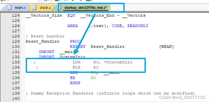
}6.SystmInit注意点:
我们在“startup_stm32f10x_md.s”文件中可以看到在执行main函数之前会先执行一个“SystemInit”函数
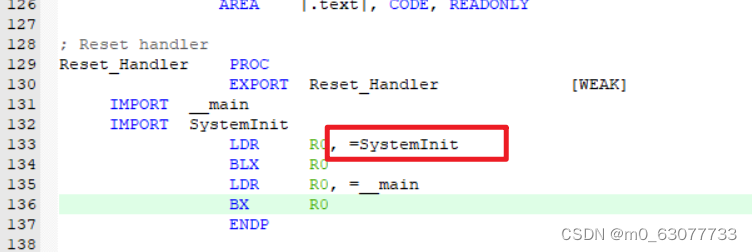
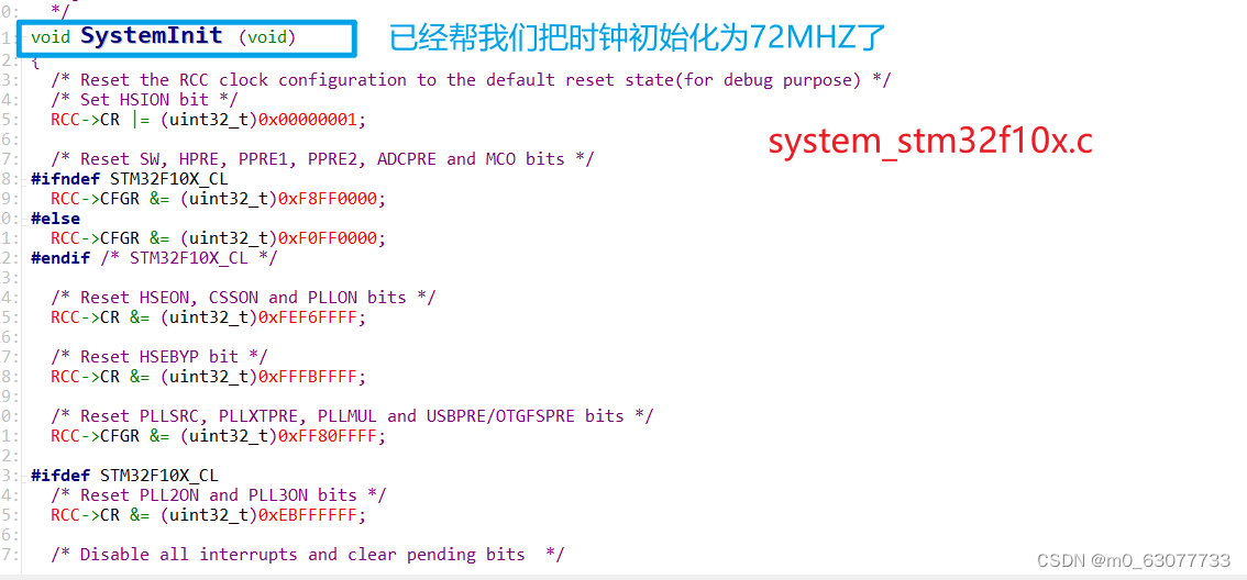
所以如果我们想要使用自己的设置72MHZ频率的函数,则应该将SystemInit注释调。


![[Ubuntu 18.04] 搭建文件夹共享之Samba服务器](https://img-blog.csdnimg.cn/f0fd09f6eead4bf5b2116fb3578069fb.png?x-oss-process=image/watermark,type_d3F5LXplbmhlaQ,shadow_50,text_Q1NETiBATmV1dGlvbndlaQ==,size_20,color_FFFFFF,t_70,g_se,x_16)