三层架构实验
- 拓扑和思路
- 拓扑
- 思路
- LSW配置
- LSW1
- LSW2
- LSW3
- DHCP
- LSW2
- LSW1
- ACL外网
- 冗余
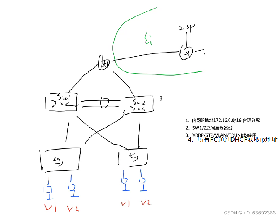
拓扑和思路
拓扑
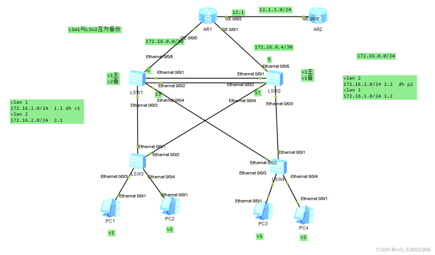
思路
首先划分网段,然后LSW1和LSW2和R1可以用ospf宣告就行,然后R1写条缺省指向R2
然后可以将LSW1和LSW2三合一,给交换机配置换分组,将对应VLAN划分到对应的组,将LSW1作为VLAN1的主设备,作为VLAN1的备用设备。将LSW2作为VLAN2的主设备,作为VLAN1的备用设备。
然后将pc1和pc2分别划分到VLAN1和VLAN2,其他接口可以设置Trunk干道
dhcp可以在LSW1和LSW2上创建地址池,配置跟路由器一样
假设LSW1和LSW2有断连的风险,可以将pc的网关设置成虚拟网关,因为路由器本质其实是通过ip获取的mac地址,这样我们只需要知道mac地址就行了,LSW1和LSW1之间有hello,如果LSW1断了LSW2就然pc获取自己的mac,但是这个只限于接口不变,这样就起到了备份的作用,记住冗余的时候要改优先级,主设备大优
最后外网写条acl就行了
LSW配置
LSW1
LSW1
[LSW1]interface Eth-Trunk 0              将E 0/0/1和E 0/0/2两条链路聚合, 增加带宽 ,提高可靠性
[LSW1]int e0/0/1
[LSW1-Ethernet0/0/1]eth-trunk 0
[LSW1-Ethernet0/0/1]int e0/0/2
[LSW1-Ethernet0/0/2]eth-trunk 0
[LSW1-Ethernet0/0/2]q


[LSW1]port-group group-member Ethernet 0/0/3 Ethernet 0/0/4    设置trunk干道就行了
[LSW1-port-group]port link-type trunk
[LSW1-Ethernet0/0/3]port link-type trunk
[LSW1-Ethernet0/0/4]port link-type trunk
[LSW1-port-group]port trunk allow-pass vlan 2
[LSW1-Ethernet0/0/3]port trunk allow-pass vlan 2
[LSW1-Ethernet0/0/4]port trunk allow-pass vlan 2


[LSW1]int Eth-Trunk 0
[LSW1-Eth-Trunk0]port link-type trunk
[LSW1-Eth-Trunk0]port trunk allow-pass vlan 2


生成树


[LSW1]stp region-configuration
[LSW1-mst-region]region-name 1   取名
[LSW1-mst-region]instance 1 vlan 1  将vlan1划入组1
[LSW1-mst-region]instance 2 vlan 2
[LSW1-mst-region]active region-configuration  激活配置


子接口SVI
[LSW1]interface Vlanif 1   这里创建虚拟
[LSW1-Vlanif1]ip address 172.16.1.1 24  设置ip
[LSW1]interface Vlanif 2
[LSW1-Vlanif2]ip address 172.16.2.1 24


[LSW1]stp in
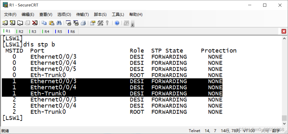
[LSW1]stp instance 1 root primary  当组1的主根
[LSW1]stp instance 2 root secondary    当组2的备份根
LSW2
LSW2
[LSW2]interface Eth-Trunk 0            将E 0/0/1和E 0/0/2两条链路聚合, 增加带宽 ,提高可靠性
[LSW2-Eth-Trunk0]int e0/0/1
[LSW2-Ethernet0/0/1]eth-trunk 0
[LSW2-Ethernet0/0/1]int e0/0/2
[LSW2-Ethernet0/0/2]eth-trunk 0
[LSW2-Ethernet0/0/2]q


[LSW2]port-group group-member Ethernet 0/0/4 Ethernet 0/0/3     设置trunk干道
[LSW2-port-group]port link-type trunk
[LSW2-Ethernet0/0/4]port link-type trunk
[LSW2-Ethernet0/0/3]port link-type trunk
[LSW2-port-group]port trunk allow-pass vlan 2
[LSW2-Ethernet0/0/4]port trunk allow-pass vlan 2
[LSW2-Ethernet0/0/3]port trunk allow-pass vlan 2


[LSW2]int Eth-Trunk 0
[LSW2-Eth-Trunk0]port link-type trunk
[LSW2-Eth-Trunk0]port trunk allow-pass vlan 2


[LSW2]int Vlanif 1
[LSW2-Vlanif1]ip ad
[LSW2-Vlanif1]ip address 172.16.1.2 24
[LSW2-Vlanif1]q
[LSW2]int Vlanif 2
[LSW2-Vlanif2]ip ad
[LSW2-Vlanif2]ip address 172.16.2.2 24


生成树
[LSW2]stp region-configuration
[LSW2-mst-region] region-name 1
[LSW2-mst-region] instance 1 vlan 1   将vlan2划分到组1
[LSW2-mst-region] instance 2 vlan 2     将vlan2划分到组2
[LSW2-mst-region] active region-configuration   激活配置


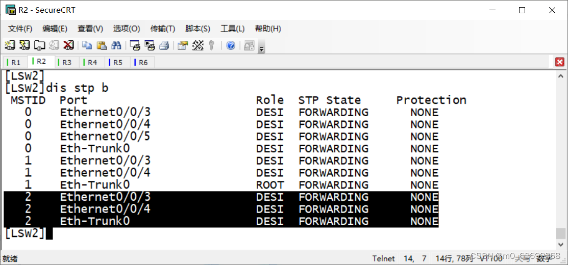
[LSW2]stp instance 1 root secondary   这里选举主从, 显示1是从,2是主
[LSW2]stp instance 2
[LSW2]stp instance 2 root primary
[LSW2]
LSW3
LSW3
[LSW3]port-group group-member Ethernet 0/0/1 Ethernet 0/0/2   设置trunk干道
[LSW3-port-group]port link-type trunk
[LSW3-Ethernet0/0/1]port link-type trunk
[LSW3-Ethernet0/0/2]port link-type trunk
[LSW3-port-group]port trunk allow-pass vlan 2
[LSW3-Ethernet0/0/1]port trunk allow-pass vlan 2
[LSW3-Ethernet0/0/2]port trunk allow-pass vlan 2
[LSW3-port-group]


[LSW3]int e0/0/3
[LSW3-Ethernet0/0/3]port link-type access
[LSW3-Ethernet0/0/3]port default vlan 1
[LSW3-Ethernet0/0/3]int e0/0/4
[LSW3-Ethernet0/0/4]port link-type access
[LSW3-Ethernet0/0/4]port default vlan 2
[LSW3-Ethernet0/0/4]

生成树
[LSW3]stp region-configuration
[LSW3-mst-region] region-name 1
[LSW3-mst-region] instance 1 vlan 1
[LSW3-mst-region] instance 2 vlan 2
[LSW3-mst-region] active region-configuration
### LSW4 LSW4
[LSW4]port-group group-member Ethernet 0/0/1 Ethernet 0/0/2
[LSW4-port-group]port link-type trunk
[LSW4-Ethernet0/0/1]port link-type trunk
[LSW4-Ethernet0/0/2]port link-type trunk
[LSW4-port-group]port trunk allow-pass vlan 2
[LSW4-Ethernet0/0/1]port trunk allow-pass vlan 2
[LSW4-Ethernet0/0/2]port trunk allow-pass vlan 2


[LSW4]int e0/0/3
[LSW4-Ethernet0/0/3]port link-type access
[LSW4-Ethernet0/0/3]port default vlan 1
[LSW4-Ethernet0/0/3]int e0/0/4
[LSW4-Ethernet0/0/4]port link-type access
[LSW4-Ethernet0/0/4]port default vlan 2


生成树

[LSW4]stp region-configuration
[LSW4-mst-region] region-name 1
[LSW4-mst-region] instance 1 vlan 1    将vlan1划分到组1
[LSW4-mst-region] instance 2 vlan 2    将vlan2划分到组2
[LSW4-mst-region] active region-configuration
DHCP
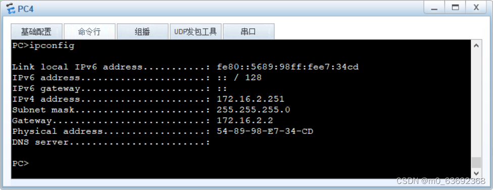
LSW2
interface Vlanif2
 ip address 172.16.2.2 255.255.255.0
 dhcp select global
#
创建的池塘


LSW1
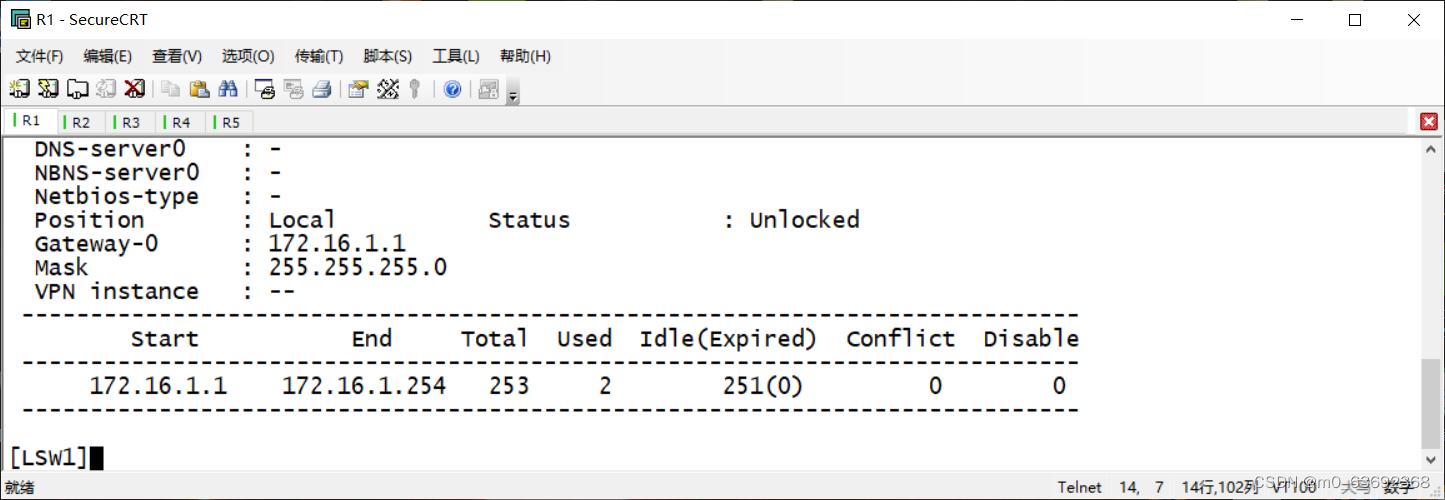
#
interface Vlanif1
 ip address 172.16.1.1 255.255.255.0
 dhcp select global
#
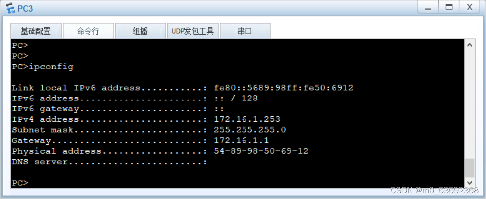
创建的池塘

ACL外网
在R1和LSW1和LSW2上开启ospf协议然后宣告就行了,可以直接宣告172.16.0.0网段
R2
[R1]ip route-static 0.0.0.0 0 12.1.1.2  先写一条到外网的缺省
[R1]acl n
[R1]acl 2000
[R1-acl-basic-2000]rule permit source 172.16.0.0 0.0.255.255
[R1-acl-basic-2000]rule permit source 1.1.1.1 0.0.0.0
[R1]int g0/0/2
[R1-GigabitEthernet0/0/2]nat outbound 2000
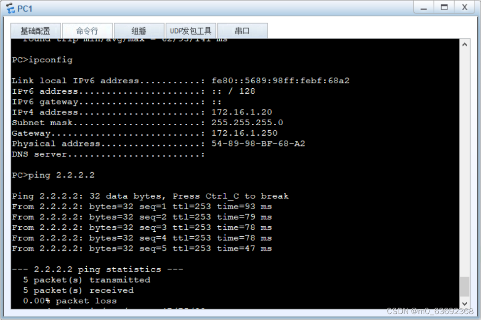
测试

冗余
[LSW1]int v
[LSW1]int Vlanif 1
[LSW1-Vlanif1]vrrp vrid 1 virtual-ip 172.16.1.250  虚拟网关
[LSW1-Vlanif1]vrrp vrid 1 priority 110   改优先级,大优
[LSW2]int Vlanif 1
[LSW2-Vlanif1]vrrp vrid 1 virtual-ip 172.16.1.250  可以不改优先级,比主低就行
这里显示R1是主

改下网关试试

测试
