1、rtl8221b是一款2.5g的光电转换的phy
系统的构建如下
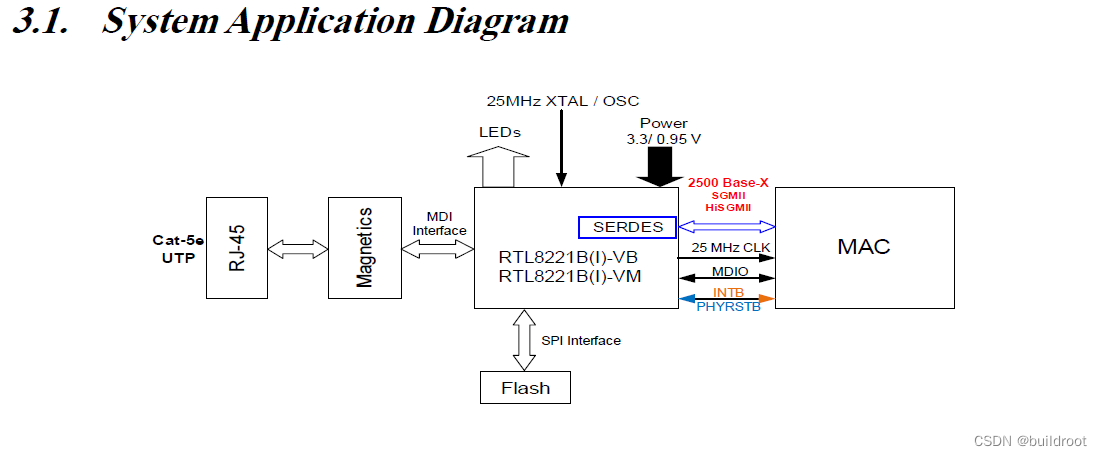
为了省成本,不用mac来对接其中的gmii接口直接接光模块
2、mdio和mdc由mcu的gpio来模拟,在csdn上有很多的文章来参考
mdio的参数如下

不想看英文可以参考下面的文章
MDIO(clause 22 与 clause 45)接口简介以及FPGA Verilog 实现_Angry Noob的博客-CSDN博客
MDIO分成Clause 22和Clause 45还有Clause 35等,但是因为这款芯片只提到了22和45并且用22的话需要间接访问13和14寄存器才能正常工作,没有必要弄得这么的复杂,只使用C45即可,gpio的模拟参考linux内核的源码中的mdio-bitbang.c中的代码,如下
// SPDX-License-Identifier: GPL-2.0
/*
 * Bitbanged MDIO support.
 *
 * Author: Scott Wood <scottwood@freescale.com>
 * Copyright (c) 2007 Freescale Semiconductor
 *
 * Based on CPM2 MDIO code which is:
 *
 * Copyright (c) 2003 Intracom S.A.
 *  by Pantelis Antoniou <panto@intracom.gr>
 *
 * 2005 (c) MontaVista Software, Inc.
 * Vitaly Bordug <vbordug@ru.mvista.com>
 */

#include <linux/module.h>
#include <linux/mdio-bitbang.h>
#include <linux/types.h>
#include <linux/delay.h>

#define MDIO_READ 2
#define MDIO_WRITE 1

#define MDIO_C45 (1<<15)
#define MDIO_C45_ADDR (MDIO_C45 | 0)
#define MDIO_C45_READ (MDIO_C45 | 3)
#define MDIO_C45_WRITE (MDIO_C45 | 1)

#define MDIO_SETUP_TIME 10
#define MDIO_HOLD_TIME 10

/* Minimum MDC period is 400 ns, plus some margin for error.  MDIO_DELAY is done twice per period.
 */
#define MDIO_DELAY 250

/* The PHY may take up to 300 ns to produce data, plus some margin
 * for error.
 */
#define MDIO_READ_DELAY 350

/* MDIO must already be configured as output. */
static void mdiobb_send_bit(struct mdiobb_ctrl *ctrl, int val)
{
	const struct mdiobb_ops *ops = ctrl->ops;

	ops->set_mdio_data(ctrl, val);
	ndelay(MDIO_DELAY);
	ops->set_mdc(ctrl, 1);
	ndelay(MDIO_DELAY);
	ops->set_mdc(ctrl, 0);
}

/* MDIO must already be configured as input. */
static int mdiobb_get_bit(struct mdiobb_ctrl *ctrl)
{
	const struct mdiobb_ops *ops = ctrl->ops;

	ndelay(MDIO_DELAY);
	ops->set_mdc(ctrl, 1);
	ndelay(MDIO_READ_DELAY);
	ops->set_mdc(ctrl, 0);

	return ops->get_mdio_data(ctrl);
}

/* MDIO must already be configured as output. */
static void mdiobb_send_num(struct mdiobb_ctrl *ctrl, u16 val, int bits)
{
	int i;

	for (i = bits - 1; i >= 0; i--)
		mdiobb_send_bit(ctrl, (val >> i) & 1);
}

/* MDIO must already be configured as input. */
static u16 mdiobb_get_num(struct mdiobb_ctrl *ctrl, int bits)
{
	int i;
	u16 ret = 0;

	for (i = bits - 1; i >= 0; i--) {
		ret <<= 1;
		ret |= mdiobb_get_bit(ctrl);
	}

	return ret;
}

/* Utility to send the preamble, address, and
 * register (common to read and write).
 */
static void mdiobb_cmd(struct mdiobb_ctrl *ctrl, int op, u8 phy, u8 reg)
{
	const struct mdiobb_ops *ops = ctrl->ops;
	int i;

	ops->set_mdio_dir(ctrl, 1);

	/*
	 * Send a 32 bit preamble ('1's) with an extra '1' bit for good
	 * measure.  The IEEE spec says this is a PHY optional
	 * requirement.  The AMD 79C874 requires one after power up and
	 * one after a MII communications error.  This means that we are
	 * doing more preambles than we need, but it is safer and will be
	 * much more robust.
	 */

	for (i = 0; i < 32; i++)
		mdiobb_send_bit(ctrl, 1);

	/* send the start bit (01) and the read opcode (10) or write (01).
	   Clause 45 operation uses 00 for the start and 11, 10 for
	   read/write */
	mdiobb_send_bit(ctrl, 0);
	if (op & MDIO_C45)
		mdiobb_send_bit(ctrl, 0);
	else
		mdiobb_send_bit(ctrl, 1);
	mdiobb_send_bit(ctrl, (op >> 1) & 1);
	mdiobb_send_bit(ctrl, (op >> 0) & 1);

	mdiobb_send_num(ctrl, phy, 5);
	mdiobb_send_num(ctrl, reg, 5);
}

/* In clause 45 mode all commands are prefixed by MDIO_ADDR to specify the
   lower 16 bits of the 21 bit address. This transfer is done identically to a
   MDIO_WRITE except for a different code. To enable clause 45 mode or
   MII_ADDR_C45 into the address. Theoretically clause 45 and normal devices
   can exist on the same bus. Normal devices should ignore the MDIO_ADDR
   phase. */
static int mdiobb_cmd_addr(struct mdiobb_ctrl *ctrl, int phy, u32 addr)
{
	unsigned int dev_addr = (addr >> 16) & 0x1F;
	unsigned int reg = addr & 0xFFFF;
	mdiobb_cmd(ctrl, MDIO_C45_ADDR, phy, dev_addr);

	/* send the turnaround (10) */
	mdiobb_send_bit(ctrl, 1);
	mdiobb_send_bit(ctrl, 0);

	mdiobb_send_num(ctrl, reg, 16);

	ctrl->ops->set_mdio_dir(ctrl, 0);
	mdiobb_get_bit(ctrl);

	return dev_addr;
}

static int mdiobb_read(struct mii_bus *bus, int phy, int reg)
{
	struct mdiobb_ctrl *ctrl = bus->priv;
	int ret, i;

	if (reg & MII_ADDR_C45) {
		reg = mdiobb_cmd_addr(ctrl, phy, reg);
		mdiobb_cmd(ctrl, MDIO_C45_READ, phy, reg);
	} else
		mdiobb_cmd(ctrl, MDIO_READ, phy, reg);

	ctrl->ops->set_mdio_dir(ctrl, 0);

	/* check the turnaround bit: the PHY should be driving it to zero, if this
	 * PHY is listed in phy_ignore_ta_mask as having broken TA, skip that
	 */
	if (mdiobb_get_bit(ctrl) != 0 &&
	    !(bus->phy_ignore_ta_mask & (1 << phy))) {
		/* PHY didn't drive TA low -- flush any bits it
		 * may be trying to send.
		 */
		for (i = 0; i < 32; i++)
			mdiobb_get_bit(ctrl);

		return 0xffff;
	}

	ret = mdiobb_get_num(ctrl, 16);
	mdiobb_get_bit(ctrl);
	return ret;
}

static int mdiobb_write(struct mii_bus *bus, int phy, int reg, u16 val)
{
	struct mdiobb_ctrl *ctrl = bus->priv;

	if (reg & MII_ADDR_C45) {
		reg = mdiobb_cmd_addr(ctrl, phy, reg);
		mdiobb_cmd(ctrl, MDIO_C45_WRITE, phy, reg);
	} else
		mdiobb_cmd(ctrl, MDIO_WRITE, phy, reg);

	/* send the turnaround (10) */
	mdiobb_send_bit(ctrl, 1);
	mdiobb_send_bit(ctrl, 0);

	mdiobb_send_num(ctrl, val, 16);

	ctrl->ops->set_mdio_dir(ctrl, 0);
	mdiobb_get_bit(ctrl);
	return 0;
}

struct mii_bus *alloc_mdio_bitbang(struct mdiobb_ctrl *ctrl)
{
	struct mii_bus *bus;

	bus = mdiobus_alloc();
	if (!bus)
		return NULL;

	__module_get(ctrl->ops->owner);

	bus->read = mdiobb_read;
	bus->write = mdiobb_write;
	bus->priv = ctrl;

	return bus;
}
EXPORT_SYMBOL(alloc_mdio_bitbang);

void free_mdio_bitbang(struct mii_bus *bus)
{
	struct mdiobb_ctrl *ctrl = bus->priv;

	module_put(ctrl->ops->owner);
	mdiobus_free(bus);
}
EXPORT_SYMBOL(free_mdio_bitbang);

MODULE_LICENSE("GPL v2");
3、配置寄存器

配置任意寄存器,其中的RW是可读可写的,RO是只读的寄存器
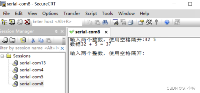
如图配置其中的12位的自适应寄存器,只需要将值置位即可,默认值为0x3000,将其关闭之后就成了0x2000,读取数据后通过串口发出如下图所示
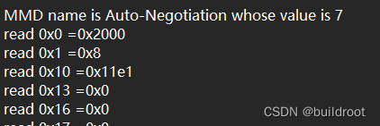
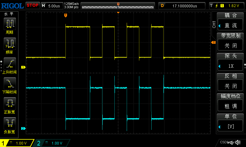
与设置的值一致,所以成功了,如果是mdio读取的值为0xffff用示波器测试后一直是高电平,那么就需要检查了。
下面例出开发中的问题
1、mdio的数据是全1的数据即0xffff
检查mdio和mdc的接口,我在测试的时候因为没有预留这两个接口的引脚导致我用线引出后手没有拉好直接将mdio口拉掉了,导致在示波器上可以看到波形,但是这个波是没有到phy的
检查phy的(端口)地址,设备地址(寄存器的前导),以及寄存器的地址(address/data),是否正确,可以通过观察led来确定phy是否是正确的地址。
2、led不亮,或者只亮一盏两盏
引起这个问题的因素比较多,因为当时采用的芯片的主频是64m按理来说使用最高的频64m就行了,但是后续的使用发现这个频率很不稳定,在烧写过程中时好时坏,建议使用25的倍数的频率,这里使用50m就行,只要满足mdc所需的0-2.5m即可,我尝试用过250hz和1.5khz,效果都不错。
3、MDI接口的信号有误
MDI即第一张图中的电口,我遇到过几个问题,现在总结,首先是mdi的信道不对,检查引脚mdi_swap的置位与自己设计的是否一致,开始我置位了,但是因为有其他问题我改了这个脚的状态导致硬件工程师用的双绞线没有一起改变,配置成100m的时候信道反了,于是信号灯就不闪了,另外在设计的时候因为丝印错了没有和焊工说明清楚导致电阻过大,信号被严重削弱导致电口信号不通

