用于FPGA远程更新的QuickBoot方法
用于FPGA远程更新的QuickBoot方法
- 用于FPGA远程更新的QuickBoot方法
- 1. 远程更新简介
- 2 QuickBoot方案
- 2.1 QuickBoot配置方法
- 2.2 QuickBoot Flash 编程方法
- 3.QuickBoot实现
- 3.1 Critical Switch World (key point)
- 3.2 QuickBoot存储映射
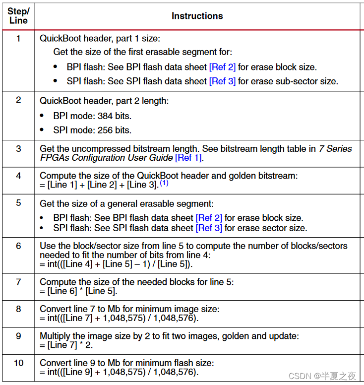
- 3.3 Bitstream Image 大小与Flash存储大小选择
- 4. QuickBoot参考设计实现指南
- 参考
1. 远程更新简介
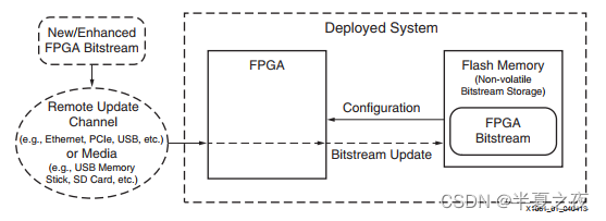
下图为具有FPGA远程更新功能的系统架构:
在FPGA设计中,FPGA固件主要烧录到flash中。
2 QuickBoot方案
QuickBoot远程更新方案是一种用于FPGA固件远程更新的解决方案;
该方案对固件更新过程的编程算法进行简单调整,将编程错误/中断复的责任置于编程操作上
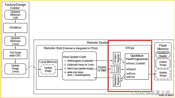
下图展示了QuickBoot的系统架构框图:
- Factory / Design Center:
- Vivado 生成Bitstream
- 将Bitstream 转换成 Memory Configuration File (.mcs)
- 使用QuickBoot方案提供的Perl脚本添加CRC数据,并产生新的 Memory Configuration File
- Remote System:
- Remote Host, 远程更新接口(如以太网、PCIe、USB等)
- QuickBoot Flash Progammer, VHDL code(QuickBoot提供)
- Flash Memory: (QuickBoot 方案中 Flash模型)
- QuickBoot Header Area
- Golden Image Area
- Update Image Area
2.1 QuickBoot配置方法
在QuickBoot解决方案中,将Flash Memory划分为以下三个部分:
- Special QuickBoot Head (特殊的QuickBoot头)
Critical Switch Word(详细介绍见章节3.1): QuickBoot配置方法的关键,Critical Switch World为ON时,FPGA加载Update Bitstream;Critical Switch World为OFF时,FPGA加载Golden Bitstream- Warm Boot Jump Sequence
- Golden Bitstream Image Area
- Update Bitstream Image Area
QuickBoot 配置序列过程如下:
- 从Flash 地址0处开始读数据; 从
Critical Switch World地址处读出Critical Switch World的值,若为ON,则执行Warm Boot Jump Sequence跳到步骤2加载Update Bitstream;反之Critical Switch World为OFF,则忽略Warm Boot Jump Sequence, 跳到步骤3加载Golden Bitstream - Configure with the update bitstream:
- Jump to update bitstream area
- Load the bitstream from the update bitstream area.
- Configure with the golden bitstream:
- 继续按照Flash存储器地址顺序读取 Golden bitstream area数据
- Load the bitstream from the golden bitstream area
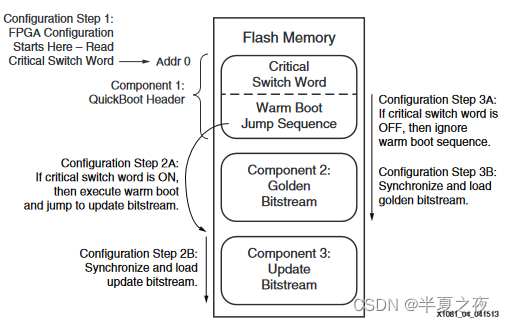
总结: QuickBoot配置方法可以通过Critical Switch World快速确定加载哪个bitstream; 然后读取选中区域的bitstream来配置FPGA
2.2 QuickBoot Flash 编程方法
Update bitstream编程过程决定了QuickBoot方案的健壮性
为了确保QuickBoot方案可靠,Flash编程要确保
- 在尝试对Update bitstream进行任何更改之前,
Critical Switch World一定是OFF; - 只有在验证Update bitstream已经被正确编程之后,
Critical Switch World才设置为ON - 为了在所有情况下的完整性,不能修改QuickBoot Header 中Warm Boot Jump Sequence 以及 Golden Image
总结: QuickBoot 提供的 QuickBoot Flash Progammer行为说明(VHDL设计功能)
3.QuickBoot实现
3.1 Critical Switch World (key point)
关键开关字是一个特殊的字值。 只有当关键开关字位置包含一个精确的、预定的值时,关键开关字才被认为是ON。
关键开关字的操作和其特殊的值 与FPGA bistream以及FPGA内建配置逻辑存在一定的关系
Xilinx FPGA配置通过一系列32-bit字完成,这些32-bit字包含:
- Bus width auto detection word
- Sync word
- Packet header word
- Packet command or data words for each packet.
由Xilinx 设计工具产生的所有bitstream按照顺序由以下部分组成:
- Bus width auto detection word
- Sync word
- data packets that define the FPGA configuration
BPI Flash:
- FPGA 配置逻辑保持在初始阶段,直到FPGA在BPI Flash D[0:7] 引脚上检测到0xBB 数据值(从总线宽度自动检测模式的第一个字开始)
- 在FPGA初始
搜索总线宽度自动检测模式期间,FPGA 会有效地忽略所有传入数据`,直到识别出有效的总线宽度自动检测模式 - 因此,BPI类型的Flash,总线宽度自动检测模式 0x000000BB 的第一个字是 QuickBoot 方法的关键开关字
(注:关键开关字位置不是总线宽度自动检测字时,FPGA内建配置程序就忽略warm boot jump sequence)
SPI Flash:
- FPGA 配置逻辑保持在初始阶段,监视传入数据中的同步字 0xAA995566 ,以实现自身与传入比特流的 32 位字的边界同步
在初始搜索同步字期间,FPGA 会有效地忽略所有传入数据,直到识别出同步字- 因此,SPI类型Flash, 将同步字作为QuickBoot方案的关键开关字
(注:关键开关字位置不是同步字时,FPGA内建配置程序就忽略warm boot jump sequence)

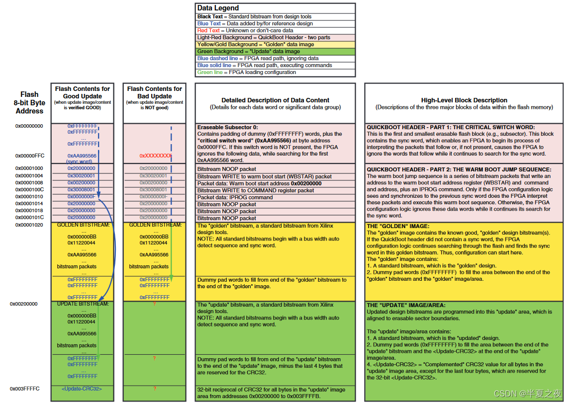
3.2 QuickBoot存储映射
由于Flash的修改需要擦除操作,并且擦除操作会影响整个Flash segment,因此Flash segment结构决定了 QuickBoot 各部分在Flash内的位置:
- QuickBoot Header
a. QuickBoot Header part 1——Critical Switch World, 放置在单独的可擦除segment
b. QuickBoot Header part 2——Warm Boot Jump Sequence, 紧随part1,但处于与part 1部分不同的可擦除segment - Golden bitstream image在Flash存储阵列中紧随QuickBoot Header之后 , Xilinx设计工具产生的标准bitstream(即包含bus width auto detetced word and sync word)
- Update bitstream image存放在自己独立的可擦除segment; Update Bitstream image 和Golden bitstream image不共享任何可擦除segment
BPI Flash
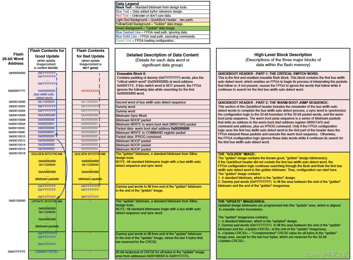
下图所示为 BPI Flash 的 QuickBoot存储映射示例:
- 第一列(最左侧)为 Good Update Bitstream情况
- 第二列为Bad Update bitstream情形
- 第三列为Flash 各Segment或地址内数据详细说明
- 第四列为Flash 对应的QuickBoot Flash模型中的部分
SPI Flash
3.3 Bitstream Image 大小与Flash存储大小选择
- Flash存储至少要大于Line 10的结果;
- 每个Bitstream image的大小要大于line 8的结果
4. QuickBoot参考设计实现指南
待续…
参考
- https://docs.xilinx.com/v/u/en-US/xapp1081-quickboot-remote-update


