文章目录
- 前言
- C mex文件
- mdlInitializeSizes
- mdlInitializeSampleTimes
- mdlOutputs
- mdlTerminate
- mdlRTW
- c文件结尾
- 编译c文件
- tlc文件
- Start函数
- Outputs函数
- 模型及生成的代码
- 总结
前言
在很早的时候,做过一些Simulink自定义硬件驱动库的相关探索,但是后面没有继续更新下去了。现在有空打算再重新整理一下。本文接着之前的那篇文章继续编写DO的C mex函数和tlc文件
C mex文件
首先配置s-function名称和level
#define S_FUNCTION_NAME  s12xep_dio_dout
#define S_FUNCTION_LEVEL 2
该名称需要与之前设计界面时填入的名称保持一致
level配置为2,可以扩展的功能更多。
必须要包含simstruc.h头文件,以调用API函数及结构
/*
 * Need to include simstruc.h for the definition of the SimStruct and
 * its associated macro definitions.
 */
#include "simstruc.h"
定义参数枚举及获取参数的宏定义
/*
 *  DIOPORT_GROUP    - Port Group A/B
 *  BIT_NUM          - Bit Num for Control
 */

enum {
    DIOPORT_GROUP=0,
    BIT_NUM,
    N_PARAMS
};

#define DIOPORT(S)          (mxGetScalar(ssGetSFcnParam(S, DIOPORT_GROUP)))
#define BITARRAY_ARG(S)     (            ssGetSFcnParam(S, BIT_NUM))
这个宏定义和s-function中的参数对应,用来获取参数值
ssGetSFcnParam 获取指向控件中参数的指针, mxGetScalar获取指针指向地址的数值
mdlInitializeSizes
设置或获取输入和输出端口的数量、宽度以及一些其他信息
/* Function: mdlInitializeSizes ===============================================
 * Abstract:
 *   Initialize the sizes array
 */
static void mdlInitializeSizes(SimStruct *S)
{
    int nBits;

    /* Set and Check parameter count  */
    ssSetNumSFcnParams(S, N_PARAMS);
    if (ssGetNumSFcnParams(S) != ssGetSFcnParamsCount(S)) return;
    ssSetSFcnParamNotTunable(S, 0);//设置模块参数值在仿真过程中不可变
    ssSetSFcnParamNotTunable(S, 1);//设置模块参数值在仿真过程中不可变

    nBits  = mxGetNumberOfElements(BITNUM(S));//获取对象中元素个数

    /* Single input port of width equal to nBits */
    if (!ssSetNumInputPorts( S, 1)) return;//设置输入端口个数为1
    if (!ssSetNumOutputPorts(S, 1)) return;//设置输出端口个数为1


         ssSetInputPortWidth(    S, 0, nBits);
         ssSetInputPortDataType( S, 0, SS_BOOLEAN);
         ssSetOutputPortWidth(   S, 0, nBits);
         ssSetOutputPortDataType(S, 0, SS_BOOLEAN);


    ssSetInputPortRequiredContiguous(S, 0, 1);//设置输入端口号为0的端口输入值必须为连续
    ssSetInputPortDirectFeedThrough( S, 0, 1);//设置输入端口直接馈通状态
    /* No output port of width equal to nBits */

    /* sample times */
    ssSetNumSampleTimes(S, 1 );
    //其中numSampleTimes > 0。这告诉Simulink你的s函数有基于块的样本时间。
    //Simulink调用mdlInitializeSampleTimes,它反过来设置示例时间。
    /* options */
    ssSetOptions(S, (SS_OPTION_EXCEPTION_FREE_CODE |
                     SS_OPTION_DISALLOW_CONSTANT_SAMPLE_TIME));
    //SS_OPTION_DISALLOW_CONSTANT_SAMPLE_TIME 用于禁止S-Function块继承常数样例时间。
} /* end mdlInitializeSizes */
使用ssSetNumSFcnParams函数设置参数个数
使用ssGetNumSFcnParams获取参数个数,与界面中设置的参数个数校验
使用ssSetNumInputPorts函数设置输入端口个数
使用ssSetNumOutputPorts设置输出端口个数,0表示第一个端口
使用ssSetInputPortWidth设置输入端口的宽度,0表示第一个端口
使用ssSetInputPortDataType设置输入端口的数据类型,输出同理
使用ssSetNumSampleTimes设置采样时间个数,具体采样时间在后面配置
mdlInitializeSampleTimes
设置采样时间
/* Function: mdlInitializeSampleTimes =========================================
 * Abstract:
 *    Initialize the sample times array.
 */
static void mdlInitializeSampleTimes(SimStruct *S)
{
    ssSetSampleTime(S, 0, INHERITED_SAMPLE_TIME);//引用模型的采样时间
    ssSetOffsetTime(S, 0, 0.0);

} /* end mdlInitializeSampleTimes */
mdlOutputs
此处没有添加代码
/* Function: mdlOutputs =======================================================
 * Abstract:
 *   Compute the outputs of the S-function.
 */
static void mdlOutputs(SimStruct *S, int_T tid)
{

} /* end mdlOutputs */
mdlTerminate
此处没有添加代码
/* Function: mdlTerminate =====================================================
 * Abstract:
 *    Called when the simulation is terminated.
 */
static void mdlTerminate(SimStruct *S)
{
} /* end mdlTerminate */
mdlRTW
在函数 mdlRTW 中设置模块参数,模块 tlc描述文件通过获取模块参数值来生成不同的模块代码
#define MDL_RTW
static void mdlRTW(SimStruct *S)
{
    uint8_T   dioPort     = (uint8_T) DIOPORT(S);
    uint16_T *bits        = (uint16_T *) mxGetData(BITNUM(S));

    /* Write out parameters for this block.*/
    if (!ssWriteRTWParamSettings(S, 2,
                                 SSWRITE_VALUE_DTYPE_NUM,"DIOPort",
                                 &dioPort,DTINFO(SS_UINT8, COMPLEX_NO),

                                 SSWRITE_VALUE_DTYPE_VECT, "Bits",
                                 bits,
                                 mxGetNumberOfElements(BITNUM(S)),
                                 DTINFO(SS_UINT16, COMPLEX_NO)
                                 )) {
        return; /* An error occurred which will be reported by SL */
    }
}
ssWriteRTWParamSettings函数的用法如下:
int_T ssWriteRTWParameters(SimStruct *S, int_T nParams, int_T
paramType, const char_T *paramName, const char_T *stringInfo,
...)
nParams表示需要传递的参数个数,paramType表示参数类型,paramName表示参数名称,stringInfo一般省略。
此处通过RTW传递数据给TLC,一个传递两个参数,第一个数据为Uint8类型的数值,表示PORT A/B的索引,注意此处传递的为地址
第二个数据为bit位置,传递的是数据向量,有三个参数,第一个参数为首地址,第二个参数为长度,第三个参数为数据类型
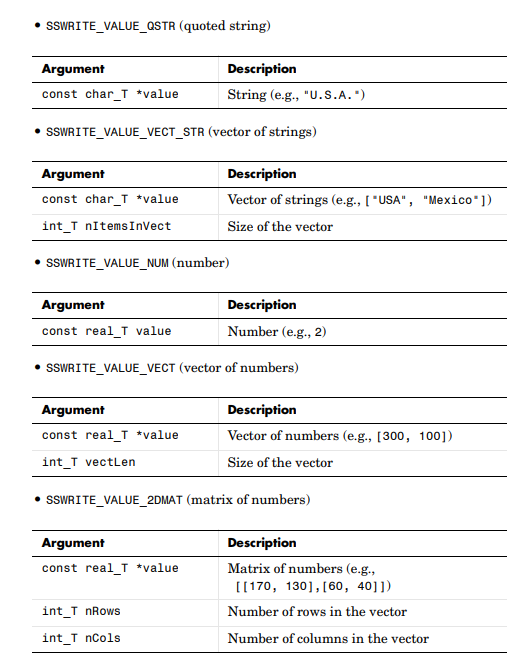
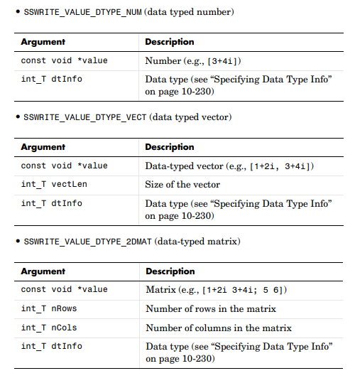
具体的paramType参数类型见下表:

c文件结尾
/*==============================================*
* Enforce use of inlined S-function             *
* (e.g. must have TLC file s12xep_dio_dout.tlc) *
*===============================================*/

#ifdef    MATLAB_MEX_FILE  /* Is this file being compiled as a MEX-file?    */
# include "simulink.c"     /* MEX-file interface mechanism                  */
#else                      /* Prevent usage by RTW if TLC file is not found */
# error "Attempted use non-inlined S-function s12xep_dio_dout.c"
#endif
结尾必须要加入该段,mex命令编译时,MATLAB_MEX_FILE自动被定义
编译c文件
编写好c文件后,使用mex命令编译c文件,可以命令行,也可以做成m脚本
mex s12xep_dio_dout.c

成功之后会生成.mexw64文件
tlc文件
tlc文件主要用来自定义生成的代码
%implements s12xep_dio_dout "C"
使用implements指定TLC语言类型,此处设置为C语言
%include "driver_utils.tlc"
该TLC文件中包含了一些公用的文件
Start函数
%% Function: Start ==========================================================
%%
%% Purpose:
%%      Port A/B Digital Input initialization code.
%%
%function Start(block, system) Output

    /* S-Function "s12xep_dio_dout" initialization Block: %<Name> */
    %%
    %% Select DIO Port A or Port B and enable the selected Bits
    %assign nPars       = SIZE(SFcnParamSettings.Bits,1)
    %assign port = getPort(SFcnParamSettings.DIOPort)
    %assign portId = CAST("Number", SFcnParamSettings.DIOPort)
    %assign nextChannel = 0
    %%

    %if ISEQUAL(portId,1)
          %% Configure Pins 0-3 of PORTA as outputs.
          %assign ddr = "DDRA"
    %else
          %assign ddr = "DDRB"
    %endif

      %foreach idx=nPars
        %assign bitIdx = CAST("Number",SFcnParamSettings.Bits[idx])
        %<ddr> =  %<ddr>  |  (0x1 << %<bitIdx>);  /* Select bit to be output */
        %<port> = %<port> | (0x1 << %<bitIdx>); /* Initial state */
        %assign nextChannel = nextChannel+1
      %endforeach


%endfunction
通过SIZE函数获取bit个数,此处只可能为1
通过getPort函数获取PORT名称,此处为PORTA或PORTB
通过CAST函数获取对应PORT参数中的Number,应该是从1开始的。
通过DDRA/B对应bit设置为1确定输出方向,通过PORTA/B配置输出电平高低,此处默认高电平
Outputs函数
%% Function: Outputs ==========================================================
%%
%% Purpose:
%%      Code generation rules for mdlOutputs function.
%%
%function Outputs(block, system) Output

    /* S-Function "s12xep_dio_dout" Block: %<Name> */

    %assign port        = getPort(SFcnParamSettings.DIOPort)
    %assign nPars       = SIZE(SFcnParamSettings.Bits, 1)
    %assign nextChannel = 0
    %%

      %foreach idx=nPars
        %assign u      = LibBlockInputSignal(0, "", "", %<nextChannel>)
        %assign bitIdx = CAST("Number",SFcnParamSettings.Bits[idx])
        %<port> = (%<port> & ~(1 << %<bitIdx>)) | ((%<u>) << %<bitIdx>); /* Clear the bit and set it to the input val */
        %assign nextChannel = nextChannel+1
    %endforeach


%%
%endfunction
通过LibBlockInputSignal获取输入参数的值,然后对对应的bit进行set
模型及生成的代码
增加一个DO模块,实际放到1000ms task中运行,关于task的建立后面再讲

初始化:
  /* S-Function "s12xep_dio_dout" initialization Block: <S1>/DO1 */
  DDRB = DDRB | (0x1 << 1);            /* Select bit to be output */
  PORTB = PORTB | (0x1 << 1);          /* Initial state */
实际运行函数:
void
 task_1000ms(void)
{
  /* Output and update for function-call system: '<Root>/Function-Call Subsystem' */

  /* Delay: '<S1>/Delay' */
  LED_value = tsk_test_DW.Delay_DSTATE;

  /* S-Function (s12xep_dio_dout): '<S1>/DO' */

  /* S-Function "s12xep_dio_dout" Block: <S1>/DO */
  PORTB = (PORTB & ~(1 << 1)) | ((LED_value) << 1);
                                 /* Clear the bit and set it to the input val */


  /* Update for Delay: '<S1>/Delay' incorporates:
   *  Logic: '<S1>/Logical Operator'
   */
  tsk_test_DW.Delay_DSTATE = !LED_value;
}
总结
以上,一个简单的自定义DO输出硬件驱动库就完成了。后面有空会更新其他模块。

