时钟
时钟是具有周期性的脉冲信号,最常用的是占空比50%的方波。
时钟是单片机的脉搏。
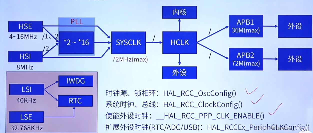
时钟树
- HSE:高速外部振荡器,4~16MHz,(晶体,陶瓷)
- LSE:低速外部振荡器,32.768KHz,(晶体,陶瓷)
- HSI:高速内部振荡器,8MHz,(RC)
- LSI:低速内部振荡器,40KHz,(RC)

外部高速振荡器

外部低速振荡器 - 外部振荡器需要外部接晶振(成本高),内部振荡器不需要。
- 外部振荡器准确性要高一些,所以有外部的时候一般选择外部。
STM32时钟树简图
MCO:对外部输出时钟的通道
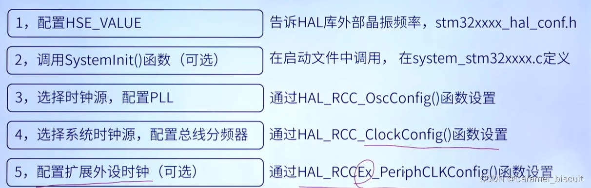
配置系统时钟步骤
外设时钟使能和失能
我们要使用某个外设,必须先使能该外设时钟!!!
比如:__HAL_RCC_GPIOA_CLK_ENABLE();
禁止:__HAL_RCC_GPIOA_CLK_DISABLE();
HAL库RCC
HAL库中的RCC(Reset and Clock Control)模块是用来控制各种时钟源和时钟分频器的模块,它提供了控制系统时钟频率和各种外设时钟的功能。
在HAL库中,RCC模块可以通过以下几个函数进行控制:
-
void HAL_RCC_OscConfig(RCC_OscInitTypeDef *RCC_OscInitStruct): 这个函数用来配置系统时钟源和时钟分频器。通过指定不同的参数,我们可以选择使用内部晶振、外部晶振或其他时钟源,并设置相应的时钟分频。 -
void HAL_RCC_ClockConfig(RCC_ClkInitTypeDef *RCC_ClkInitStruct, uint32_t FLatency): 这个函数用来配置各个外设的时钟源和分频。我们可以通过指定不同的参数,为不同的外设配置相应的时钟源和分频。 -
void HAL_RCC_MCOConfig(uint32_t RCC_MCOx, uint32_t RCC_MCOSource, uint32_t RCC_MCODiv): 这个函数用来配置MCU的主时钟输出(MCO)。我们可以通过指定不同的参数,选择输出不同的时钟源(例如系统时钟源、外部时钟源等)和相应的分频。
在使用RCC模块进行时钟控制时,需要特别注意一些细节,比如时钟分频的设置、时钟源与时钟分频的兼容性等等。因此,我们需要仔细研究数据手册和HAL库的API文档,才能正确地使用RCC模块进行时钟控制。
HAL_RCC_OscConfig()函数
HAL_StatusTypeDef HAL_RCC_OscConfig(RCC_OscInitTypeDef *RCC_OscInitStruct)
typedef struct
{
  uint32_t OscillatorType;       /*!< The oscillators to be configured.
                                       This parameter can be a value of @ref RCC_Oscillator_Type */

#if defined(STM32F105xC) || defined(STM32F107xC)
  uint32_t Prediv1Source;       /*!<  The Prediv1 source value.
                                       This parameter can be a value of @ref RCCEx_Prediv1_Source */
#endif /* STM32F105xC || STM32F107xC */

  uint32_t HSEState;              /*!< The new state of the HSE.
                                       This parameter can be a value of @ref RCC_HSE_Config */

  uint32_t HSEPredivValue;       /*!<  The Prediv1 factor value (named PREDIV1 or PLLXTPRE in RM)
                                       This parameter can be a value of @ref RCCEx_Prediv1_Factor */

  uint32_t LSEState;              /*!<  The new state of the LSE.
                                        This parameter can be a value of @ref RCC_LSE_Config */

  uint32_t HSIState;              /*!< The new state of the HSI.
                                       This parameter can be a value of @ref RCC_HSI_Config */

  uint32_t HSICalibrationValue;   /*!< The HSI calibration trimming value (default is RCC_HSICALIBRATION_DEFAULT).
                                       This parameter must be a number between Min_Data = 0x00 and Max_Data = 0x1F */

  uint32_t LSIState;              /*!<  The new state of the LSI.
                                        This parameter can be a value of @ref RCC_LSI_Config */

  RCC_PLLInitTypeDef PLL;         /*!< PLL structure parameters */

#if defined(STM32F105xC) || defined(STM32F107xC)
  RCC_PLL2InitTypeDef PLL2;         /*!< PLL2 structure parameters */
#endif /* STM32F105xC || STM32F107xC */
} RCC_OscInitTypeDef;
- OscillatorType:需要配置的振荡器
- HSIState:高速内部振荡器的状态
- HSICalibrationValue:HSI校准值
- PLL:PLL结构体
/**
  * @brief  RCC PLL configuration structure definition
  */
typedef struct
{
  uint32_t PLLState;      /*!< PLLState: The new state of the PLL.
                              This parameter can be a value of @ref RCC_PLL_Config */

  uint32_t PLLSource;     /*!< PLLSource: PLL entry clock source.
                              This parameter must be a value of @ref RCC_PLL_Clock_Source */

  uint32_t PLLMUL;        /*!< PLLMUL: Multiplication factor for PLL VCO input clock
                              This parameter must be a value of @ref RCCEx_PLL_Multiplication_Factor */
} RCC_PLLInitTypeDef;
HAL_StatusTypeDef HAL_RCC_ClockConfig(RCC_ClkInitTypeDef  *RCC_ClkInitStruct, uint32_t FLatency)
{
  uint32_t tickstart;

  /* Check Null pointer */
  if (RCC_ClkInitStruct == NULL)
  {
    return HAL_ERROR;
  }

  /* Check the parameters */
  assert_param(IS_RCC_CLOCKTYPE(RCC_ClkInitStruct->ClockType));
  assert_param(IS_FLASH_LATENCY(FLatency));

  /* To correctly read data from FLASH memory, the number of wait states (LATENCY)
  must be correctly programmed according to the frequency of the CPU clock
    (HCLK) of the device. */

#if defined(FLASH_ACR_LATENCY)
  /* Increasing the number of wait states because of higher CPU frequency */
  if (FLatency > __HAL_FLASH_GET_LATENCY())
  {
    /* Program the new number of wait states to the LATENCY bits in the FLASH_ACR register */
    __HAL_FLASH_SET_LATENCY(FLatency);

    /* Check that the new number of wait states is taken into account to access the Flash
    memory by reading the FLASH_ACR register */
    if (__HAL_FLASH_GET_LATENCY() != FLatency)
  {
    return HAL_ERROR;
  }
}

#endif /* FLASH_ACR_LATENCY */
/*-------------------------- HCLK Configuration --------------------------*/
if (((RCC_ClkInitStruct->ClockType) & RCC_CLOCKTYPE_HCLK) == RCC_CLOCKTYPE_HCLK)
  {
    /* Set the highest APBx dividers in order to ensure that we do not go through
    a non-spec phase whatever we decrease or increase HCLK. */
    if (((RCC_ClkInitStruct->ClockType) & RCC_CLOCKTYPE_PCLK1) == RCC_CLOCKTYPE_PCLK1)
    {
      MODIFY_REG(RCC->CFGR, RCC_CFGR_PPRE1, RCC_HCLK_DIV16);
    }

    if (((RCC_ClkInitStruct->ClockType) & RCC_CLOCKTYPE_PCLK2) == RCC_CLOCKTYPE_PCLK2)
    {
      MODIFY_REG(RCC->CFGR, RCC_CFGR_PPRE2, (RCC_HCLK_DIV16 << 3));
    }

    /* Set the new HCLK clock divider */
    assert_param(IS_RCC_HCLK(RCC_ClkInitStruct->AHBCLKDivider));
    MODIFY_REG(RCC->CFGR, RCC_CFGR_HPRE, RCC_ClkInitStruct->AHBCLKDivider);
  }

  /*------------------------- SYSCLK Configuration ---------------------------*/
  if (((RCC_ClkInitStruct->ClockType) & RCC_CLOCKTYPE_SYSCLK) == RCC_CLOCKTYPE_SYSCLK)
  {
    assert_param(IS_RCC_SYSCLKSOURCE(RCC_ClkInitStruct->SYSCLKSource));

    /* HSE is selected as System Clock Source */
    if (RCC_ClkInitStruct->SYSCLKSource == RCC_SYSCLKSOURCE_HSE)
    {
      /* Check the HSE ready flag */
      if (__HAL_RCC_GET_FLAG(RCC_FLAG_HSERDY) == RESET)
      {
        return HAL_ERROR;
      }
    }
    /* PLL is selected as System Clock Source */
    else if (RCC_ClkInitStruct->SYSCLKSource == RCC_SYSCLKSOURCE_PLLCLK)
    {
      /* Check the PLL ready flag */
      if (__HAL_RCC_GET_FLAG(RCC_FLAG_PLLRDY) == RESET)
      {
        return HAL_ERROR;
      }
    }
    /* HSI is selected as System Clock Source */
    else
    {
      /* Check the HSI ready flag */
      if (__HAL_RCC_GET_FLAG(RCC_FLAG_HSIRDY) == RESET)
      {
        return HAL_ERROR;
      }
    }
    __HAL_RCC_SYSCLK_CONFIG(RCC_ClkInitStruct->SYSCLKSource);

    /* Get Start Tick */
    tickstart = HAL_GetTick();

    while (__HAL_RCC_GET_SYSCLK_SOURCE() != (RCC_ClkInitStruct->SYSCLKSource << RCC_CFGR_SWS_Pos))
    {
      if ((HAL_GetTick() - tickstart) > CLOCKSWITCH_TIMEOUT_VALUE)
      {
        return HAL_TIMEOUT;
      }
    }
  }

#if defined(FLASH_ACR_LATENCY)
  /* Decreasing the number of wait states because of lower CPU frequency */
  if (FLatency < __HAL_FLASH_GET_LATENCY())
  {
    /* Program the new number of wait states to the LATENCY bits in the FLASH_ACR register */
    __HAL_FLASH_SET_LATENCY(FLatency);

    /* Check that the new number of wait states is taken into account to access the Flash
    memory by reading the FLASH_ACR register */
    if (__HAL_FLASH_GET_LATENCY() != FLatency)
  {
    return HAL_ERROR;
  }
}
#endif /* FLASH_ACR_LATENCY */

/*-------------------------- PCLK1 Configuration ---------------------------*/
if (((RCC_ClkInitStruct->ClockType) & RCC_CLOCKTYPE_PCLK1) == RCC_CLOCKTYPE_PCLK1)
  {
    assert_param(IS_RCC_PCLK(RCC_ClkInitStruct->APB1CLKDivider));
    MODIFY_REG(RCC->CFGR, RCC_CFGR_PPRE1, RCC_ClkInitStruct->APB1CLKDivider);
  }

  /*-------------------------- PCLK2 Configuration ---------------------------*/
  if (((RCC_ClkInitStruct->ClockType) & RCC_CLOCKTYPE_PCLK2) == RCC_CLOCKTYPE_PCLK2)
  {
    assert_param(IS_RCC_PCLK(RCC_ClkInitStruct->APB2CLKDivider));
    MODIFY_REG(RCC->CFGR, RCC_CFGR_PPRE2, ((RCC_ClkInitStruct->APB2CLKDivider) << 3));
  }

  /* Update the SystemCoreClock global variable */
  SystemCoreClock = HAL_RCC_GetSysClockFreq() >> AHBPrescTable[(RCC->CFGR & RCC_CFGR_HPRE) >> RCC_CFGR_HPRE_Pos];

  /* Configure the source of time base considering new system clocks settings*/
  HAL_InitTick(uwTickPrio);

  return HAL_OK;
}
typedef struct
{
  uint32_t ClockType;             /*!< The clock to be configured.
                                       This parameter can be a value of @ref RCC_System_Clock_Type */

  uint32_t SYSCLKSource;          /*!< The clock source (SYSCLKS) used as system clock.
                                       This parameter can be a value of @ref RCC_System_Clock_Source */

  uint32_t AHBCLKDivider;         /*!< The AHB clock (HCLK) divider. This clock is derived from the system clock (SYSCLK).
                                       This parameter can be a value of @ref RCC_AHB_Clock_Source */

  uint32_t APB1CLKDivider;        /*!< The APB1 clock (PCLK1) divider. This clock is derived from the AHB clock (HCLK).
                                       This parameter can be a value of @ref RCC_APB1_APB2_Clock_Source */

  uint32_t APB2CLKDivider;        /*!< The APB2 clock (PCLK2) divider. This clock is derived from the AHB clock (HCLK).
                                       This parameter can be a value of @ref RCC_APB1_APB2_Clock_Source */
} RCC_ClkInitTypeDef;
RCC_ClkInitStruct.ClockType = RCC_CLOCKTYPE_HCLK|RCC_CLOCKTYPE_SYSCLK
                              |RCC_CLOCKTYPE_PCLK1|RCC_CLOCKTYPE_PCLK2;
  RCC_ClkInitStruct.SYSCLKSource = RCC_SYSCLKSOURCE_HSI;
  RCC_ClkInitStruct.AHBCLKDivider = RCC_SYSCLK_DIV1;
  RCC_ClkInitStruct.APB1CLKDivider = RCC_HCLK_DIV1;
  RCC_ClkInitStruct.APB2CLKDivider = RCC_HCLK_DIV1;

  if (HAL_RCC_ClockConfig(&RCC_ClkInitStruct, FLASH_LATENCY_0) != HAL_OK)
  {
    Error_Handler();
  }
#define FLASH_LATENCY_0            0x00000000U               /*!< FLASH Zero Latency cycle FLASH 0个等待周期 */
#define FLASH_LATENCY_1            FLASH_ACR_LATENCY_0       /*!< FLASH One Latency cycle */
#define FLASH_LATENCY_2            FLASH_ACR_LATENCY_1       /*!< FLASH Two Latency cycles */
LATENCY:时延
SYSCLK周期与闪存访问时间的比例
- 000:零等待状态,当0<SYSCLK≤24MHz
- 001:一个等待状态,当24MHz<SYSCLK≤48MHz
- 010:两个等待状态,当48MHz<SYSCLK≤72MHz


![强化学习从基础到进阶-案例与实践[4]:深度Q网络-DQN、double DQN、经验回放、rainbow、分布式DQN](../img/ch8/8.3.png)