GRE over IPsec VPN配置
【实验目的】
- 理解GRE Tunnel的概念。
- 理解GRE over IPsec VPN的概念。
- 掌握GRE Tunnel的配置。
- 掌握GRE over IPsec VPN的配置。
- 验证配置。
【实验拓扑】
实验拓扑如下图所示。
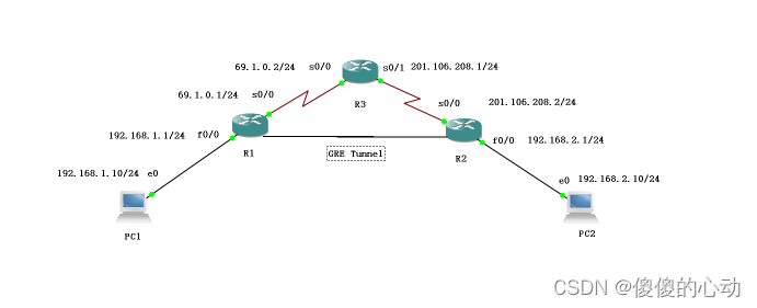
实验拓扑
设备参数表如下表所示。
设备参数表
| 设备 | 接口 | IP地址 | 子网掩码 | 默认网关 |
| R1 | s0/0 | 69.1.0.1 | 255.255.255.0 | N/A |
| g0/0/0 | 192.168.1.1 | 255.255.255.0 | N/A | |
| R3 | s0/0 | 69.1.0.2 | 255.255.255.0 | N/A |
| S0/1 | 201.106.208.1 | 255.255.255.0 | N/A | |
| R2 | s0/0 | 201.106.208.2 | 255.255.255.0 | N/A |
| g0/0/0 | 192.168.2.1 | 255.255.255.0 | N/A | |
| PC1 | g0/0/0 | 192.168.1.100 | 255.255.255.0 | 192.168.1.1 |
| PC2 | g0/0/0 | 192.168.2.100 | 255.255.255.0 | 192.168.2.1 |
【实验内容】
1.IP地址与路由配置
//R1
enable

conf t

hostname R1

interface g0/0/0

ip address 192.168.1.1 255.255.255.0

no shutdown

exit

interface s0/0

ip address 69.1.0.1 255.255.255.0

no shutdown

exit
//R3
conf t

hostname R3

interface s0/0

ip address 69.1.0.2 255.255.255.0

no shutdown

interface s0/1

ip add 201.106.208.1 255.255.255.0

no shutdown

exit
//R2
enable

conf t

hostname R2

interface s0/0

ip address 201.106.208.2 255.255.255.0

no shutdown

exit

interface g0/0/0

ip add 192.168.2.1 255.255.255.0

no shutdown

exit
2.IP地址与路由配置
在路由器R1、R2上配置IP地址,测试各直连链路的连通性,并配置如下路由:
//R1
ip route 0.0.0.0 0.0.0.0 s0/0
//R2
ip route 0.0.0.0 0.0.0.0 s0/0
测试从R1能否ping通R2的公网接口
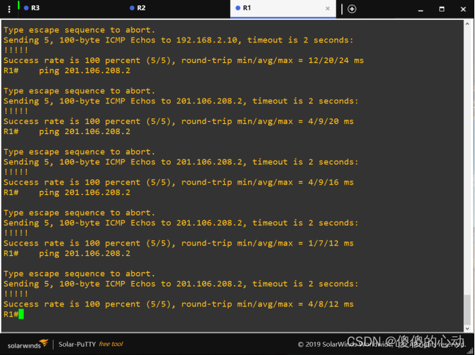
在R1上追踪路由
R1#traceroute 192.168.2.10
Type escape sequence to abort.
Tracing the route to 192.168.2.10
1 69.1.0.2 0 msec 0 msec 4 msec
2 201.106.208.2 44 msec 4 msec 8 msec
3 192.168.2.10 20 msec 8 msec 24 msec
R1#
3.配置GRE Tunnel
(1)R1的配置
conf t
interface Tunnel0
//创建Tunnel接口,编号为0,编号本地有效
tunnel mode gre ip
//配置Tunnel类型为IPv4 GRE Tunnel
ip address 172.16.0.1 255.255.255.0
//配置Tunnel接口的IP地址,隧道建立后,可以把该隧道看成一条专线
tunnel source Serial0/0
//配置Tunnel接口,路由器将以此接口地址作为Tunnel的源地址封装VPN数据包,也可以直接输入源地址
tunnel destination 201.106.208.2
//配置Tunnel的目的地址,路由器将以此目的地址作为Tunnel的目的地址封装VPN数据包
(2)R2的配置
conf t

interface Tunnel0

tunnel mode gre ip

ip address 172.16.0.2 255.255.255.0

tunnel source Serial0/0

tunnel destination 69.1.0.1
以上配置完成后,通过ping测试确保隧道两端可达。
R2#ping 172.16.0.1
Type escape sequence to abort.
Sending 5, 100-byte ICMP Echos to 172.16.0.1, timeout is 2 seconds:
!!!!!
Success rate is 100 percent (5/5), round-trip min/avg/max = 8/17/32 ms
R2#
4.配置GRE over IPSEC
(1)R1的配置
conf t

crypto isakmp enable

crypto isakmp policy 10

encr 3des

authentication pre-share

group 5

crypto isakmp key 6 cisco address 201.106.208.2

crypto ipsec transform-set TRAN esp-3des esp-sha-hmac

ip access-list extended Gol

permit gre host 69.1.0.1 host 201.106.208.2
//此处应注意,应匹配GRE流量(GRE over IPSec VPN将所有GRE隧道的流量都进行加密),源地址和目的地址应是IPSec物理源接口和物理目的接口的IP地址
crypto map MAP 10 ipsec-isakmp

set peer 201.106.208.2

set transform-set TRAN

match address Gol

interface Serial0/0

crypto map MAP
//GRE over IPSec VPN的加密图要应用在物理源接口上
(2)R2的配置
conf t

crypto isakmp enable

crypto isakmp policy 10

encr 3des

authentication pre-share

group 5

crypto isakmp key 6 cisco address 69.1.0.1

crypto ipsec transform-set TRAN esp-3des esp-sha-hmac

ip access-list extended Gol

permit gre host 201.106.208.2 host 69.1.0.1

crypto map MAP 10 ipsec-isakmp

set peer 69.1.0.1

set transform-set TRAN

match address Gol

interface Serial0/0

crypto map MAP
5.配置隧道间路由
//R1
ip route 192.168.2.0 255.255.255.0 Tunnel0
//R2
ip route 192.168.1.0 255.255.255.0 Tunnel0
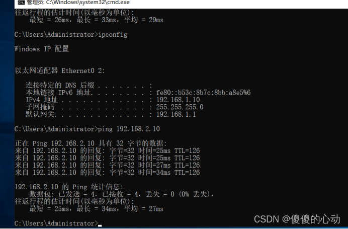
测试从R1的内网能否ping通R2的内网
6.实验调试
(1)测试两端网络通信
首先检查路由表,输出如下:
R1#show ip route
Codes: C - connected, S - static, R - RIP, M - mobile, B - BGP
D - EIGRP, EX - EIGRP external, O - OSPF, IA - OSPF inter area
N1 - OSPF NSSA external type 1, N2 - OSPF NSSA external type 2
E1 - OSPF external type 1, E2 - OSPF external type 2
i - IS-IS, su - IS-IS summary, L1 - IS-IS level-1, L2 - IS-IS level-2
ia - IS-IS inter area, * - candidate default, U - per-user static route
o - ODR, P - periodic downloaded static route
Gateway of last resort is 0.0.0.0 to network 0.0.0.0
69.0.0.0/24 is subnetted, 1 subnets
C 69.1.0.0 is directly connected, Serial0/0
172.16.0.0/24 is subnetted, 1 subnets
C 172.16.0.0 is directly connected, Tunnel0
C 192.168.1.0/24 is directly connected, FastEthernet0/0
S 192.168.2.0/24 is directly connected, Tunnel0
S* 0.0.0.0/0 is directly connected, Serial0/0
R1#
从路由器R1上ping通R2局域网网段,触发IPSec隧道建立。
R1#ping 192.168.2.0
Type escape sequence to abort.
Sending 5, 100-byte ICMP Echos to 192.168.2.0, timeout is 2 seconds:
.!!!!
//第一个ICMP数据包触发IPsec建立,因此不可达
Success rate is 100 percent (5/5), round-trip min/avg/max = 12/13/16 ms
R1#
(2)检查IPSec相关情况
首先检查路由表,输出如下:
R1#show crypto ipsec sa
interface: Serial0/0
Crypto map tag: MAP, local addr 69.1.0.1
protected vrf: (none)
local ident (addr/mask/prot/port): (69.1.0.1/255.255.255.255/47/0)
remote ident (addr/mask/prot/port): (201.106.208.2/255.255.255.255/47/0)
current_peer 201.106.208.2 port 500
PERMIT, flags={origin_is_acl,}
#pkts encaps: 21, #pkts encrypt: 21, #pkts digest: 21
#pkts decaps: 21, #pkts decrypt: 21, #pkts verify: 21
#pkts compressed: 0, #pkts decompressed: 0
#pkts not compressed: 0, #pkts compr. failed: 0
#pkts not decompressed: 0, #pkts decompress failed: 0
#send errors 1, #recv errors 0
//已经有IPSec相关数据包
local crypto endpt.: 69.1.0.1, remote crypto endpt.: 201.106.208.2
path mtu 1500, ip mtu 1500, ip mtu idb Serial0/0
current outbound spi: 0x386E4AE3(946752227)
inbound esp sas:
spi: 0x8384871E(2206500638)
transform: esp-3des esp-sha-hmac ,
in use settings ={Tunnel, }
conn id: 2001, flow_id: SW:1, crypto map: MAP
sa timing: remaining key lifetime (k/sec): (4580078/3181)
IV size: 8 bytes
replay detection support: Y
Status: ACTIVE
inbound ah sas:
inbound pcp sas:
outbound esp sas:
spi: 0x386E4AE3(946752227)
transform: esp-3des esp-sha-hmac ,
in use settings ={Tunnel, }
conn id: 2002, flow_id: SW:2, crypto map: MAP
sa timing: remaining key lifetime (k/sec): (4580078/3179)
IV size: 8 bytes
replay detection support: Y
Status: ACTIVE
outbound ah sas:
outbound pcp sas:
R1#
(3)追踪路由
在R1上面追踪路由,输出如下:
R1#traceroute 192.168.2.10
Type escape sequence to abort.
Tracing the route to 192.168.2.10
1 172.16.0.2 24 msec 12 msec 12 msec
2 192.168.2.10 16 msec * 20 msec
R1#
//发现只有两条路由了
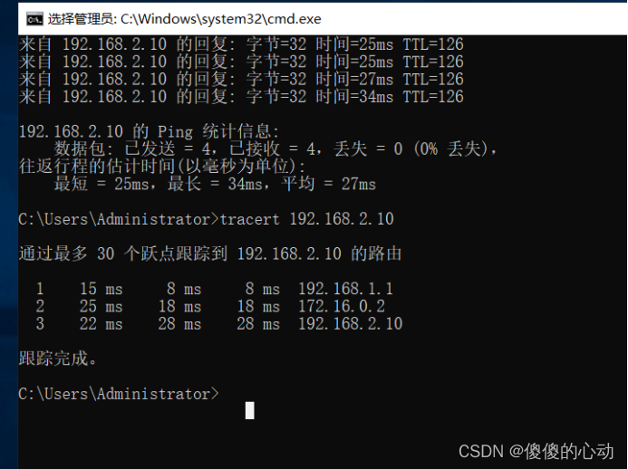
在PC1上面追踪路由,输出如下:
记住,进步是一步一步来的。庆祝每一个小小的胜利,并继续朝着你的目标前进。


