目录
1、TIMER计时器调试
2、UART串口调试
2.1 核传输
2.2 EDMA传输
1、TIMER计时器调试
The TMS320C6678 device has sixteen 64-bit timers in total. Timer0 through Timer7 are dedicated to each of the eight CorePacs as a watchdog timer and can also be used as general-purpose timers. Each of the other eight timers can also be configured as a general-purpose timer only, with each timer programmed as a 64-bit timer or as two separate 32-bit timers.
The timer can be configured in one of three modes using the timer mode (TIMMODE) bits in the timer global control register (TGCR):
• 64-bit general-purpose (GP) timer
• dual 32-bit timers (TIMLO and TIMHI)
• watchdog timer.
定时器的初始化,及其中断是关键。配置的寄存器主要是TCR和TGCR。
typedef struct  {
	int timer_num; 				/*select one timer*/
	TTimerMode timerMode; 		/*select function of the timer*/
	unsigned long long period; 	/*in the unit of DSP core clock/6*/
	unsigned long long reload_period; 	/*the reload value of period*/
	int pulseWidth; 			/*pulse width between 0~3*/
}Timer64_Config;//需配置的相关参数
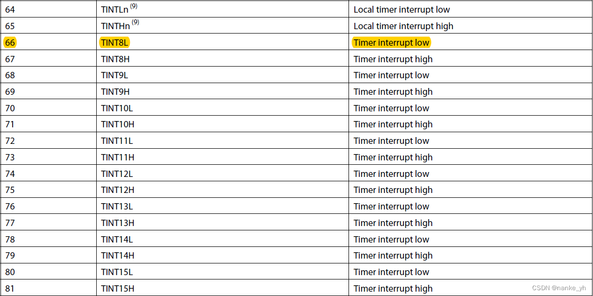
中断挂载参考表:
2、UART串口调试
The following steps are required to initialize the UART:
1. Perform the necessary device pin multiplexing setup (see the device-specific data manual).
2. Set the desired baud rate by writing the appropriate clock divisor values to the divisor latch registers (DLL and DLH).
3. If the FIFOs will be used, select the desired trigger level and enable the FIFOs by writing the appropriate values to the FIFO control register (FCR). The FIFOEN bit in FCR must be set first, before the other bits in FCR are configured.
4. Choose the desired protocol settings by writing the appropriate values to the line control register (LCR).
5. If autoflow control is desired, write appropriate values to the modem control register (MCR). Note that all UARTs do not support autoflow control, see the device-specific data manual for supported features.
6. Choose the desired response to emulation suspend events by configuring the
FREE bit and enable the UART by setting the UTRST and URRST bits in the power and emulation management register (PWREMU_MGMT).
串口的数据传输存在两种形式:UART_USE_CORE_TO_TX,UART_USE_EDMA_TO_TX。一种是通过核的方式,直接数据传输,另一种是通过EDMA的方式进行数据的传递,再通过串口线打印和显示。
这两种均需要对其进行配置,不同在于EDMA的还需要另外配置EDMA。
gUARTCfg.baudRate = baudRate;//设置串口波特率

gUARTCfg.DSP_Core_Speed_Hz = gDSP_Core_Speed_Hz;//确认核时钟

gUARTCfg.dataLen = DATA_LEN_8BIT;//8bit数据

gUARTCfg.parityMode = PARITY_DISABLE;//无奇偶校验

gUARTCfg.stopMode = ONE_STOP_BIT;//一个停止位

gUARTCfg.autoFlow = AUTO_FLOW_DIS;

gUARTCfg.osmSel = OVER_SAMPLING_16X;

gUARTCfg.fifoRxTriBytes = TRIGGER_LEVEL_1BYTE;//fifo为1位

gUARTCfg.txMaster = txMaster;//edma或者核操作

gUARTCfg.bLoopBackEnable = bLoopBackEnable;//回环测试
2.1 核传输
该方式相对简单,只需要判读相应的FIFO寄存器LSR,是空还是满,在从缓存寄存器RBR中读取数据即可,另外配置好中断,即可实现串口的收发。(具体查看手册)
2.2 EDMA传输
该方式对EDMA的配置类同于EDMA3.那么其中断将是根据EDMA的中断表配置。
DSP篇--C6678功能调试系列之EDMA3调试_nanke_yh的博客-CSDN博客![]() https://blog.csdn.net/nanke_yh/article/details/128156123
https://blog.csdn.net/nanke_yh/article/details/128156123


![[附源码]计算机毕业设计springboot学分制环境下本科生学业预警帮扶系统](https://img-blog.csdnimg.cn/62a6f64ad23d4eb0b3bb4881f51e5164.png)

![[附源码]计算机毕业设计springboot兴达五金日杂批发商店管理系统](https://img-blog.csdnimg.cn/171d89aec3ef4248912a0dc089e77112.png)
