目录
1. 概要
2. 整体架构流程
3. 控制系统设计
3.1 Vision-based Human-Robot Interaction Control
3.2 Human Motion Estimation Approach
4. 实现方法及实验验证
4.1 System Implementation
4.2 Experimental Setup
4.3 Experimental Results
5. 小结
1. 概要
利用新型仿人双臂空中机械手实现更自然、更拟人化的作业交互,实现混合智能遥操作控制,仍然是一个亟待解决的问题。针对我们设计的新型空中双手机械手,提出了一种基于视觉的直观控制策略,重点是增强人机交互(HRI)和基于视觉的遥操作。这种创新的HRI控制策略近似于人类操作员的运动意图和机械手定位之间的复杂非线性映射函数。此外,使用KF算法融合了来自多个Kinect DK单元的鲁棒全身3D骨架跟踪,为空中机械手的遥操作控制服务。采用这种控制系统,双臂空中机械手可以与人类合作,灵活高效地执行双手任务。实验结果证明了所提出的基于视觉的骨架跟踪方法在航空机械手遥操作控制中促进人机协作交互的充分性和准确性。
最近,与环境进行物理交互的拟人化空中操纵器引起了学术界和工业界的极大兴趣。将拟人化操纵器与无人机集成在一起,使空中机器人能够与环境和物体进行交互,应用范围包括电力线基础设施检查[6]、建筑工地协助[7]、基于接触的安装[8]等。这些系统为人类执行具有挑战性或危险性的任务提供了灵活和动态的解决方案,特别是在难以到达或封闭的空间中。然而,在研究类人拟人化航空机械手技术及其应用时,复杂的动态配置和与环境的物理交互所带来的协调控制挑战是开发和应用的重要制约因素。因此,研究可以在这些复杂的动态航空机器人系统中快速部署的人在环控制策略,以实现高效和精确的操作,具有重大的研究和应用价值。
基于视觉的人机混合遥操作是一种人机交互系统,允许操作员通过视觉反馈控制远程机器人[9]。随着计算机视觉和人工智能技术的快速发展,基于视觉的遥操作技术近年来得到了广泛的关注和应用。已经进行了几项研究,以引入类人行为来提高人机协作任务的性能。Meng等人[5]提出了一种接触力控制框架来解决这个问题,其中使用逆动力学方法设计接触力控制器,并采用姿态前馈方法来提高力跟踪性能。开发了创新的航空机械手原型并进行了飞行实验,验证了提出的框架。此外,Sampedro等人[10]、Liang等人[3]、Malczyk等人[4]还研究了基于图像的视觉伺服与环境物理交互的相关方向以及航空机械手的接触力控制策略。在[11]和[12]中,来自不同运动捕捉系统的2D或3D骨架数据已被用于提高人体姿势跟踪性能。Liang等人[13]、Su等人[14]也研究了用于类人行为模仿的深度学习网络方法,以提高人机交互(HRI)的质量。
从现有的研究来看,基于视觉的人机混合遥操作在航空机器人系统中的研究很少,其中大部分是近年来开始的。我们提出了一种混合人机交互(HRI)控制系统来解决上述挑战。提出了一种基于人体3D骨架估计的人机交互界面,该界面允许人类用户在模拟和现实环境中与机器人交互并将运动传递给机器人。机器人手臂可以通过利用运动学冗余来实现仿人动作,而不是在末端执行器上进行类似人类的运动。实现了具有离散协同控制系统的航空机械手原型。最后,建立了实验场景,以提高所提出的基于视觉的航空机械手HRI控制方法的系统性能。
2. 整体架构流程
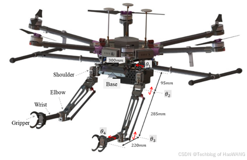
本文基于人体手臂的简化运动学模型,设计并开发了一种具有柔顺性和拟人化特征的仿人双臂空中机械手系统。整体结构采用仿生设计原理,左臂和右臂对称。为了满足空中机器人的有效载荷能力和续航能力需求,该原型的每个模块都经过模块化、紧凑和轻便的设计,便于无缝集成到空中机器人系统中。每个机械手都有一个4自由度结构,用于基于空中接触的操纵,并在肩部柔性关节中设计了一个紧凑的柔性机构。3D空中机械手原型如图1所示。

双臂的大小和比例以及肩宽与人类手臂相似。在这些关节中,肩部偏航和肩部俯仰是顺应性关节,关节结构包含一个顺应性机制。这种设计具有人形和低惯性的顺应性特征,便于模仿和复制拟人化双手技能[15]。柔性关节作为机械手结构中的一个轻质柔性单元,其设计合理性对机械手的稳定运动和接触安全起着重要作用[16]。
该系统集成了一个最大起飞重量为15公斤的多旋翼平台、两个4自由度空中机械手和高性能机载计算设备Jetson Xavier NX。此外,控制系统的软件架构采用分布式控制策略,使遥操作控制系统、空中机器人任务管理器和机器人手臂运动控制器在不同的计算设备上运行。这种分布式计算架构有助于降低机载侧的计算负载和功耗,这对提高系统的稳定性和可扩展性具有重要意义。同时,地面军事系统作为人机交互的遥操作控制和可视化终端,提供精细的操作控制和状态信息反馈,使地面操作员能够控制空中机械手稳定可靠地执行任务。此外,弹性驱动单元仅集成在肩关节和摆动关节中,以尽可能减轻整体重量。
3. 控制系统设计
3.1 Vision-based Human-Robot Interaction Control
Modeling and tracking the human body’s 3D skeleton is important in designing the vision-based HRI teleoperation controller. Figure 2 illustrates the joint locations and connections relative to the human body for the Azure Kinect method and OpenPose. In this study, we use the Azure Kinect human skeleton modeling method. The skeleton includes 32 joints, with the joint hierarchy flowing from the body's center to the extremities, and each connection (bone) links the parent joint with a child joint.

Figure 2. Human 3D skeleton and joint locations and connections definition. (a) Azure Kinect; (b) OpenPose.
An aerial dual-arm robot teleoperation control system was designed and developed based on the definition of the human body skeleton and the kinematic model of the humanoid dual-arm system. Figure 3 shows this control system mainly comprises three major components: the ground station human-in-the-loop teleoperation control platform, the human motion state estimator, and the compliant aerial robotic arm hardware platform.

Figure 3. The visual-guided teleoperation control architecture diagram for the aerial manipulator.
In this control framework, the ground station human-in-the-loop teleoperation control platform serves as the operational visual data processing unit, extracting the upper limb motion demonstration and fine gesture actions from two Kinect DK visual cameras and one RealSense D435i camera to produce color and depth images. The state estimator receives this human motion state image packets frame by frame to extract the 3D skeletal points of the upper limbs and arms. The designed vision-based state estimator fuses the skeletal motion information from multiple visual cameras into high-quality joint motion estimation data free from occlusion, noise, and jitter.
Subsequently, the joint controller of the aerial dual-arm robot receives the human joint motion data processed by the joint angle smoother, performing workspace remapping and joint servo control for the robotic arms. The control objective is to minimize the end-effector pose and joint angle deviations. Concurrently, a multi-agent distributed collaborative control and communication system was designed and developed, along with the ground station control equipment and the aerial dual-arm robot edge computing controller, to achieve natural human-robot interaction control and operational process visualization.
3.2 Human Motion Estimation Approach
To achieve human-like behavior on the designed aerial manipulator, the human arm is simplified as a rigid kinematic chain connected by three basic joints: shoulder joint, elbow joint, and wrist joint, as shown in Figure 2. Using multiple Kinect DKs, we can have the skeleton data of the human arm joints directly, including 32 joints in 3D positions relative to the camera coordinate. These joint angles are all in the joint space, as shown in Figure 4. When estimating the posture of the human arm, the elbow swivel angle is used to represent the lateral motion of the elbow joint. The intersection of the reference and arm planes defines this angle. However, because the developed 4-degree-of-freedom aerial robotic arm joints cannot fully mimic the joint configuration of the human arm, this angle is disregarded in the human motion estimator, focusing on the rotational angles of each joint.

Figure 4. Definition of the joint angle of the human arm using skeleton data.
4. 实现方法及实验验证
4.1 System Implementation
We implemented a prototype of the vision-based markerless full-body skeleton tracking system using multiple devices, two Kinect DK and one RealSense D435i. The system setup is shown in Figure 5. A graphic workstation(Intel Core i5-8400H at 4.2GHz, 16GB RAM, and NVIDIA GPU 1650) is applied as the server to drive the main 3D skeleton tracking and data fusion program. These visual devices are connected to the server computer via a USB 3.0 communication hub. The ground control station(GCS) is the human-control client that obtains the robot state information and publishes the control commands in real-time. When a foreground object blocks the view of part of a background object for one of the two cameras on a device, the occlusion will occur. Therefore, multiple Azure Kinect DK devices should be synchronized with one master and one subordinate device to reduce the occlusions. The master device's Sync Out port provides the triggering signal for the subordinate device's Sync In port through a 3.5-mm audio cable.

Figure 5. Multi-Kinect 3D skeleton state estimation system setup. (a)System architecture and main components diagram; (b) Experimental devices implementation.
The multiple Kinects are evenly placed in a semi-circle space with a radius of 2.5m, facing the center of the circle. With the setup, the tracking space of the system is shown in Figure 6. The RGB-D camera RealSense D435i is fixed at a lower height to detect operators' hand postures. The available tracking space is a hexagon with a long axis of 2.5 m (shown as the blue area), and the fine tracking space is a hexagon area with a 2.5-3.0 m diameter.

Figure 6. Tracking Space of the multi-kinect system.
4.2 Experimental Setup
To verify the efficiency of the proposed HRI method, human-robot telemanipulation for moving objects is implemented with comparative tests under two different scenarios: low stiffness mode and human-operated mode. As shown in Figure 7, the human operator moves the aerial robot arm via visual feedback from the Ground Control Station (GCS) and adapts the arm pose to move the objects to enable the aerial robot to imitate human motor adaptive behaviors through UDP communications between the host computer and the aerial manipulator.

Figure 7. Vision-guided teleoperation experimental devices for the dual-arm aerial manipulator.
4.3 Experimental Results
- Joint State Estimation Experiment Results
In this study, we employed the designed multi-kinect data fusion state estimator to estimate and analyze joint angles of the human body arm, focusing on three key aspects: response speed, motion tracking accuracy, and estimation smoothness. The experiment was divided into three stages of arm movements: the first involved shoulder swing and pitch movements during 10s ~ 30s, the second involved elbow flexion and extension during 30s ~ 50s, and the third involved combined movements of the shoulder and elbow joints during 50s ~ 80s. The experimental results can be seen in Figure 8.
First, the multi-Kinect state estimation system's average response time to changes in joint angles was 30 milliseconds, with the maximum response time not exceeding 50 milliseconds, similar to the estimator used by a single Kinect DK. This demonstrates high sensitivity and the ability to rapidly capture variations in joint angles. Second, the system exhibited an average tracking error of less than 5mm regarding motion-tracking accuracy, indicating that it can accurately reflect the changes in joint positions and angles. In this regard, the estimation accuracy of the single-kinect estimator is not as good as that after multi-kinect fusion. Finally, regarding motion estimation smoothness, analysis of the joint angle time-series data revealed that the system's output joint angle curves were highly smooth, suggesting that the system can avoid abrupt transitions and provide continuous and smooth motion trajectories.

Figure 8. Human joint position tracking results.
2. HRI Teleoperation Control Experiments
Participants stood before the visual equipment in this experiment, utilizing dual Kinect DK and D435i devices for human motion tracking and state estimation. The control system integrated gesture recognition algorithms, motion planning algorithms, and low-level control interfaces to achieve human-robot teleoperation control. Gesture recognition captured basic hand gestures, such as fist clenching and palm opening. These were then discretized into control input signals for the end-effector to execute grasping and placing tasks.

Figure 9. Image sequence of aerial manipulator pick and place operation experiment process.

Figure 10. The actuator state changes of the aerial manipulator joint actuators for the teleoperation test:(a) Joint Position and (b) Gripper State.
Figures 9 and 10 show that the robotic hand could achieve smooth motion trajectories during grasping and placing tasks, minimizing abrupt transitions and enhancing the naturalness and fluidity of operations. Then, regarding control accuracy, the system exhibited an average positional error of 1.5 millimeters, with the maximum positional error not exceeding 3 millimeters. This level of precision ensures accurate completion of grasping and placing tasks. The gesture recognition accuracy was more than 90%, with the end-effector state control response time being 30 milliseconds. These data indicate that the system efficiently and accurately recognizes operational gestures and responds swiftly, ensuring consistency between the robotic hand's state control and operational commands.
5. 小结
In summary, the human-robot teleoperated interaction system demonstrated excellent performance regarding the success rate and accuracy of grasping and placing tasks. It exhibited high-performance indices in control smoothness, control accuracy, and gesture recognition integrated with end-effector state control, validating the system's feasibility and effectiveness in practical applications. These findings provide important reference points for further optimization and broader implementation.


