零. 前言
由于Bluez的介绍文档有限,以及对Linux 系统/驱动概念、D-Bus 通信和蓝牙协议都有要求,加上网络上其实没有一个完整的介绍Bluez系列的文档,所以不管是蓝牙初学者还是蓝牙从业人员,都有不小的难度,学习曲线也相对较陡,所以我有了这个想法,专门对Bluez做一个系统性的介绍,尽可能的涵盖所有内容。
-------------------------------------------------------------------------------------------------------------------------
蓝牙视频教程(跟韦东山老师合作), 其中专题22就是专门针对Bluez做的系统介绍
https://item.taobao.com/item.htm?spm=a1z10.1-c-s.w4004-22329603896.20.5aeb41f98e267j&id=693788592796
--------------------------------------------------------------------------------------------------------------------------
| 版本 | 日期 | 作者 | 变更表述 |
| 1.0 | 2024/09/02 | 于忠军 | 文档创建 |
前言
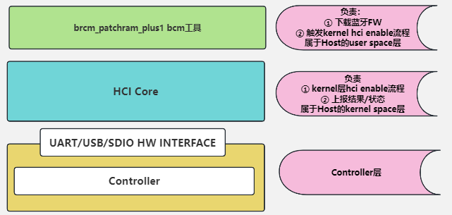
我们在前面已经介绍了蓝牙enable的三种方式,而还有一些芯片厂家自己的工具,不具有通用性,所以单独拎出来介绍,比如bcm的brcm_patchram_plus1工具,这个工具的作用是在user space下载蓝牙fw以及触发标准的kernel中bt进行SIG HCI command的交互,来进行蓝牙使能的动作,也就是我们所说的这种方式:
另外,brcm_patchram_plus1指令也可以通过几种方式来启动:
- 手动启动
- 自动启动
手动启动这个不用多说,就是我们自己来敲命令行,对于调试阶段这个还是非常有必要的,自动启动的方式就比较多了,你可以自己写脚本,也可以用类似rockchip这种使用udev机制来监听rfkill,来启动特定的service来启动.
在介绍这个工具之前,我们先来介绍下udev,因为rockchip的开发板是采用这种方式来启动brcm_patchram_plus1工具的。
一. udev介绍
Linux 中的 udev 是一个设备管理器,用于管理用户空间和内核之间的设备文件系统。它在设备连接、移除或改变状态时动态创建和删除设备节点。udev 是现代 Linux 系统中硬件管理的核心部分,主要负责设备文件(如 /dev/sda)的创建和维护。
1. udev 的工作机制
内核设备事件:
-
- 当一个设备被插入或移除时,内核会生成一个
uevent,其中包含了设备的相关信息,如设备的类型、属性等。 - 这些
uevent会通过netlink套接字被传递到用户空间。
- 当一个设备被插入或移除时,内核会生成一个
udev 监控 uevent:
-
- udev 守护进程(
udevd)监听这些uevent,并根据事件的内容决定如何处理该事件。udev 根据事件的类型和设备的属性,决定是否创建、修改或删除对应的设备节点。
- udev 守护进程(
设备规则匹配:
-
- udev 使用规则文件来决定如何处理设备事件。这些规则文件通常存储在
/etc/udev/rules.d/和/lib/udev/rules.d/目录下。 - 规则文件的语法允许你匹配设备属性(如厂商 ID、产品 ID、序列号等),并基于这些属性执行特定的动作,如创建符号链接、更改设备文件权限或名称、运行脚本等。
- udev 使用规则文件来决定如何处理设备事件。这些规则文件通常存储在
设备节点的创建:
-
- 如果 udev 规则匹配成功,udev 会在
/dev/目录下创建对应的设备节点(如/dev/sda),并且可以创建额外的符号链接或执行额外的操作。
- 如果 udev 规则匹配成功,udev 会在
设备管理的灵活性:
-
- udev 的规则系统非常灵活,你可以定义自定义的规则来适应不同的设备管理需求。例如,可以为特定的 USB 设备创建特定的符号链接,或者当设备插入时自动执行某个脚本。
承接上篇rfkill文章,我们可以看到rfkill的rfkill_set_block后会上报一个uevent
static void rfkill_set_block(struct rfkill *rfkill, bool blocked)
{
	unsigned long flags;
	bool prev, curr;
	int err;

	if (unlikely(rfkill->dev.power.power_state.event & PM_EVENT_SLEEP))
		return;

	/*
	 * Some platforms (...!) generate input events which affect the
	 * _hard_ kill state -- whenever something tries to change the
	 * current software state query the hardware state too.
	 */
	if (rfkill->ops->query)
		rfkill->ops->query(rfkill, rfkill->data);

	spin_lock_irqsave(&rfkill->lock, flags);
	prev = rfkill->state & RFKILL_BLOCK_SW;

	if (rfkill->state & RFKILL_BLOCK_SW)
		rfkill->state |= RFKILL_BLOCK_SW_PREV;
	else
		rfkill->state &= ~RFKILL_BLOCK_SW_PREV;

	if (blocked)
		rfkill->state |= RFKILL_BLOCK_SW;
	else
		rfkill->state &= ~RFKILL_BLOCK_SW;

	rfkill->state |= RFKILL_BLOCK_SW_SETCALL;
	spin_unlock_irqrestore(&rfkill->lock, flags);

    /* 调用特定的rfkill设备驱动中的file operation中的set block */
	err = rfkill->ops->set_block(rfkill->data, blocked);

	spin_lock_irqsave(&rfkill->lock, flags);
	if (err) {
		/*
		 * Failed -- reset status to _prev, this may be different
		 * from what set set _PREV to earlier in this function
		 * if rfkill_set_sw_state was invoked.
		 */
		if (rfkill->state & RFKILL_BLOCK_SW_PREV)
			rfkill->state |= RFKILL_BLOCK_SW;
		else
			rfkill->state &= ~RFKILL_BLOCK_SW;
	}
	rfkill->state &= ~RFKILL_BLOCK_SW_SETCALL;
	rfkill->state &= ~RFKILL_BLOCK_SW_PREV;
	curr = rfkill->state & RFKILL_BLOCK_SW;
	spin_unlock_irqrestore(&rfkill->lock, flags);

	rfkill_led_trigger_event(rfkill);

    /* 注意,这点非常重要,上层可以做很多事情 */
	if (prev != curr)
		rfkill_event(rfkill);
}
static void rfkill_event(struct rfkill *rfkill)
{
if (!rfkill->registered)
return;
kobject_uevent(&rfkill->dev.kobj, KOBJ_CHANGE);
/* also send event to /dev/rfkill */
rfkill_send_events(rfkill, RFKILL_OP_CHANGE);
}从这里发送到user space。而用户空间就是通过systemd-udevd来监听内核上来的uevent

2. udev 规则的结构
一个 udev 规则文件由一系列的规则组成,每条规则通常由以下部分构成:
- 匹配条件:
-
- 匹配条件用于过滤设备属性。例如,
ATTR{idVendor}=="1234"可以匹配 USB 设备的厂商 ID 为1234的设备。
- 匹配条件用于过滤设备属性。例如,
- 动作(Action):
-
- 当匹配条件满足时,执行相应的动作。常见的动作包括
NAME(命名设备文件)、SYMLINK(创建符号链接)、RUN(运行脚本或命令)等。
- 当匹配条件满足时,执行相应的动作。常见的动作包括
下面就是蓝牙的一个rules,在目录/lib/udev/rules.d/50-bluetooth.rules

SUBSYSTEM=="rfkill", ACTION=="change", ATTR{name}=="bt_default", ATTR{type}=="bluetooth", ATTRS{state}=="1", RUN+="/bin/systemctl start bt-attach.service"

SUBSYSTEM=="rfkill", ACTION=="change", ATTR{name}=="bt_default", ATTR{type}=="bluetooth", ATTRS{state}=="0", RUN+="/bin/systemctl stop bt-attach.service"
可以看到这里就是监听了rfkill的状态变化,如果是1,那么/bin/systemctl start bt-attach.service 来启动bt-attach.service,如果是0,那么通过/bin/systemctl stop bt-attach.service 来停止bt-attach.service服务。
3. bt-attach.service服务

其中注意bt-attach并不是我们说的bluez的工具btattach,还是有差异的哈,注意看中间的横线,而这里的bt-attach是一个脚本。
4. bt-attach脚本解析
首先,我们来cat下这个脚本cat /usr/bin/bt-attach
#!/usr/bin/env bash

model_name=$(tr -d '\0' </sys/firmware/devicetree/base/model | tr 'a-z' 'A-Z')

while read line
do
        chip_name=$(echo ${line} | cut -d ' ' -f 1)

        if [[ ${model_name} == *3588* ]]; then
                uart=$(basename /sys/firmware/devicetree/base/pinctrl/wireless-bluetooth/uart*-gpios | tr -cd "[0-9]")
                uart="/dev/ttyS${uart}"
                break
        elif [[ ${model_name} == *${chip_name}* ]]; then
                uart=$(echo ${line} | cut -d ' ' -f 2)
                break
        fi

done < /usr/bin/bt_uart.cfg

bt_type=$(rk_wifi_gettype)

rtk_attach() {
        ret=`ps -ef |grep rtk_hciattach |grep -v "grep" |wc -l`
        if [ ${ret} = 1 ]; then
            killall rtk_hciattach
            sleep 1
        fi
        /usr/bin/rtk_hciattach -n -s 115200 ${uart} rtk_h5 1500000 noflow &
}

if [[ ${bt_type} = "RTL"* ]]; then
        rtk_attach
        exit 0
else
        killall brcm_patchram_plus1
        fwname=$(/usr/bin/bt_fwname ${uart})

        if [[ ${fwname} = "bcm43438a1.hcd" ]]; then
                ln -sf /vendor/etc/firmware/nvram_ap6212a.txt /vendor/etc/firmware/nvram.txt
        elif [[ ${fwname} = "BCM4345C0.hcd" ]]; then
                ln -sf /vendor/etc/firmware/nvram_ap6255.txt /vendor/etc/firmware/nvram.txt
        fi

        start-stop-daemon --start --oknodo --pidfile /var/run/hciattach.pid --background --startas \
/usr/bin/brcm_patchram_plus1 -- --enable_hci --no2bytes --use_baudrate_for_download \
--tosleep  200000 --baudrate 1500000 --patchram /system/etc/firmware/${fwname} ${uart}
fi

exit 0
我们可以看到串口号是如下,rk3399是/dev/ttyS0
root@firefly:~# cat /usr/bin/bt_uart.cfg
1808 /dev/ttyS4
3128 /dev/ttyS0
3288 /dev/ttyS0
3308 /dev/ttyS4
3328 /dev/ttyS2
3399 /dev/ttyS0
3566 /dev/ttyS1
3568 /dev/ttyS8
1126 /dev/ttyS0
PX30 /dev/ttyS1
3588 /dev/ttyS6
其次我们不是realtek的芯片,所以通过这里来启动
start-stop-daemon --start --oknodo --pidfile /var/run/hciattach.pid --background --startas \
/usr/bin/brcm_patchram_plus1 -- --enable_hci --no2bytes --use_baudrate_for_download \
--tosleep  200000 --baudrate 1500000 --patchram /system/etc/firmware/${fwname} ${uart}
这里说白了就是启动brcm_patchram_plus1 这个工具,后面带有一堆参数,包括波特率啦,fw路径啦,串口号啦等,那我们就直接来分析下brcm_patchram_plus1这个工具的源码吧!
二. brcm_patchram_plus1源码介绍
这个文件在路径Z:\board\rk3399\linux\rk3399_linux_release_v2.5.1_20210301\external\rkwifibt\brcm_tools中,其实bcm已经非常成熟,不太推荐用这种私有模式,这个工具跟hciattach的作用非常像,完全可以用hciattach来代替,也可以看他这个TODO也是很醒目,哈哈
![]()
但是本着把这bluez讲的面面俱到的初衷,我还是来介绍下这个工具的source code.
1. main函数
启动过程在main函数中,你可以看到他的流程,我们先大体看下,后面我们来拆分下。
int main (int argc, char **argv)
{
    #ifdef ANDROID
    read_default_bdaddr();
    #endif
    fprintf(stderr, "###AMPAK FW Auto detection patch version = [%s]###\n", FW_TABLE_VERSION);
    if (parse_cmd_line(argc, argv)) {
        exit(1);
    }

    if (uart_fd < 0) {
        exit(2);
    }

    init_uart();

    proc_reset();
    proc_read_local_name();
    proc_open_patchram();

    if (use_baudrate_for_download) {
        if (termios_baudrate) {
            proc_baudrate();
        }
    }

    if (hcdfile_fd > 0) {
        proc_patchram();
    }

    if (termios_baudrate) {
        proc_baudrate();
    }

    if (bdaddr_flag) {
        proc_bdaddr();
    }

    if (enable_lpm) {
        proc_enable_lpm();
    }

    if (scopcm) {
        proc_scopcm();
    }

    if (i2s) {
        proc_i2s();
    }

    if (enable_hci) {
        proc_enable_hci();

        while (1) {
            sleep(UINT_MAX);
        }
    }

    exit(0);
}
在介绍整个流程之前,我们要介绍下hci command发送以及hci event的读取,因为好多发送,接收都大量使用这两个函数,复用性比较强,我们就不一一介绍了。
2. 发送hci command的函数
void
hci_send_cmd(uchar *buf, int len)
{
	if (debug) {
		fprintf(stderr, "writing\n");
		dump(buf, len);
	}

	write(uart_fd, buf, len);
}这个比较简单,就是直接发送数据进uart,可以看到这里的发送并不经过kernel哈
3. 读取hci event的函数
void
read_event(int fd, uchar *buffer)
{
	int i = 0;
	int len = 3;
	int count;

	while ((count = read(fd, &buffer[i], len)) < len) {
		i += count;
		len -= count;
		//fprintf(stderr, "received11 %d\n", count);
	}

	i += count;
	len = buffer[2];
	//fprintf(stderr, "received22 %d\n", count);

	while ((count = read(fd, &buffer[i], len)) < len) {
		i += count;
		len -= count;
	}
	//fprintf(stderr, "received33 %d\n", count);

	if (debug) {
		count += i;

		fprintf(stderr, "received %d\n", count);
		dump(buffer, count);
	}
}就是直接从uart读取数据,可以看到这里的接收同样不经过kernel。
那么他为啥这么实现呢,我们来解析下。
3.1. 读取3个byte
首先先读取3个byte,为什么是3个byte呢?我们看下hci event的格式就有答案了,hci event的格式如下:
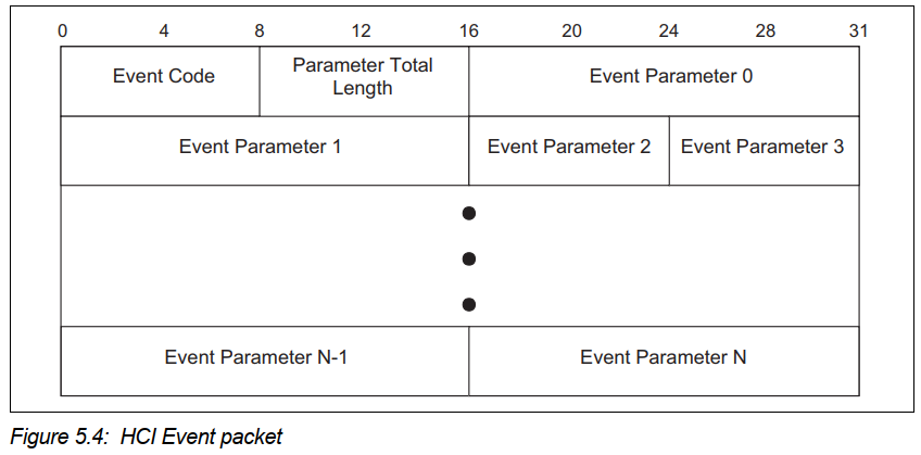
可以看没到event code+parameter len是2个byte,然后加上h4 type的1个byte,所以一共是3个byte
3.2. 根据event len读取长度
这个比较好理解,就是根据长度,把所有的参数读取回来
4. 串口相关的设置
4.1. 打开串口
int
parse_cmd_line(int argc, char **argv)
{
	......

	if (optind < argc) {
		if (debug)
			printf ("%s \n", argv[optind]);
        // 打开串口号,也就是我们上面说明的rk3399的 /dev/ttyS0
		if ((uart_fd = open(argv[optind], O_RDWR | O_NOCTTY)) == -1) {
			fprintf(stderr, "port %s could not be opened, error %d\n",
					argv[2], errno);
		}
	}

	return(0);
}
4.2. 设置串口相关的信息
void
init_uart()
{
	tcflush(uart_fd, TCIOFLUSH);
	tcgetattr(uart_fd, &termios);

#ifndef __CYGWIN__
	cfmakeraw(&termios);
#else
	termios.c_iflag &= ~(IGNBRK | BRKINT | PARMRK | ISTRIP
                | INLCR | IGNCR | ICRNL | IXON);
	termios.c_oflag &= ~OPOST;
	termios.c_lflag &= ~(ECHO | ECHONL | ICANON | ISIG | IEXTEN);
	termios.c_cflag &= ~(CSIZE | PARENB);
	termios.c_cflag |= CS8;
#endif

	termios.c_cflag |= CRTSCTS;
	tcsetattr(uart_fd, TCSANOW, &termios);
	tcflush(uart_fd, TCIOFLUSH);
	tcsetattr(uart_fd, TCSANOW, &termios);
	tcflush(uart_fd, TCIOFLUSH);
	tcflush(uart_fd, TCIOFLUSH);
	cfsetospeed(&termios, B115200);
	cfsetispeed(&termios, B115200);
	tcsetattr(uart_fd, TCSANOW, &termios);
}
以上就是设置了串口相关的信息,包括流控,数据大小,波特率等。
5. 发送hci reset
uchar hci_reset[] = { 0x01, 0x03, 0x0c, 0x00 };
void
expired(int sig)
{
	hci_send_cmd(hci_reset, sizeof(hci_reset));
	alarm(4);
}

void
proc_reset()
{
	signal(SIGALRM, expired);

	fprintf(stderr, "proc_reset");

	hci_send_cmd(hci_reset, sizeof(hci_reset));

	alarm(4);

	read_event(uart_fd, buffer);

	alarm(0);
}
其中hci_reset可以看到{ 0x01, 0x03, 0x0c, 0x00 }; 是标准的h4的格式(1byte h4 type+ hci command),不熟悉的回头去看下hci的章节,然后读取返回的event.
这里加了一个alarm,为了什么呢,就是为了如果发送hci reset不回复的话,触发timeout,4S再发hci reset hci command
6. 发送read local name
uchar hci_read_local_name[] = { 0x01, 0x14, 0x0c, 0x00 };
void
proc_read_local_name()
{
	int i;
	char *p_name;
	hci_send_cmd(hci_read_local_name, sizeof(hci_read_local_name));
	read_event(uart_fd, buffer);
	p_name = &buffer[1+HCI_EVT_CMD_CMPL_LOCAL_NAME_STRING];
	for (i=0; (i < LOCAL_NAME_BUFFER_LEN)||(*(p_name+i) != 0); i++)
		*(p_name+i) = toupper(*(p_name+i));
	strcpy(local_name,p_name);
	fprintf(stderr,"chip id = %s\n", local_name);
}
这里就是读取回来没有下载固件的时候,芯片默认ROM中的名字,保存在local_name,而这个是直接为了下载固件的时候匹配名字
7. open patch ram
这个只要的作用根据文件夹路径以及芯片型号找到特定的hcd文件(.hcd就是bcm的fw)
7.1. 找文件夹路径
int
parse_patchram(char *optarg)
{
	int len = strlen(optarg);
	char *p = optarg+len-1;;
	/*Look for first '/' to know the fw path*/
	while(len>0)
	{
		if(*p == '/')
			break;
		len--;
		p--;
	}
	if(len>0)
	{
		*p =0;
		strcpy(fw_folder_path,optarg);
		fprintf(stderr,"FW folder path = %s\n", fw_folder_path);
	}
#if 0
	char *p;

	if (!(p = strrchr(optarg, '.'))) {
		fprintf(stderr, "file %s not an HCD file\n", optarg);
		exit(3);
	}

	p++;

	if (strcasecmp("hcd", p) != 0) {
		fprintf(stderr, "file %s not an HCD file\n", optarg);
		exit(4);
	}

	if ((hcdfile_fd = open(optarg, O_RDONLY)) == -1) {
		fprintf(stderr, "file %s could not be opened, error %d\n", optarg, errno);
		exit(5);
	}

#endif
	return(0);
}
主要是根据patchram启动参数来决定的

7.2. 整个流程
void
proc_open_patchram()
{
	char fw_path[1024];
	char *p;
	int i;
	fw_auto_detection_entry_t *p_entry;
	p_entry = (fw_auto_detection_entry_t *)fw_auto_detection_table;
	while (p_entry->chip_id != NULL)
	{
		if (strstr(local_name, p_entry->chip_id)!=NULL)
		{
			strcpy(local_name,p_entry->updated_chip_id);
			break;
		}
		p_entry++;
	}
	sprintf(fw_path,"%s/%s.hcd",fw_folder_path,local_name);
	fprintf(stderr, "FW path = %s\n", fw_path);
	if ((hcdfile_fd = open(fw_path, O_RDONLY)) == -1) {
		fprintf(stderr, "file %s could not be opened, error %d\n", fw_path , errno);
		p = local_name;
		fprintf(stderr, "Retry lower case FW name\n");
		for (i=0; (i < LOCAL_NAME_BUFFER_LEN)||(*(p+i) != 0); i++)
			*(p+i) = tolower(*(p+i));
		sprintf(fw_path,"%s/%s.hcd",fw_folder_path,local_name);
		fprintf(stderr, "FW path = %s\n", fw_path);
		if ((hcdfile_fd = open(fw_path, O_RDONLY)) == -1) {
			fprintf(stderr, "file %s could not be opened, error %d\n", fw_path, errno);
			exit(5);
		}
	}
}
可以看到sprintf(fw_path,"%s/%s.hcd",fw_folder_path,local_name); 主要通过组合成特定的fw路径,然后打开hcd,方便后续下载。
8. 设置高波特率方便下载固件更快
8.1. vendor command修改波特率
由于SIG并没有标准的HCI command来修改波特率,所以每家芯片都有自己的vendor command来修改波特率,格式如下:
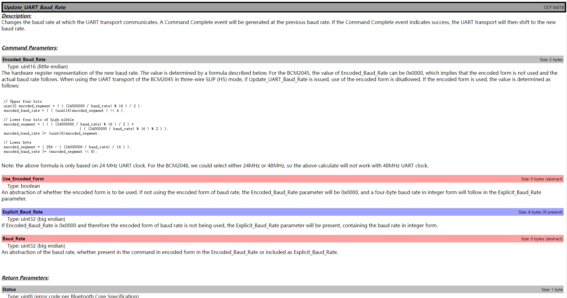
我们可以看到里面的格式为:
uchar hci_update_baud_rate[] = { 0x01, 0x18, 0xfc, 0x06, 0x00, 0x00,
	0x00, 0x00, 0x00, 0x00 };
8.2. 解析/更新波特率
启动参数为:
start-stop-daemon --start --oknodo --pidfile /var/run/hciattach.pid --background --startas \
/usr/bin/brcm_patchram_plus1 -- --enable_hci --no2bytes --use_baudrate_for_download \
--tosleep  200000 --baudrate 1500000 --patchram /system/etc/firmware/${fwname} ${uart}
可以看到是1.5M的波特率。
下面是解析波特率并且更新到我们上面buffer中的vendor command中
int
parse_baudrate(char *optarg)
{
	int baudrate = atoi(optarg);

	if (validate_baudrate(baudrate, &termios_baudrate)) {
		BRCM_encode_baud_rate(baudrate, &hci_update_baud_rate[6]);
	}

	return(0);
}
void
BRCM_encode_baud_rate(uint baud_rate, uchar *encoded_baud)
{
	if(baud_rate == 0 || encoded_baud == NULL) {
		fprintf(stderr, "Baudrate not supported!");
		return;
	}

	encoded_baud[3] = (uchar)(baud_rate >> 24);
	encoded_baud[2] = (uchar)(baud_rate >> 16);
	encoded_baud[1] = (uchar)(baud_rate >> 8);
	encoded_baud[0] = (uchar)(baud_rate & 0xFF);
}
8.3. 平台端更新波特率
if (use_baudrate_for_download) {
		if (termios_baudrate) {
			proc_baudrate();
		}
	}

void
proc_baudrate()
{
	hci_send_cmd(hci_update_baud_rate, sizeof(hci_update_baud_rate));

	read_event(uart_fd, buffer);

	usleep(200000);

	cfsetospeed(&termios, termios_baudrate);
	cfsetispeed(&termios, termios_baudrate);
	tcsetattr(uart_fd, TCSANOW, &termios);

	if (debug) {
		fprintf(stderr, "Done setting baudrate\n");
	}
}
9. 下载fw
整个流程如下:
if (hcdfile_fd > 0) {
    proc_patchram();
}
void
proc_patchram()
{
int len;
hci_send_cmd(hci_download_minidriver, sizeof(hci_download_minidriver));
fprintf(stderr, "send hci_download_minidriver");
read_event(uart_fd, buffer);
if (!no2bytes) {
read(uart_fd, &buffer[0], 2);
}
if (tosleep) {
usleep(tosleep);
}
while (read(hcdfile_fd, &buffer[1], 3)) {
buffer[0] = 0x01;
len = buffer[3];
read(hcdfile_fd, &buffer[4], len);
hci_send_cmd(buffer, len + 4);
read_event(uart_fd, buffer);
}
usleep(200000);
if (use_baudrate_for_download) {
cfsetospeed(&termios, B115200);
cfsetispeed(&termios, B115200);
tcsetattr(uart_fd, TCSANOW, &termios);
}
proc_reset();
}9.1. download minidrver
uchar hci_download_minidriver[] = { 0x01, 0x2e, 0xfc, 0x00 };
hci_send_cmd(hci_download_minidriver, sizeof(hci_download_minidriver));

fprintf(stderr, "send hci_download_minidriver");

read_event(uart_fd, buffer);
这个命令是什么作用呢?这个就相当于告诉芯片"我要下载fw",然后芯片回复"好的,你下载吧"
这个同样的是vendor command

9.2. 从hcd文件中读取,下载到芯片中
while (read(hcdfile_fd, &buffer[1], 3)) {
		buffer[0] = 0x01;

		len = buffer[3];

		read(hcdfile_fd, &buffer[4], len);

		hci_send_cmd(buffer, len + 4);

		read_event(uart_fd, buffer);
	}
在这里注意的是在fw中是标准的hci指令,所以你可以看到处理,是读取3个byte,是放在&buffer[1]位置,在buffer[0]=1, 这个是设置h4 type hci command。
另外,一个隐藏的知识点是,fw的hci指令是什么呢?主要就是两种vendor command


可以看到流程
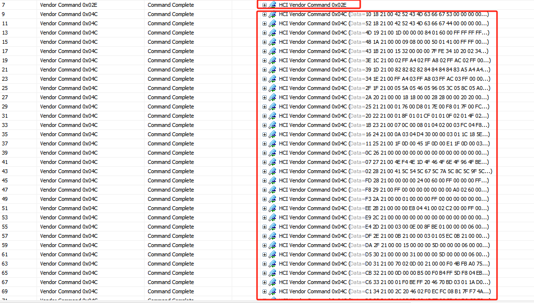

write ram说白了就是把fw写到芯片的ram中,lunch ram,就是类似sw reboot.
9.3. 下载完毕后降低波特率
	if (use_baudrate_for_download) {
		cfsetospeed(&termios, B115200);
		cfsetispeed(&termios, B115200);
		tcsetattr(uart_fd, TCSANOW, &termios);
	}
sw reboot后,芯片恢复到115200了,所以平台的也要对应的设置为115200
然后发送hci reset
9.4. 回复到高波特率
if (termios_baudrate) {
		proc_baudrate();
	}

void
proc_baudrate()
{
	hci_send_cmd(hci_update_baud_rate, sizeof(hci_update_baud_rate));

	read_event(uart_fd, buffer);

	usleep(200000);

	cfsetospeed(&termios, termios_baudrate);
	cfsetispeed(&termios, termios_baudrate);
	tcsetattr(uart_fd, TCSANOW, &termios);

	if (debug) {
		fprintf(stderr, "Done setting baudrate\n");
	}
}
10. 写蓝牙地址
同样,SIG HCI command中并没有写蓝牙地址的操作,也是交于芯片厂家自己实现。所以各个常见也是通过vendor command来实现。
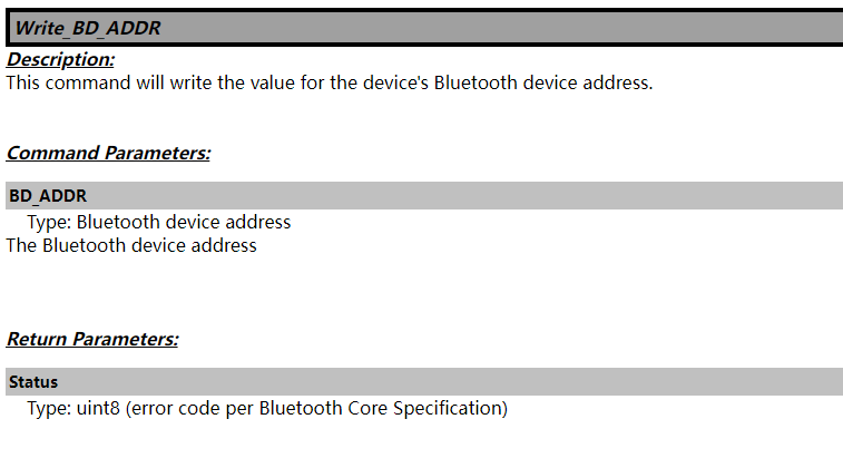
其实这块是option的,有的芯片或者模组在产线已经把蓝牙地址写到芯片中,所以不需要在通过vendor command来写地址
uchar hci_write_bd_addr[] = { 0x01, 0x01, 0xfc, 0x06,
	0x00, 0x00, 0x00, 0x00, 0x00, 0x00 };
void
proc_bdaddr()
{
	hci_send_cmd(hci_write_bd_addr, sizeof(hci_write_bd_addr));

	read_event(uart_fd, buffer);
}
11. 处理低功耗管理
uchar hci_write_sleep_mode[] = { 0x01, 0x27, 0xfc, 0x0c,
	0x01, 0x01, 0x01, 0x01, 0x01, 0x01, 0x01, 0x00, 0x00, 0x00,
	0x00, 0x00 };
if (enable_lpm) {
		proc_enable_lpm();
	}
void
proc_enable_lpm()
{
	hci_send_cmd(hci_write_sleep_mode, sizeof(hci_write_sleep_mode));

	read_event(uart_fd, buffer);
}
同样是vendor command

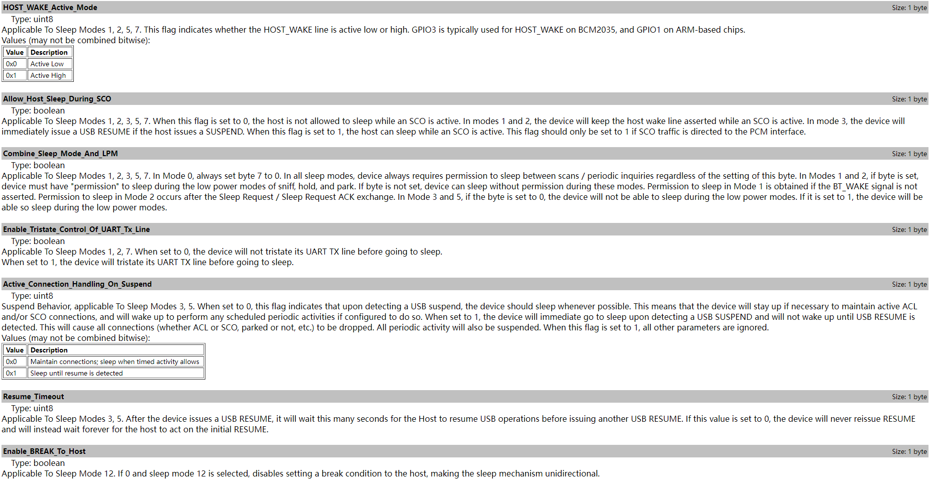
12. 处理音频格式
if (scopcm) {
		proc_scopcm();
	}

	if (i2s) {
		proc_i2s();
	}
12.1. pcm
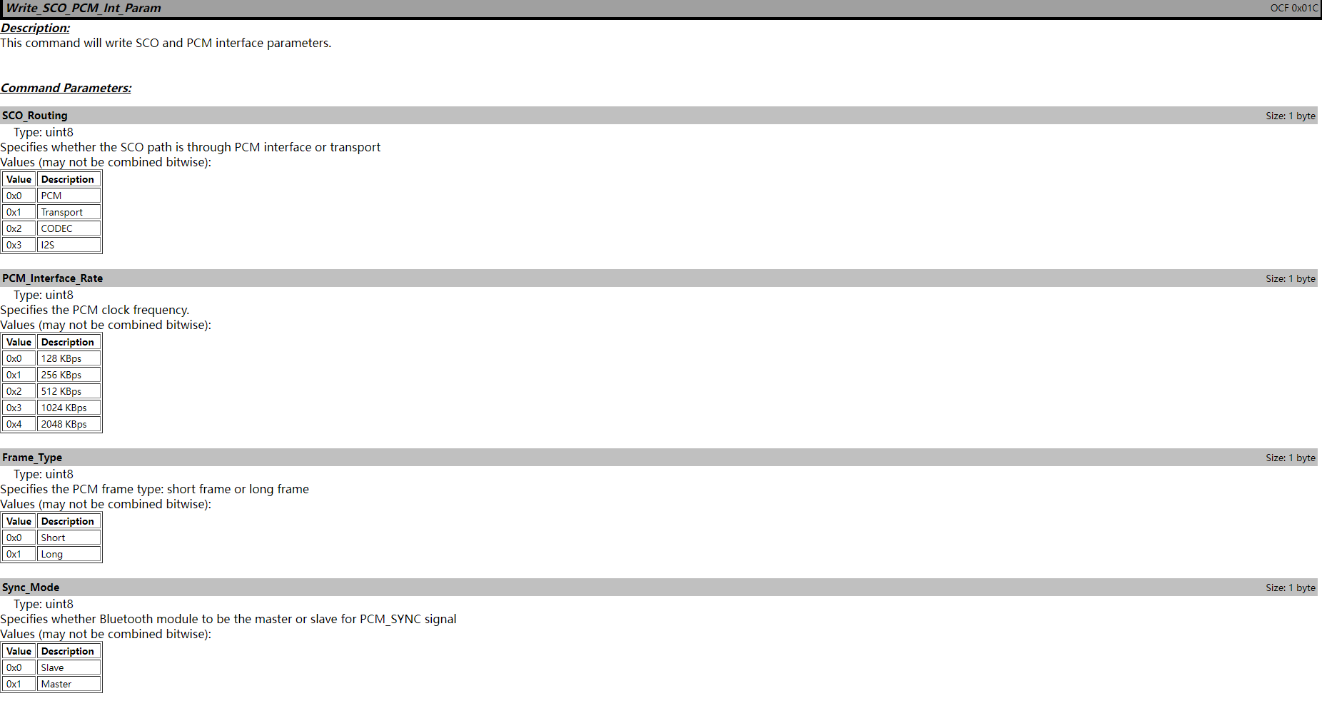
这几个都是vendor command
uchar hci_write_sco_pcm_int[] =
	{ 0x01, 0x1C, 0xFC, 0x05, 0x00, 0x00, 0x00, 0x00, 0x00 };

uchar hci_write_pcm_data_format[] =
	{ 0x01, 0x1e, 0xFC, 0x05, 0x00, 0x00, 0x00, 0x00, 0x00 };
void
proc_scopcm()
{
	hci_send_cmd(hci_write_sco_pcm_int,
		sizeof(hci_write_sco_pcm_int));

	read_event(uart_fd, buffer);

	hci_send_cmd(hci_write_pcm_data_format,
		sizeof(hci_write_pcm_data_format));

	read_event(uart_fd, buffer);
}

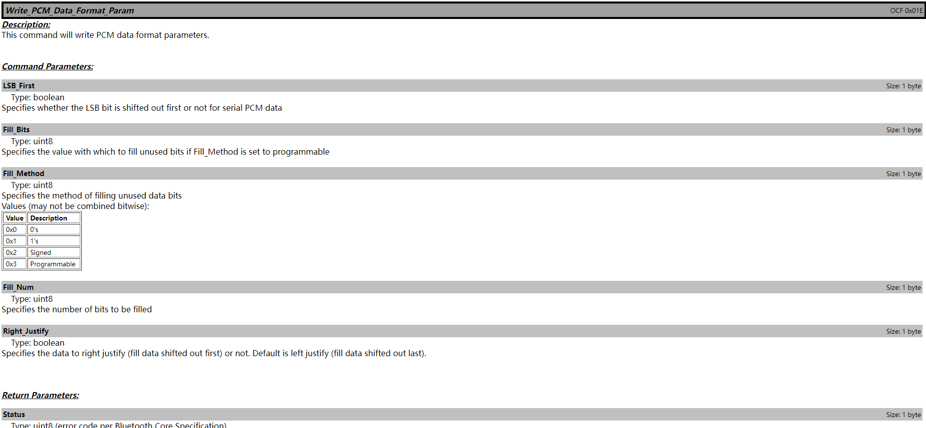
12.2. i2s
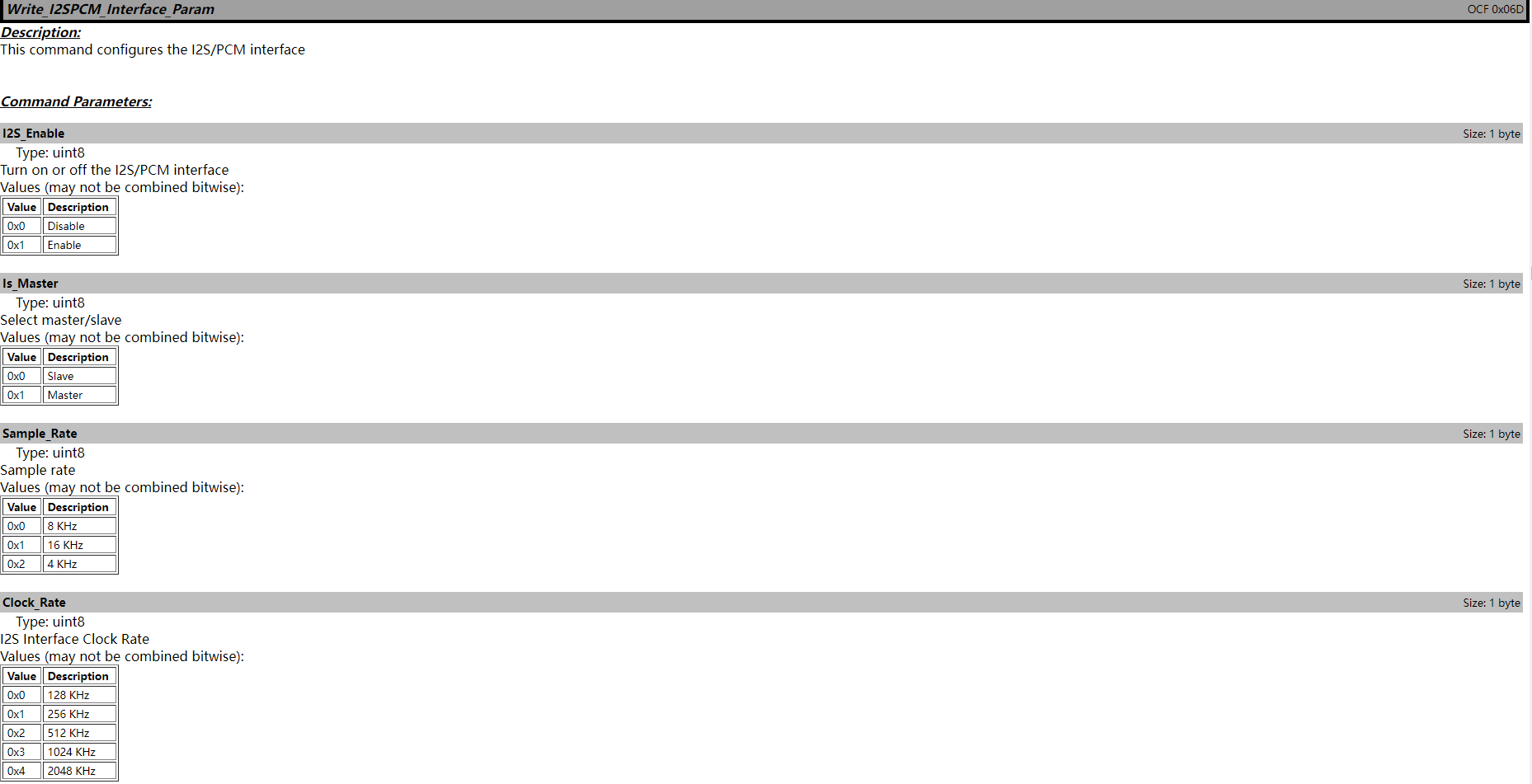
uchar hci_write_i2spcm_interface_param[] =
	{ 0x01, 0x6d, 0xFC, 0x04, 0x00, 0x00, 0x00, 0x00 };
void
proc_i2s()
{
	hci_send_cmd(hci_write_i2spcm_interface_param,
		sizeof(hci_write_i2spcm_interface_param));

	read_event(uart_fd, buffer);
}
13. 触发kernel进行蓝牙enable流程
if (enable_hci) {
		proc_enable_hci();

		while (1) {
			sleep(UINT_MAX);
		}
	}
void
proc_enable_hci()
{
int i = N_HCI;
int proto = HCI_UART_H4;
if (ioctl(uart_fd, TIOCSETD, &i) < 0) {
fprintf(stderr, "Can't set line discipline\n");
return;
}
if (ioctl(uart_fd, HCIUARTSETPROTO, proto) < 0) {
fprintf(stderr, "Can't set hci protocol\n");
return;
}
fprintf(stderr, "Done setting line discpline\n");
return;
}以上就就通过ioctl设置H4 protocol进入kernel,让kernel进行标准的SIG HCI command指令,这个我们在后面介绍,kernel中怎么处理的!
三. kernel介绍
1. 蓝牙子系统目录介绍
内核部分一共分为三个部分,分别为 driver/bluetooth以及net/bluetooth,这里面会引用linux的一些头文件include/net/bluetooth
1.1. driver/bluetooth
这部分的内核代码,你可以参照任意一个kernel版本,包含但是不局限于我们公版使用的内核代码,我就贴下一个开源的查看linux代码的链接吧:
bluetooth - drivers/bluetooth - Linux source code (v6.10.5) - Bootlin
这部分就是整个蓝牙的驱动,包含两个部分:
- 各个厂商的驱动,比如博通的,高通的,瑞昱的,intel,marvell, nxp的等等
- 蓝牙协议栈的transport层,包括uart的h4/h5/bcsp, sdio, usb等
我们来截图下文件,后面我们介绍特定的功能再来介绍下蓝牙的驱动
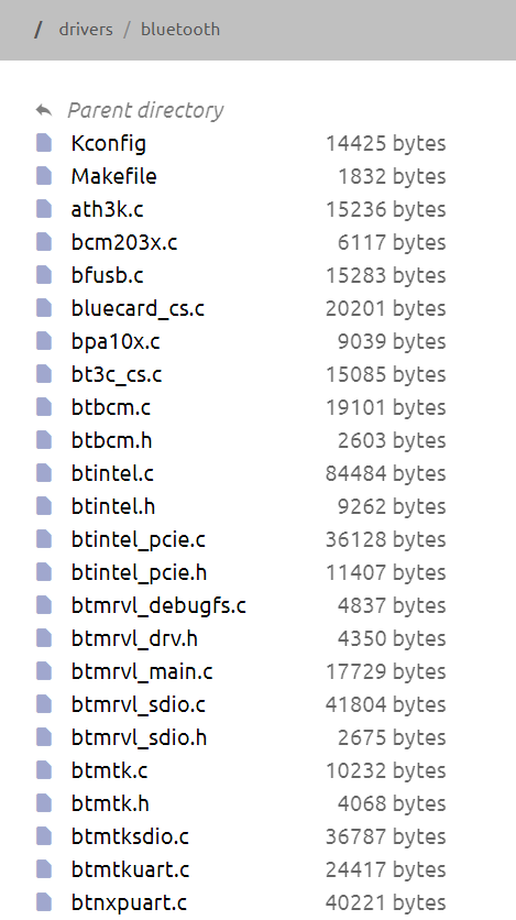
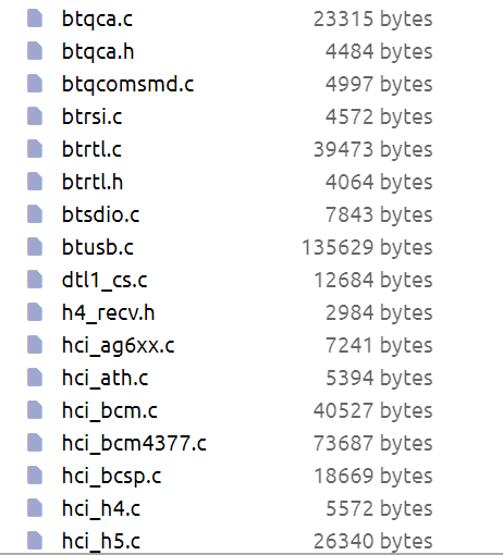
1.2. net/bluetooth
这部分的内核代码,你可以参照任意一个kernel版本,包含但是不局限于我们公版使用的内核代码,我就贴下一个开源的查看linux代码的链接吧:
bluetooth - net/bluetooth - Linux source code (v6.10.5) - Bootlin
部分就是整个蓝牙的protocol,包含bnep/cmtp/hid/rfcomm/l2cap/hci等
我们来截图下文件,后面我们介绍特定的功能再来介绍下蓝牙的内核

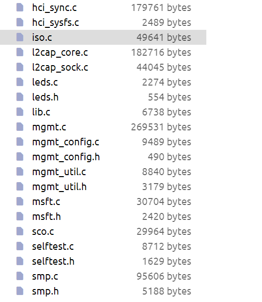
1.3. include\net\bluetooth
这个部分就是net/bluetooth以及driver/bluetooth依赖的头文件部分,链接如下:
bluetooth - include/net/bluetooth - Linux source code (v6.10.5) - Bootlin
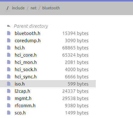
2. kernel中蓝牙子系统启动
在介绍蓝牙子系统启动之前,我们先来看下linux是怎样启动子系统的
2.1. subsys_initcall 介绍
subsys_initcall 是 Linux 内核中的一种宏,用于定义子系统初始化函数。它用于在内核启动过程中初始化特定的子系统。其作用是在内核启动的早期阶段,按照特定的顺序调用初始化函数,以便内核中的不同子系统能够正确配置并准备好使用。
作用
subsys_initcall 的主要作用是注册一个初始化函数,这个函数将在内核启动过程中的特定阶段执行。通常用于那些依赖于核心系统初始化完成,但又希望在大部分设备驱动程序初始化之前运行的子系统。比如,某些文件系统或者网络子系统可能会使用 subsys_initcall 来确保在设备驱动程序之前完成初始化。
启动阶段
Linux 内核的启动过程大致可以分为多个阶段,依次是:
- 架构相关的初始化:包括处理器和内存管理等初始化。
- 核心系统初始化:这部分包括一些基础设施的初始化,比如内存分配器、调度器、中断管理等等。
- 子系统初始化:
subsys_initcall所在的阶段,这时候内核已经具备了运行子系统初始化的基础条件。 - 设备驱动初始化:在子系统初始化之后,设备驱动程序会开始初始化。
- 用户空间的初始化:最后,内核会启动
init进程,进入用户空间。
在这些阶段中,subsys_initcall 所定义的函数会在子系统初始化阶段被调用。内核按照预先定义好的顺序依次调用这些初始化函数,保证内核各个部分按需初始化,从而为设备驱动程序和用户空间的操作提供良好的基础。
2.2. 蓝牙子系统启动
蓝牙子系统首先会先运行 net/bluetooth/af_bluetooth.c中的
subsys_initcall(bt_init);subsys_initcall 这个宏我们已经在前面介绍了,所以会系统运行子系统的时候,会运行蓝牙蓝牙子系统,也就是入口函数bt_init会被执行。
static int __init bt_init(void)
{
	int err;

	sock_skb_cb_check_size(sizeof(struct bt_skb_cb));

	BT_INFO("Core ver %s", VERSION);

	err = bt_selftest();
	if (err < 0)
		return err;

	bt_debugfs = debugfs_create_dir("bluetooth", NULL);

    // 创建/sys/class/bluetooth,这个比较重要
	err = bt_sysfs_init();
	if (err < 0)
		return err;

	err = sock_register(&bt_sock_family_ops);
	if (err < 0) {
		bt_sysfs_cleanup();
		return err;
	}

	BT_INFO("HCI device and connection manager initialized");

	err = hci_sock_init();
	if (err < 0)
		goto error;

	err = l2cap_init();
	if (err < 0)
		goto sock_err;

	err = sco_init();
	if (err < 0) {
		l2cap_exit();
		goto sock_err;
	}

	err = mgmt_init();
	if (err < 0) {
		sco_exit();
		l2cap_exit();
		goto sock_err;
	}

	return 0;

sock_err:
	hci_sock_cleanup();

error:
	sock_unregister(PF_BLUETOOTH);
	bt_sysfs_cleanup();

	return err;
}
这块主要做的东西就是kernel相关的socket init, 也就是以下红框部分
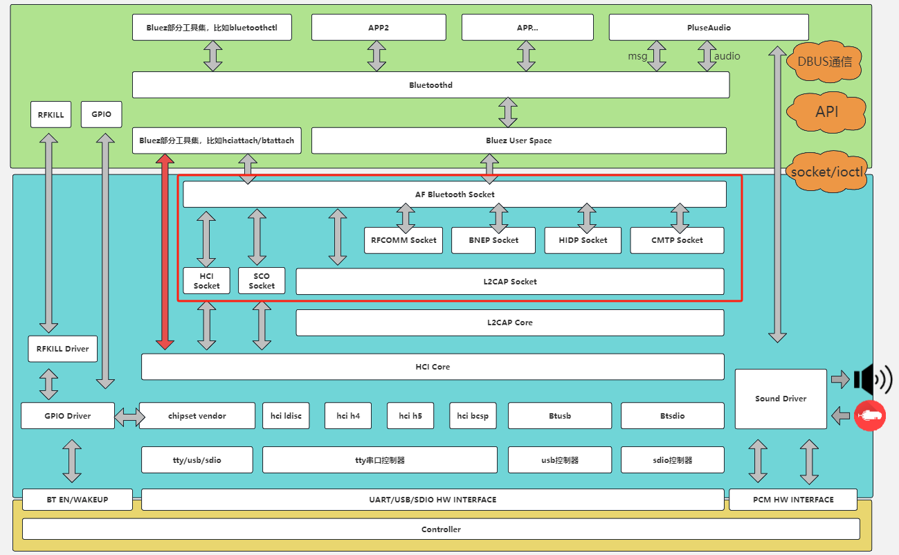

其中RFCOMM/BNEP/HIDP/CMTP的socket初始化并没有默认包含进来,这几个的socket是根据不同的kernel config来决定是否要加载相应的驱动来开启这个功能。路径在
module_init(rfcomm_init);	// net/bluetooth/rfcomm/core.c
module_init(bnep_init);		// net/bluetooth/bnep/core.c
module_init(hidp_init);		// net/bluetooth/hidp/core.c
module_init(cmtp_init);		// net/bluetooth/cmtp/core.c
这里我们就不一一介绍了,等具体介绍到这几个功能的时候,我们再来填坑!
3. HCI UART驱动加载
3.1. module_init 介绍
module_init 是 Linux 内核中的一个宏,用于指定模块加载时的初始化函数。它是设备驱动程序或其他内核模块开发中经常使用的宏。这个宏的主要作用是让内核知道在加载模块时应该调用哪个函数来完成模块的初始化。
我们前面已经介绍了linux的加载过程,我们在列下:
Linux 内核的启动过程大致可以分为多个阶段,依次是:
- 架构相关的初始化:包括处理器和内存管理等初始化。
- 核心系统初始化:这部分包括一些基础设施的初始化,比如内存分配器、调度器、中断管理等等。
- 子系统初始化:
subsys_initcall所在的阶段,这时候内核已经具备了运行子系统初始化的基础条件。 - 设备驱动初始化:在子系统初始化之后,设备驱动程序会开始初始化。
- 用户空间的初始化:最后,内核会启动
init进程,进入用户空间。
而module_init是设备驱动初始化阶段!
3.1.1. 作用
module_init 的作用是将一个函数标记为模块的初始化函数,当模块被加载到内核时,内核会自动调用这个函数。这通常用于设备驱动的初始化工作,比如注册设备、分配资源、设置中断处理程序等。
3.1.2. 使用方法
module_init 宏通常和一个初始化函数一起使用,这个初始化函数需要实现模块加载时的所有必要操作。它的使用方法如下:
static int __init my_module_init(void)
{
    // 模块初始化代码,例如注册设备、分配资源等
    printk(KERN_INFO "My module is loaded.\n");
    return 0; // 返回0表示初始化成功,非0表示失败
}

module_init(my_module_init);在这个示例中,my_module_init 函数是模块的初始化函数,当模块加载时,内核会调用这个函数执行初始化操作。
3.1.3. 工作流程
- 编写初始化函数:首先,开发者编写一个初始化函数,通常带有
__init标记,以指示内核这个函数只在初始化时使用,之后可以被丢弃以节省内存。 - 使用
module_init宏:使用module_init宏将初始化函数与模块加载过程关联起来。 - 模块加载时调用:当用户使用
insmod或modprobe命令加载模块时,内核会自动调用module_init宏指定的初始化函数。有的模块也会默认编译进kernel,自动加载 - 初始化成功或失败:如果初始化函数返回
0,则表示初始化成功,模块加载完成;如果返回非0值,则表示初始化失败,模块加载会被中止。
3.1.4. 模块的卸载
与 module_init 相对的,还有一个 module_exit 宏,它用于指定模块卸载时的清理函数。在卸载模块时,内核会调用该函数进行资源释放和清理工作:
static void __exit my_module_exit(void)
{
    // 模块卸载时的清理代码
    printk(KERN_INFO "My module is unloaded.\n");
}

module_exit(my_module_exit);
3.1.5. 总结
module_init 是用于标记内核模块初始化函数的一个宏。它让内核知道当加载一个模块时,应该调用哪个函数进行初始化操作。结合 module_exit 宏,开发者可以轻松地编写模块的加载和卸载代码。
3.2. hci uart驱动加载
由于我们是介绍的uart蓝牙,蓝牙uart驱动模块的代码在路径 driver/bluetooth/hci_ldisc.c中
module_init(hci_uart_init);所以模块加载的时候(不管是手动加载还是系统自动启动)就会运行hci_uart_init函数
static int __init hci_uart_init(void)
{
    static struct tty_ldisc_ops hci_uart_ldisc;
    int err;

    BT_INFO("HCI UART driver ver %s", VERSION);

    /* Register the tty discipline */
    // 填写tty_ldis operation 函数指针
    memset(&hci_uart_ldisc, 0, sizeof(hci_uart_ldisc));
    hci_uart_ldisc.magic		= TTY_LDISC_MAGIC;
    hci_uart_ldisc.name		= "n_hci";
    hci_uart_ldisc.open		= hci_uart_tty_open;
    hci_uart_ldisc.close		= hci_uart_tty_close;
    hci_uart_ldisc.read		= hci_uart_tty_read;
    hci_uart_ldisc.write		= hci_uart_tty_write;
    hci_uart_ldisc.ioctl		= hci_uart_tty_ioctl;
    hci_uart_ldisc.poll		= hci_uart_tty_poll;
    hci_uart_ldisc.receive_buf	= hci_uart_tty_receive;
    hci_uart_ldisc.write_wakeup	= hci_uart_tty_wakeup;
    hci_uart_ldisc.owner		= THIS_MODULE;

    err = tty_register_ldisc(N_HCI, &hci_uart_ldisc);
    if (err) {
        BT_ERR("HCI line discipline registration failed. (%d)", err);
        return err;
    }

    // 这里就是根据特定的内核开启的来做特定的transport以及芯片来初始化uart protocol
    #ifdef CONFIG_BT_HCIUART_H4
    h4_init();
    #endif
    #ifdef CONFIG_BT_HCIUART_BCSP
    bcsp_init();
    #endif
    #ifdef CONFIG_BT_HCIUART_LL
    ll_init();
    #endif
    #ifdef CONFIG_BT_HCIUART_ATH3K
    ath_init();
    #endif
    #ifdef CONFIG_BT_HCIUART_3WIRE
    h5_init();
    #endif
    #ifdef CONFIG_BT_HCIUART_INTEL
    intel_init();
    #endif
    #ifdef CONFIG_BT_HCIUART_BCM
    bcm_init();
    #endif
    #ifdef CONFIG_BT_HCIUART_QCA
    qca_init();
    #endif

    return 0;
}
初始化特定的transport的地方,是一个结构体指针数组,代码如下:
static const struct hci_uart_proto *hup[HCI_UART_MAX_PROTO];
不同的transport以及特定芯片的驱动,根据以下索引存储到不同的位置:
/* UART protocols */
#define HCI_UART_MAX_PROTO	9

#define HCI_UART_H4	0
#define HCI_UART_BCSP	1
#define HCI_UART_3WIRE	2
#define HCI_UART_H4DS	3
#define HCI_UART_LL	4
#define HCI_UART_ATH3K	5
#define HCI_UART_INTEL	6
#define HCI_UART_BCM	7
#define HCI_UART_QCA	8
4. 用户层触发的kernel行为
plus1的最后的行为是用ioctl触发kernel行为,代码如下:
void
proc_enable_hci()
{
	int i = N_HCI;
	int proto = HCI_UART_H4;
    // 调用内核的tty_ioctl,采用ldisc机制改变hci行规
	if (ioctl(uart_fd, TIOCSETD, &i) < 0) {
		fprintf(stderr, "Can't set line discipline\n");
		return;
	}

	if (ioctl(uart_fd, HCIUARTSETPROTO, proto) < 0) {
		fprintf(stderr, "Can't set hci protocol\n");
		return;
	}
	fprintf(stderr, "Done setting line discpline\n");
	return;
}
而HCIUARTSETPROTO 是我们的重头戏,因为brcm_patchram_plus1是HCI_UART_H4
4.1. HCIUARTSETPROTO ioctl kernel的处理
static int hci_uart_tty_ioctl(struct tty_struct *tty, struct file *file,
			      unsigned int cmd, unsigned long arg)
{
	struct hci_uart *hu = tty->disc_data;
	int err = 0;

	BT_DBG("");

	/* Verify the status of the device */
	if (!hu)
		return -EBADF;

	switch (cmd) {
	case HCIUARTSETPROTO:
		if (!test_and_set_bit(HCI_UART_PROTO_SET, &hu->flags)) {
			err = hci_uart_set_proto(hu, arg);
			if (err) {
				clear_bit(HCI_UART_PROTO_SET, &hu->flags);
				return err;
			}
		} else
			return -EBUSY;
		break;

	.....

	return err;
}
static int hci_uart_set_proto(struct hci_uart *hu, int id)
{
const struct hci_uart_proto *p;
int err;
p = hci_uart_get_proto(id);
if (!p)
return -EPROTONOSUPPORT;
err = p->open(hu);
if (err)
return err;
hu->proto = p;
err = hci_uart_register_dev(hu);
if (err) {
p->close(hu);
return err;
}
set_bit(HCI_UART_PROTO_READY, &hu->flags);
return 0;
}其中hci_uart_get_proto就是获取h4的结构体指针,所以对应的kernel中也是h4相应的处理生效

剩下的我们就不一个函数介绍了,我们贴一个图
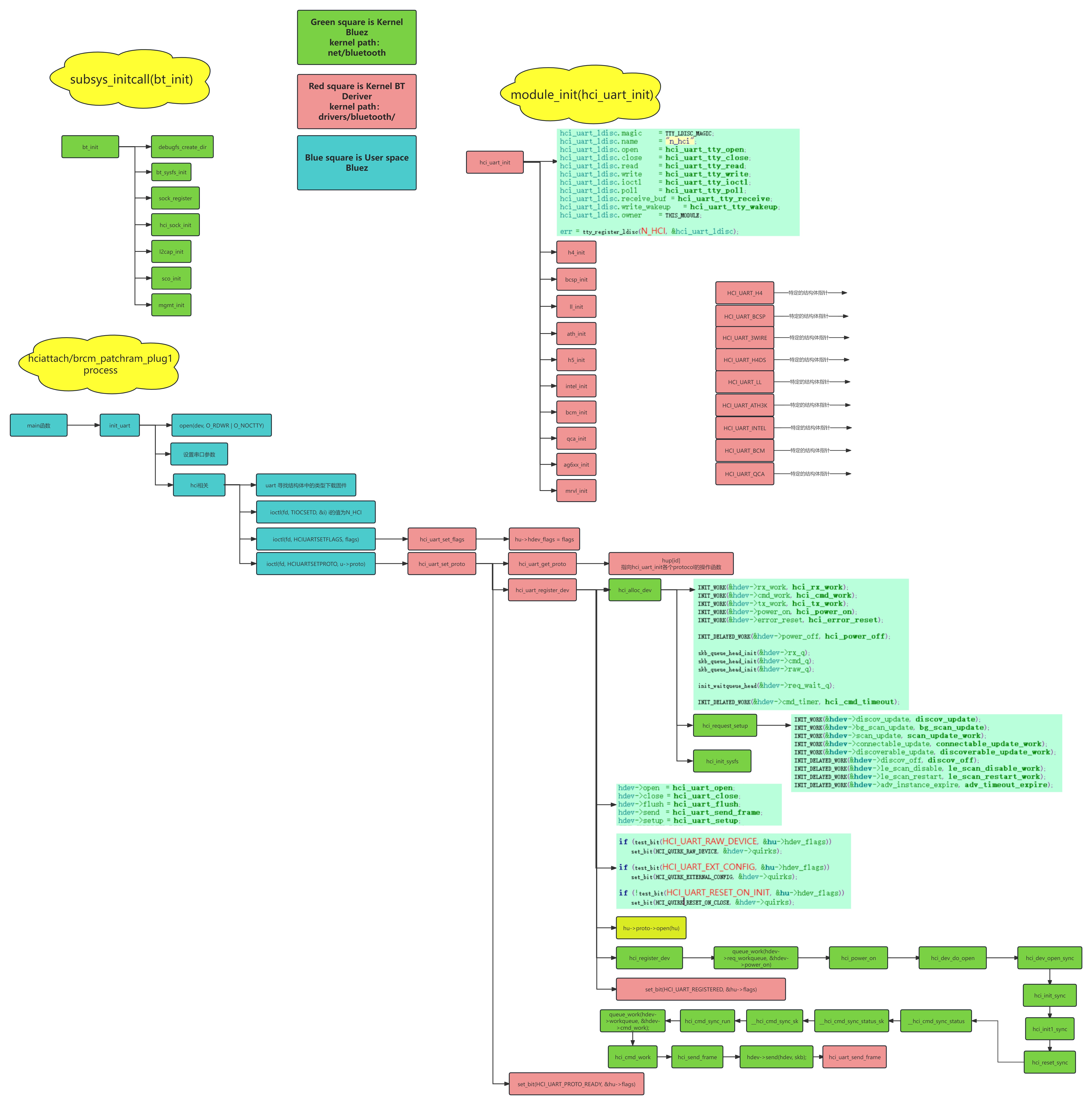
注意:不同的kernel版本之间的函数名称稍微有点差异,这点需要注意
4.2. 蓝牙SIG的初始化流程(下发命令)
4.2.1. hci command发送原理
4.2.1.1. hci_uart_write_work初始化
INIT_WORK(&hu->write_work, hci_uart_write_work);INIT_WORK(&hdev->cmd_work, hci_cmd_work);以上是创建一个两个work queue,一个是hci_uart_write_work,一个是hci_cmd_work
4.2.1.2. hci发送hci command
可以看到在kernel蓝牙子系统中,有很多hci command通过hci_req_add这个函数发送
hci_req_add(req, HCI_OP_READ_BD_ADDR, 0, NULL);

void hci_req_add(struct hci_request *req, u16 opcode, u32 plen,
		 const void *param)
{
	hci_req_add_ev(req, opcode, plen, param, 0);
}
其中hci_req_add_ev实现如下:
void hci_req_add_ev(struct hci_request *req, u16 opcode, u32 plen,
		    const void *param, u8 event)
{
	.....

	skb_queue_tail(&req->cmd_q, skb);
}
因为我们前面有个cmd_q的队列,所以对应的处理如下:
static void hci_cmd_work(struct work_struct *work)
{
    skb = skb_dequeue(&hdev->cmd_q);
    ...
    if (hdev->sent_cmd) {
        atomic_dec(&hdev->cmd_cnt);
        hci_send_frame(hdev, skb);
    }
}
static void hci_send_frame(struct hci_dev *hdev, struct sk_buff *skb)
{
    ...
	err = hdev->send(hdev, skb);
    ...
}
而在前面结构体的send指针是如下:
hdev->open  = hci_uart_open;
hdev->close = hci_uart_close;
hdev->flush = hci_uart_flush;
hdev->send  = hci_uart_send_frame;
hdev->setup = hci_uart_setup;
/* Send frames from HCI layer */
static int hci_uart_send_frame(struct hci_dev *hdev, struct sk_buff *skb)
{
...
hu->proto->enqueue(hu, skb);
hci_uart_tx_wakeup(hu);
return 0;
}其中hu->proto->enqueu就是我们h4 transport的enq的函数指针,也就是这个结构体中的内容:
static const struct hci_uart_proto h4p = {
	.id		= HCI_UART_H4,
	.name		= "H4",
	.open		= h4_open,
	.close		= h4_close,
	.recv		= h4_recv,
	.enqueue	= h4_enqueue,
	.dequeue	= h4_dequeue,
	.flush		= h4_flush,
};
static int h4_enqueue(struct hci_uart *hu, struct sk_buff *skb)
{
struct h4_struct *h4 = hu->priv;
BT_DBG("hu %p skb %p", hu, skb);
/* Prepend skb with frame type */
memcpy(skb_push(skb, 1), &bt_cb(skb)->pkt_type, 1);
skb_queue_tail(&h4->txq, skb);
return 0;
}然后进入了hci_uart_write_work就出发了前面的消息队列
int hci_uart_tx_wakeup(struct hci_uart *hu)
{
	if (test_and_set_bit(HCI_UART_SENDING, &hu->tx_state)) {
		set_bit(HCI_UART_TX_WAKEUP, &hu->tx_state);
		return 0;
	}

	BT_DBG("");

	schedule_work(&hu->write_work);

	return 0;
}
static void hci_uart_write_work(struct work_struct *work)
{
...
while ((skb = hci_uart_dequeue(hu))) {
int len;
set_bit(TTY_DO_WRITE_WAKEUP, &tty->flags);
len = tty->ops->write(tty, skb->data, skb->len);
hdev->stat.byte_tx += len;
skb_pull(skb, len);
if (skb->len) {
hu->tx_skb = skb;
break;
}
hci_uart_tx_complete(hu, bt_cb(skb)->pkt_type);
kfree_skb(skb);
}
...
}这里的tty->ops->write通常由 TTY 子系统在打开终端设备时调用。这个函数的调用过程和 tty 的来源可以追溯到用户空间应用程序通过调用 open() 系统调用来打开一个与终端设备(如 /dev/ttyS0)关联的文件。这个请求最终会进入内核,并由 TTY 子系统处理。
4.2.2. 接收处理
4.2.2.1. rx work queue初始化
INIT_WORK(&hdev->rx_work, hci_rx_work);4.2.2.2. 接收逻辑
/* hci_uart_tty_receive()
 *
 *     Called by tty low level driver when receive data is
 *     available.
 *
 * Arguments:  tty          pointer to tty isntance data
 *             data         pointer to received data
 *             flags        pointer to flags for data
 *             count        count of received data in bytes
 *
 * Return Value:    None
 */
static void hci_uart_tty_receive(struct tty_struct *tty, const u8 *data,
				 char *flags, int count)
{
    ...
	/* It does not need a lock here as it is already protected by a mutex in
	 * tty caller
	 */
	hu->proto->recv(hu, data, count);
    ...

}
我们可以看到注释,这个是底层的tty系统有数据call上来的,所以你在蓝牙子系统中追不到了,如果想继续了解更多,那么就需要了解tty子系统,当然你可以认为底层uart数据从这个函数入口开始的!
h4的recv的函数指针如下:
static const struct hci_uart_proto h4p = {
	.id		= HCI_UART_H4,
	.name		= "H4",
	.open		= h4_open,
	.close		= h4_close,
	.recv		= h4_recv,
	.enqueue	= h4_enqueue,
	.dequeue	= h4_dequeue,
	.flush		= h4_flush,
};
static const struct h4_recv_pkt h4_recv_pkts[] = {
{ H4_RECV_ACL, .recv = hci_recv_frame },
{ H4_RECV_SCO, .recv = hci_recv_frame },
{ H4_RECV_EVENT, .recv = hci_recv_frame },
};
/* Recv data */
static int h4_recv(struct hci_uart *hu, const void *data, int count)
{
...
h4->rx_skb = h4_recv_buf(hu->hdev, h4->rx_skb, data, count,
h4_recv_pkts, ARRAY_SIZE(h4_recv_pkts));
...
return count;
}/* Receive frame from HCI drivers */
int hci_recv_frame(struct hci_dev *hdev, struct sk_buff *skb)
{
...
skb_queue_tail(&hdev->rx_q, skb);
queue_work(hdev->workqueue, &hdev->rx_work);
return 0;
}然后开始进入队列处理函数hci_rx_work处理
然后再分不同阶段去处理acl,sco,event处理了
static void hci_rx_work(struct work_struct *work)
{
	...

	while ((skb = skb_dequeue(&hdev->rx_q))) {
		...

		/* Process frame */
		switch (bt_cb(skb)->pkt_type) {
		case HCI_EVENT_PKT:
			BT_DBG("%s Event packet", hdev->name);
			hci_event_packet(hdev, skb);
			break;

		case HCI_ACLDATA_PKT:
			BT_DBG("%s ACL data packet", hdev->name);
			hci_acldata_packet(hdev, skb);
			break;

		case HCI_SCODATA_PKT:
			BT_DBG("%s SCO data packet", hdev->name);
			hci_scodata_packet(hdev, skb);
			break;

		default:
			kfree_skb(skb);
			break;
		}
	}
}
4.2.3. 第零阶段(HCI_UNCONFIGURED)
static void hci_init0_req(struct hci_request *req, unsigned long opt)
{
	struct hci_dev *hdev = req->hdev;

	BT_DBG("%s %ld", hdev->name, opt);

	/* Reset */
	if (!test_bit(HCI_QUIRK_RESET_ON_CLOSE, &hdev->quirks))
		hci_reset_req(req, 0);

	/* Read Local Version */
	hci_req_add(req, HCI_OP_READ_LOCAL_VERSION, 0, NULL);

	/* Read BD Address */
	if (hdev->set_bdaddr)
		hci_req_add(req, HCI_OP_READ_BD_ADDR, 0, NULL);
}
可以看到有hci reset, read local verson, read local name的操作
4.2.4. 第一阶段
static void hci_init1_req(struct hci_request *req, unsigned long opt)
{
	struct hci_dev *hdev = req->hdev;

	BT_DBG("%s %ld", hdev->name, opt);

	/* Reset */
	if (!test_bit(HCI_QUIRK_RESET_ON_CLOSE, &hdev->quirks))
		hci_reset_req(req, 0);

	switch (hdev->dev_type) {
	case HCI_BREDR:
		bredr_init(req);
		break;

	case HCI_AMP:
		amp_init1(req);
		break;

	default:
		BT_ERR("Unknown device type %d", hdev->dev_type);
		break;
	}
}
static void bredr_init(struct hci_request *req)
{
req->hdev->flow_ctl_mode = HCI_FLOW_CTL_MODE_PACKET_BASED;
/* Read Local Supported Features */
hci_req_add(req, HCI_OP_READ_LOCAL_FEATURES, 0, NULL);
/* Read Local Version */
hci_req_add(req, HCI_OP_READ_LOCAL_VERSION, 0, NULL);
/* Read BD Address */
hci_req_add(req, HCI_OP_READ_BD_ADDR, 0, NULL);
}可以看到有read local feature/ read local version/ read local addr
4.2.5. 第二阶段
static void hci_init2_req(struct hci_request *req, unsigned long opt)
{
	struct hci_dev *hdev = req->hdev;

	if (hdev->dev_type == HCI_AMP)
		return amp_init2(req);

	if (lmp_bredr_capable(hdev))
		bredr_setup(req);
	else
		hci_dev_clear_flag(hdev, HCI_BREDR_ENABLED);

	if (lmp_le_capable(hdev))
		le_setup(req);

	/* All Bluetooth 1.2 and later controllers should support the
	 * HCI command for reading the local supported commands.
	 *
	 * Unfortunately some controllers indicate Bluetooth 1.2 support,
	 * but do not have support for this command. If that is the case,
	 * the driver can quirk the behavior and skip reading the local
	 * supported commands.
	 */
	if (hdev->hci_ver > BLUETOOTH_VER_1_1 &&
	    !test_bit(HCI_QUIRK_BROKEN_LOCAL_COMMANDS, &hdev->quirks))
		hci_req_add(req, HCI_OP_READ_LOCAL_COMMANDS, 0, NULL);

	if (lmp_ssp_capable(hdev)) {
		/* When SSP is available, then the host features page
		 * should also be available as well. However some
		 * controllers list the max_page as 0 as long as SSP
		 * has not been enabled. To achieve proper debugging
		 * output, force the minimum max_page to 1 at least.
		 */
		hdev->max_page = 0x01;

		if (hci_dev_test_flag(hdev, HCI_SSP_ENABLED)) {
			u8 mode = 0x01;

			hci_req_add(req, HCI_OP_WRITE_SSP_MODE,
				    sizeof(mode), &mode);
		} else {
			struct hci_cp_write_eir cp;

			memset(hdev->eir, 0, sizeof(hdev->eir));
			memset(&cp, 0, sizeof(cp));

			hci_req_add(req, HCI_OP_WRITE_EIR, sizeof(cp), &cp);
		}
	}

	if (lmp_inq_rssi_capable(hdev) ||
	    test_bit(HCI_QUIRK_FIXUP_INQUIRY_MODE, &hdev->quirks)) {
		u8 mode;

		/* If Extended Inquiry Result events are supported, then
		 * they are clearly preferred over Inquiry Result with RSSI
		 * events.
		 */
		mode = lmp_ext_inq_capable(hdev) ? 0x02 : 0x01;

		hci_req_add(req, HCI_OP_WRITE_INQUIRY_MODE, 1, &mode);
	}

	if (lmp_inq_tx_pwr_capable(hdev))
		hci_req_add(req, HCI_OP_READ_INQ_RSP_TX_POWER, 0, NULL);

	if (lmp_ext_feat_capable(hdev)) {
		struct hci_cp_read_local_ext_features cp;

		cp.page = 0x01;
		hci_req_add(req, HCI_OP_READ_LOCAL_EXT_FEATURES,
			    sizeof(cp), &cp);
	}

	if (hci_dev_test_flag(hdev, HCI_LINK_SECURITY)) {
		u8 enable = 1;
		hci_req_add(req, HCI_OP_WRITE_AUTH_ENABLE, sizeof(enable),
			    &enable);
	}
}
4.2.6. 第三阶段
static void hci_init3_req(struct hci_request *req, unsigned long opt)
{
	struct hci_dev *hdev = req->hdev;
	u8 p;

	hci_setup_event_mask(req);

	if (hdev->commands[6] & 0x20 &&
	    !test_bit(HCI_QUIRK_BROKEN_STORED_LINK_KEY, &hdev->quirks)) {
		struct hci_cp_read_stored_link_key cp;

		bacpy(&cp.bdaddr, BDADDR_ANY);
		cp.read_all = 0x01;
		hci_req_add(req, HCI_OP_READ_STORED_LINK_KEY, sizeof(cp), &cp);
	}

	if (hdev->commands[5] & 0x10)
		hci_setup_link_policy(req);

	if (hdev->commands[8] & 0x01)
		hci_req_add(req, HCI_OP_READ_PAGE_SCAN_ACTIVITY, 0, NULL);

	/* Some older Broadcom based Bluetooth 1.2 controllers do not
	 * support the Read Page Scan Type command. Check support for
	 * this command in the bit mask of supported commands.
	 */
	if (hdev->commands[13] & 0x01)
		hci_req_add(req, HCI_OP_READ_PAGE_SCAN_TYPE, 0, NULL);

	if (lmp_le_capable(hdev)) {
		u8 events[8];

		memset(events, 0, sizeof(events));
		events[0] = 0x0f;

		if (hdev->le_features[0] & HCI_LE_ENCRYPTION)
			events[0] |= 0x10;	/* LE Long Term Key Request */

		/* If controller supports the Connection Parameters Request
		 * Link Layer Procedure, enable the corresponding event.
		 */
		if (hdev->le_features[0] & HCI_LE_CONN_PARAM_REQ_PROC)
			events[0] |= 0x20;	/* LE Remote Connection
						 * Parameter Request
						 */

		/* If the controller supports the Data Length Extension
		 * feature, enable the corresponding event.
		 */
		if (hdev->le_features[0] & HCI_LE_DATA_LEN_EXT)
			events[0] |= 0x40;	/* LE Data Length Change */

		/* If the controller supports Extended Scanner Filter
		 * Policies, enable the correspondig event.
		 */
		if (hdev->le_features[0] & HCI_LE_EXT_SCAN_POLICY)
			events[1] |= 0x04;	/* LE Direct Advertising
						 * Report
						 */

		/* If the controller supports the LE Read Local P-256
		 * Public Key command, enable the corresponding event.
		 */
		if (hdev->commands[34] & 0x02)
			events[0] |= 0x80;	/* LE Read Local P-256
						 * Public Key Complete
						 */

		/* If the controller supports the LE Generate DHKey
		 * command, enable the corresponding event.
		 */
		if (hdev->commands[34] & 0x04)
			events[1] |= 0x01;	/* LE Generate DHKey Complete */

		hci_req_add(req, HCI_OP_LE_SET_EVENT_MASK, sizeof(events),
			    events);

		if (hdev->commands[25] & 0x40) {
			/* Read LE Advertising Channel TX Power */
			hci_req_add(req, HCI_OP_LE_READ_ADV_TX_POWER, 0, NULL);
		}

		if (hdev->commands[26] & 0x40) {
			/* Read LE White List Size */
			hci_req_add(req, HCI_OP_LE_READ_WHITE_LIST_SIZE,
				    0, NULL);
		}

		if (hdev->commands[26] & 0x80) {
			/* Clear LE White List */
			hci_req_add(req, HCI_OP_LE_CLEAR_WHITE_LIST, 0, NULL);
		}

		if (hdev->le_features[0] & HCI_LE_DATA_LEN_EXT) {
			/* Read LE Maximum Data Length */
			hci_req_add(req, HCI_OP_LE_READ_MAX_DATA_LEN, 0, NULL);

			/* Read LE Suggested Default Data Length */
			hci_req_add(req, HCI_OP_LE_READ_DEF_DATA_LEN, 0, NULL);
		}

		hci_set_le_support(req);
	}

	/* Read features beyond page 1 if available */
	for (p = 2; p < HCI_MAX_PAGES && p <= hdev->max_page; p++) {
		struct hci_cp_read_local_ext_features cp;

		cp.page = p;
		hci_req_add(req, HCI_OP_READ_LOCAL_EXT_FEATURES,
			    sizeof(cp), &cp);
	}
}
4.2.7. 第四阶段
static void hci_init4_req(struct hci_request *req, unsigned long opt)
{
	struct hci_dev *hdev = req->hdev;

	/* Some Broadcom based Bluetooth controllers do not support the
	 * Delete Stored Link Key command. They are clearly indicating its
	 * absence in the bit mask of supported commands.
	 *
	 * Check the supported commands and only if the the command is marked
	 * as supported send it. If not supported assume that the controller
	 * does not have actual support for stored link keys which makes this
	 * command redundant anyway.
	 *
	 * Some controllers indicate that they support handling deleting
	 * stored link keys, but they don't. The quirk lets a driver
	 * just disable this command.
	 */
	if (hdev->commands[6] & 0x80 &&
	    !test_bit(HCI_QUIRK_BROKEN_STORED_LINK_KEY, &hdev->quirks)) {
		struct hci_cp_delete_stored_link_key cp;

		bacpy(&cp.bdaddr, BDADDR_ANY);
		cp.delete_all = 0x01;
		hci_req_add(req, HCI_OP_DELETE_STORED_LINK_KEY,
			    sizeof(cp), &cp);
	}

	/* Set event mask page 2 if the HCI command for it is supported */
	if (hdev->commands[22] & 0x04)
		hci_set_event_mask_page_2(req);

	/* Read local codec list if the HCI command is supported */
	if (hdev->commands[29] & 0x20)
		hci_req_add(req, HCI_OP_READ_LOCAL_CODECS, 0, NULL);

	/* Get MWS transport configuration if the HCI command is supported */
	if (hdev->commands[30] & 0x08)
		hci_req_add(req, HCI_OP_GET_MWS_TRANSPORT_CONFIG, 0, NULL);

	/* Check for Synchronization Train support */
	if (lmp_sync_train_capable(hdev))
		hci_req_add(req, HCI_OP_READ_SYNC_TRAIN_PARAMS, 0, NULL);

	/* Enable Secure Connections if supported and configured */
	if (hci_dev_test_flag(hdev, HCI_SSP_ENABLED) &&
	    bredr_sc_enabled(hdev)) {
		u8 support = 0x01;

		hci_req_add(req, HCI_OP_WRITE_SC_SUPPORT,
			    sizeof(support), &support);
	}
}


