蜂鸣器(2):12V有源蜂鸣器
在本教程中,我们将学习如何对Arduino进行编程,以控制12V有源蜂鸣器以产生响亮的声音。如果您想控制 5V 有源/无源蜂鸣器,请查看此 Arduino 压电蜂鸣器教程
Hardware Required 所需硬件
| 1 | × | Arduino UNO or Genuino UNO | |
|---|---|---|---|
| 1 | × | USB 2.0 cable type A/B | |
| 1 | × | Relay 中继 | |
| 1 | × | 12V Active Buzzer | |
| 1 | × | 12V Power Adapter | |
| 1 | × | DC Power Jack 直流电源插孔 | |
| 1 | × | Jumper Wires 跳线 | |
| 1 | × | (Optional) 9V Power Adapter for Arduino | |
| 1 | × | (Recommended) Screw Terminal Block Shield for Arduino Uno | |
| 1 | × | (Optional) Transparent Acrylic Enclosure For Arduino Uno |
About 12V Active Buzzer 关于12V有源蜂鸣器
The 12V Active Buzzer can produce a loud sound, which is suitable for the alarming system.
12V有源蜂鸣器可以产生响亮的声音,适用于报警系统。
Pinout 引脚排列

12V Active Buzzer usually has two pins:
12V 有源蜂鸣器通常有两个引脚:
- Negative (-) pin (black): needs to be connected to GND of DC power supply
负极(-)引脚(黑色):需要连接到直流电源的GND - Positive (+) pin (red): needs to be connected to 12V of DC power supply
正极(+)引脚(红色):需要连接12V直流电源
How to Control 12V Active Buzzer 如何控制 12V 有源蜂鸣器
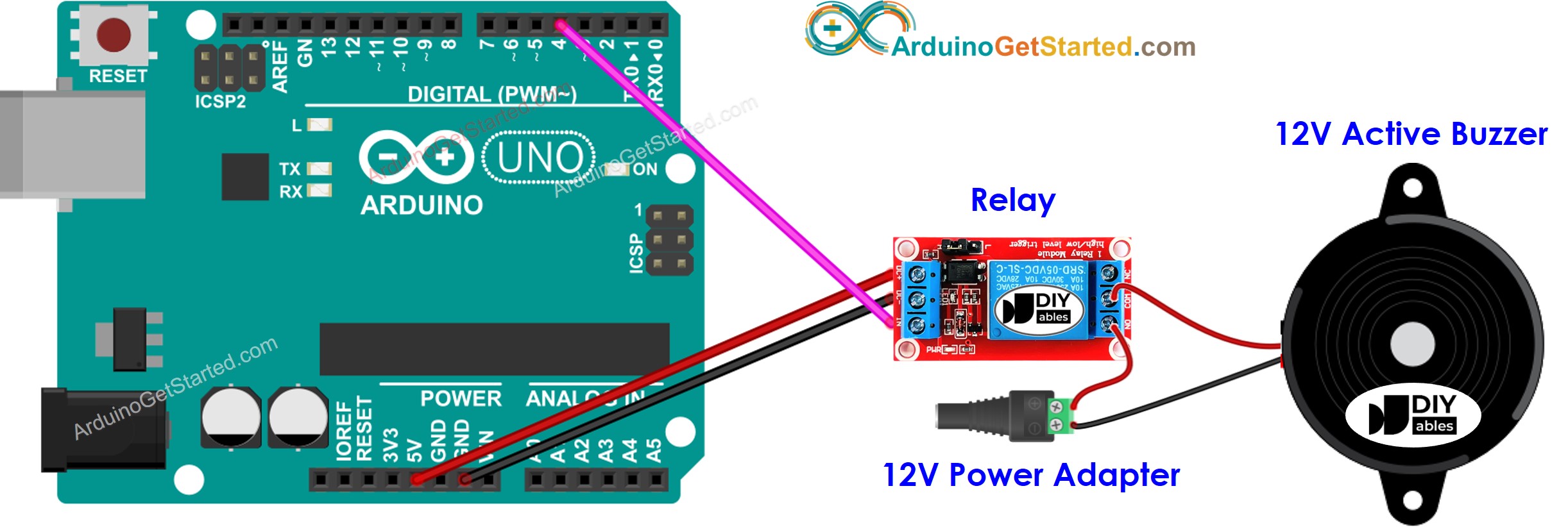
If 12V active buzzer is powered by 12V power supply, it make sound. To control a 12V active buzzer, we need to use a relay in between Arduino and 12V active buzzer. Arduino can control the 12V active buzzer via the relay. If you do not know about relay (pinout, how it works, how to program …), learn about relay in the Arduino - Relay tutorial
如果 12V 有源蜂鸣器由 12V 电源供电,它会发出声音。要控制 12V 有源蜂鸣器,我们需要在 Arduino 和 12V 有源蜂鸣器之间使用继电器。Arduino可以通过继电器控制12V有源蜂鸣器。如果您不了解继电器(引脚排列、工作原理、如何编程等),请在 Arduino - Relay 教程中了解继电器
Wiring Diagram 接线图
 Arduino Code Arduino代码
The below code repeatedly turns the 12V active buzzer ON in two seconds and OFF in five seconds,
以下代码在两秒内反复打开 12V 有源蜂鸣器,在五秒内关闭,
/*
 * Created by ArduinoGetStarted.com
 *
 * This example code is in the public domain
 *
 * Tutorial page: https://arduinogetstarted.com/tutorials/arduino-buzzer
 */

#define RELAY_PIN 4  // the Arduino pin that controls the buzzer via relay

// the setup function runs once when you press reset or power the board当您按下复位键或为电路板供电时,设置功能将运行一次
void setup() {
  // initialize digital pin D4 as an output.
  pinMode(RELAY_PIN, OUTPUT);
}

// the loop function runs over and over again forever
void loop() {
  digitalWrite(RELAY_PIN, HIGH);  // turn on buzzer 2 seconds
  delay(2000);
  digitalWrite(RELAY_PIN, LOW);  // turn off buzzer 5 seconds
  delay(5000);
}
Code Explanation 代码说明
Read the line-by-line explanation in comment lines of code!
阅读代码注释行中的逐行说明!


