前人工作
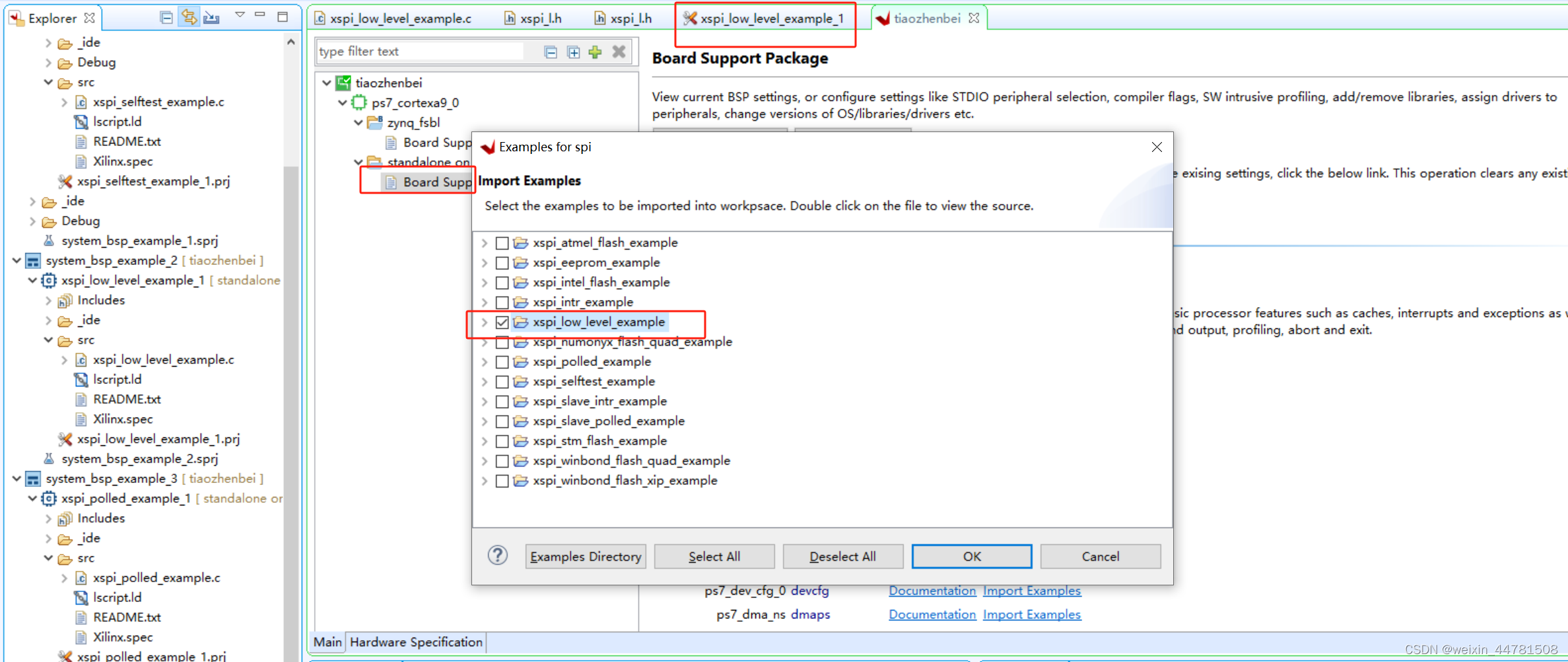
如前人工作,在Navigate to BSP Settings中找到历例程
file:///F:/Xilinx/Vitis/2019.2/data/embeddedsw/XilinxProcessorIPLib/drivers/spi_v4_5/doc/html/api/example.html

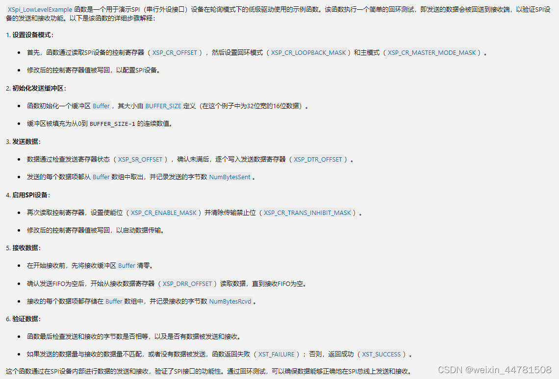
使用XSpi_LowLevelExample例子,源代码的AI解析
int XSpi_LowLevelExample(u32 BaseAddress)
{
	u32 Control;
	int NumBytesSent = 0;
	int NumBytesRcvd = 0;
	u32 Count;

	/*
	 * Set up the device in loopback mode and enable master mode.
	 */
	Control = XSpi_ReadReg(BaseAddress, XSP_CR_OFFSET);
	Control |= (XSP_CR_MASTER_MODE_MASK); // Enable master mode
	XSpi_WriteReg(BaseAddress, XSP_CR_OFFSET, Control);
代码中,摁住ctrl+左键 可以跳转到函数的定义,XSpi_ReadReg 就是寄存器读,通过基地址+偏移地址。
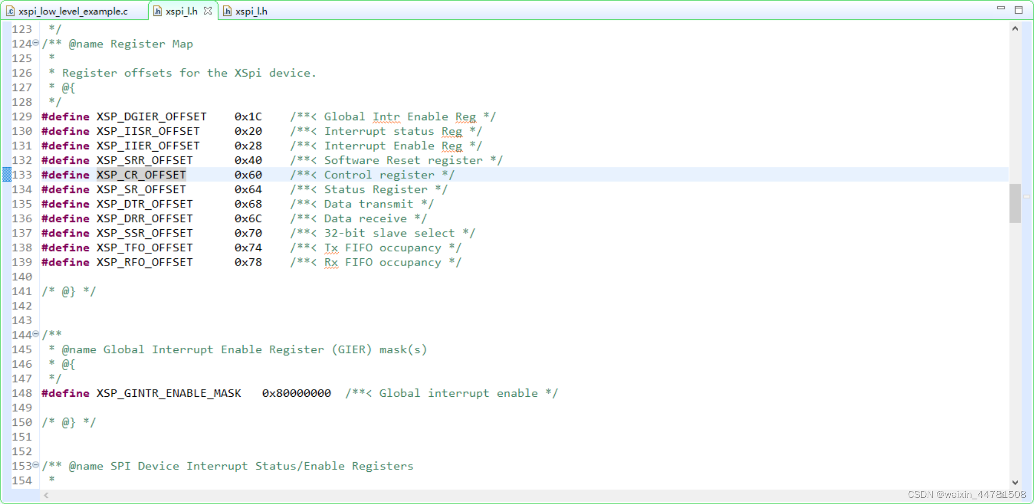
在xspi_h.c
#define XSP_DGIER_OFFSET 0x1C /**< Global Intr Enable Reg */
#define XSP_IISR_OFFSET 0x20 /**< Interrupt status Reg */
#define XSP_IIER_OFFSET 0x28 /**< Interrupt Enable Reg */
#define XSP_SRR_OFFSET 0x40 /**< Software Reset register */
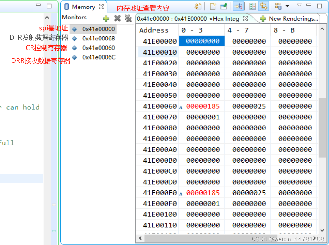
#define XSP_CR_OFFSET 0x60 /**< Control register */
#define XSP_SR_OFFSET 0x64 /**< Status Register */
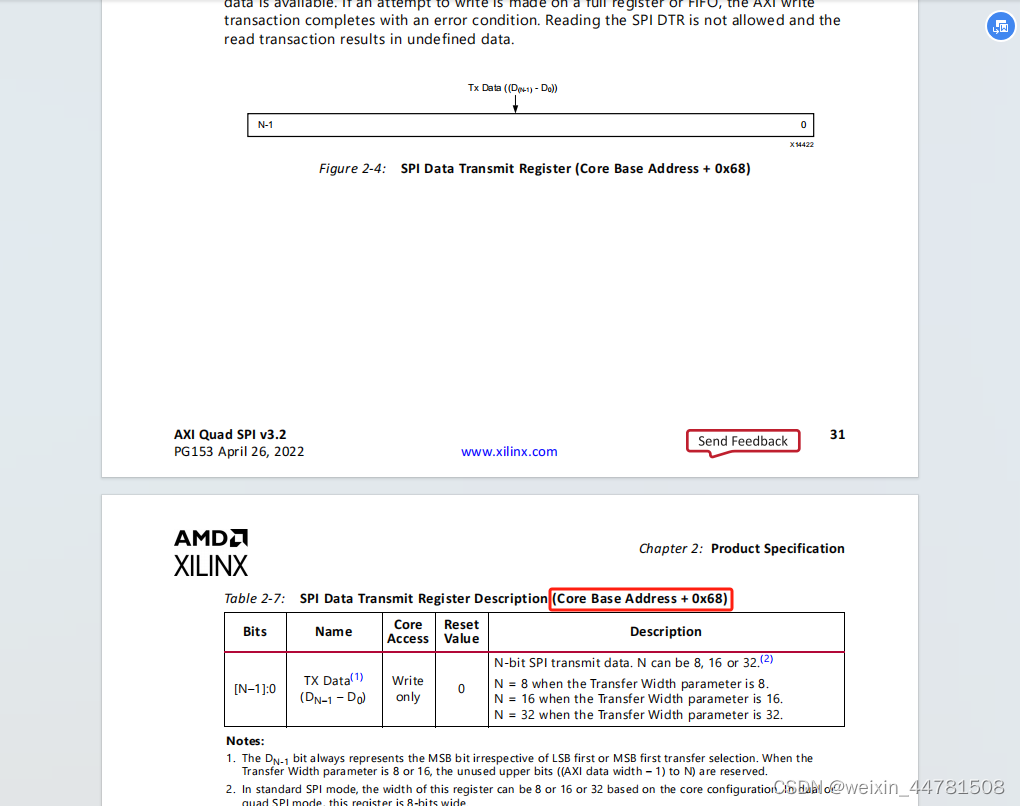
#define XSP_DTR_OFFSET 0x68 /**< Data transmit */
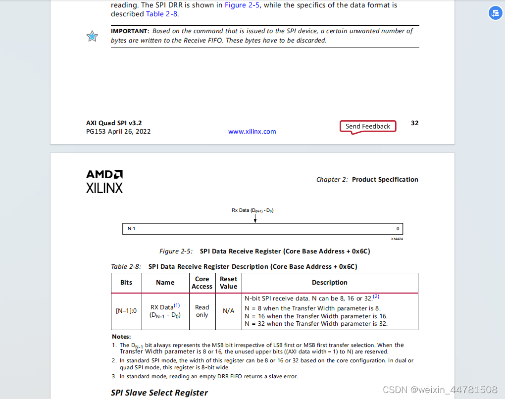
#define XSP_DRR_OFFSET 0x6C /**< Data receive */
#define XSP_SSR_OFFSET 0x70 /**< 32-bit slave select */
#define XSP_TFO_OFFSET 0x74 /**< Tx FIFO occupancy */
#define XSP_RFO_OFFSET 0x78 /**< Rx FIFO occupancy */
u8 Buffer[BUFFER_SIZE];// change to u8
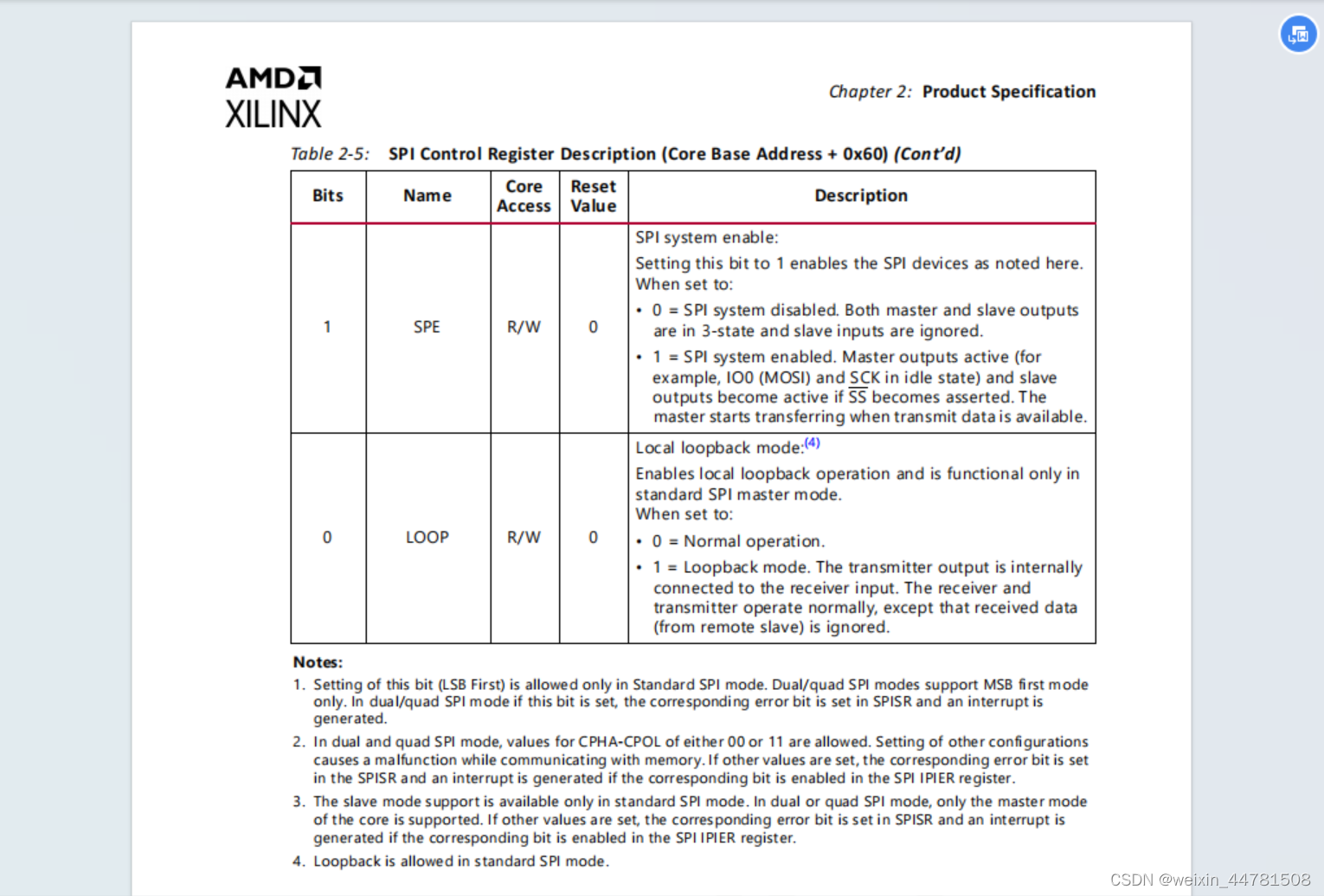
#define XSP_CR_OFFSET 0x60 /**< Control register */
【pg153-axi-quad-spi.pdf】网上找
60h是cr寄存器
最低位,LOOP 是否回环,默认0,不回环
	/*
	 * Set up the device in loopback mode and enable master mode.
	 */
	Control = XSpi_ReadReg(BaseAddress, XSP_CR_OFFSET);
	Control |= (XSP_CR_MASTER_MODE_MASK); // Enable master mode
	XSpi_WriteReg(BaseAddress, XSP_CR_OFFSET, Control);
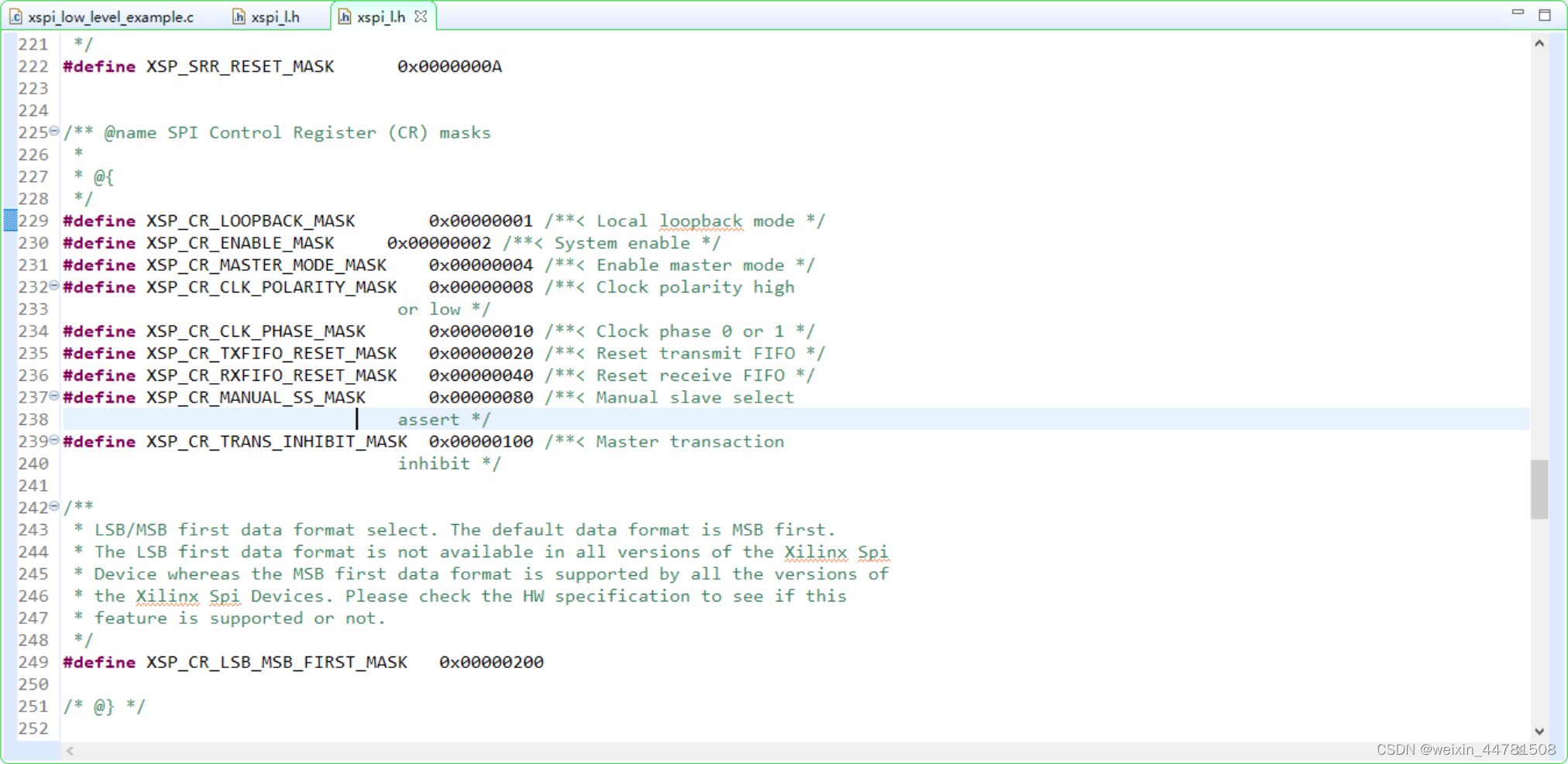
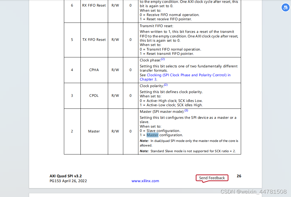
XSP_CR_MASTER_MODE_MASK 就代表把 Bits[2]给变成1
#define XSP_CR_LOOPBACK_MASK 0x00000001 /**< Local loopback mode */
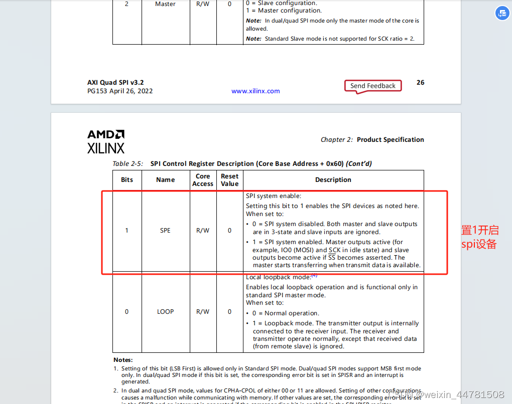
#define XSP_CR_ENABLE_MASK 0x00000002 /**< System enable */
#define XSP_CR_MASTER_MODE_MASK 0x00000004 /**< Enable master mode */
#define XSP_CR_CLK_POLARITY_MASK 0x00000008 /**< Clock polarity high
or low */
#define XSP_CR_CLK_PHASE_MASK 0x00000010 /**< Clock phase 0 or 1 */
#define XSP_CR_TXFIFO_RESET_MASK 0x00000020 /**< Reset transmit FIFO */
#define XSP_CR_RXFIFO_RESET_MASK 0x00000040 /**< Reset receive FIFO */
#define XSP_CR_MANUAL_SS_MASK 0x00000080 /**< Manual slave select
assert */
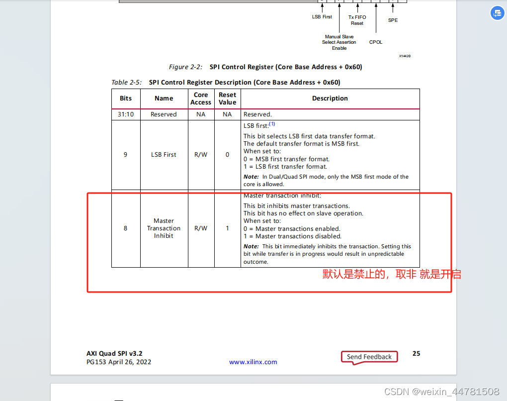
#define XSP_CR_TRANS_INHIBIT_MASK 0x00000100 /**< Master transaction
inhibit */
/*
* Fill up the transmitter with data, assuming the receiver can hold
* the same amount of data.
*/
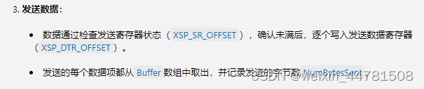
while ((XSpi_ReadReg(BaseAddress, XSP_SR_OFFSET) &
XSP_SR_TX_FULL_MASK) == 0) {
XSpi_WriteReg((BaseAddress), XSP_DTR_OFFSET,
Buffer[NumBytesSent++]);
}
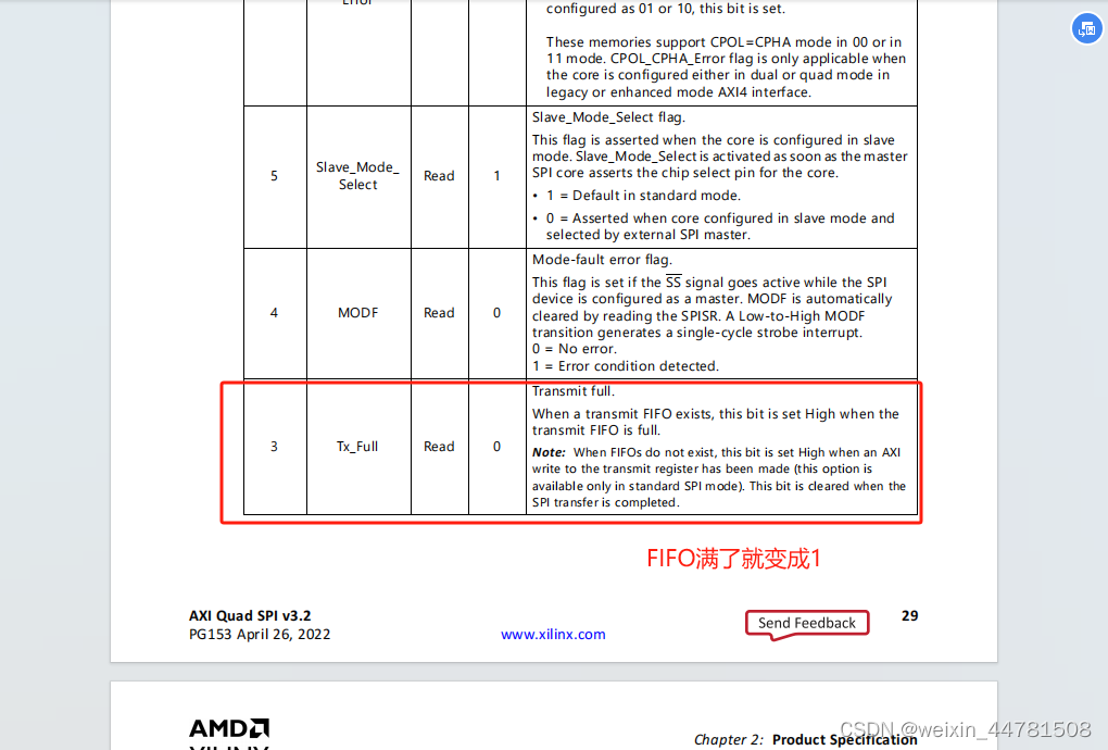
#define XSP_SR_TX_FULL_MASK 0x00000008 /**< Transmit Reg/FIFO is full */
SR状态寄存器,读取SR寄存器32bit内容
当发射tx 的fifo没有满的时候,把发射数据写进去
#define XSP_DTR_OFFSET 0x68 /**< Data transmit */
/*
* Enable the device.
*/
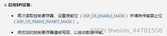
Control = XSpi_ReadReg(BaseAddress, XSP_CR_OFFSET);
Control |= XSP_CR_ENABLE_MASK;
Control &= ~XSP_CR_TRANS_INHIBIT_MASK;
XSpi_WriteReg(BaseAddress, XSP_CR_OFFSET, Control);
开启设备
清除传输禁止位
	/*
	 * Initialize the buffer with zeroes so that it can be used to receive
	 * data.
	 */
	for (Count = 0; Count < BUFFER_SIZE; Count++) {
		Buffer[Count] = 0x0;
	}
	/*
	 * Wait for the transmit FIFO to transition to empty before checking
	 * the receive FIFO, this prevents a fast processor from seeing the
	 * receive FIFO as empty
	 */
	while (!(XSpi_ReadReg(BaseAddress, XSP_SR_OFFSET) &
					XSP_SR_TX_EMPTY_MASK));
循环读取SR状态寄存器,看tx数据是不是空
/*
* Transmitter is full, now receive the data just looped back until
* the receiver is empty.
*/
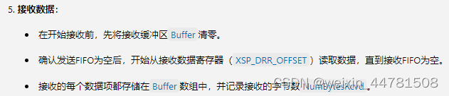
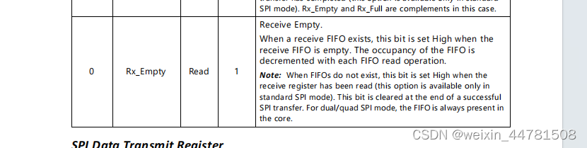
while ((XSpi_ReadReg(BaseAddress, XSP_SR_OFFSET) &
XSP_SR_RX_EMPTY_MASK) == 0) {//when RX fifo is no empty
Buffer[NumBytesRcvd++] = XSpi_ReadReg((BaseAddress),
XSP_DRR_OFFSET);
}
如果接收的寄存器不是空的了,(说明有数据来了),就把DRR接收data寄存器的数据读到fifo缓存里面。
流程:
1.设置控制寄存器CR,设置模式
2.定义缓存fifo
3.检查状态寄存器SR,把缓存fifo发到tx的data寄存器(DTR)
4.开启spi设备,CR使能,CR清楚禁止位
5.接收数据
6.验证数据
**
- 调试验证
**

开始调试
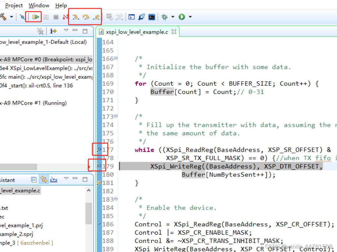
在代码里面打断点
右侧代码行双击 打断点
/******************************************************************************
*
* Copyright (C) 2002 - 2019 Xilinx, Inc.  All rights reserved.
*
* Permission is hereby granted, free of charge, to any person obtaining a copy
* of this software and associated documentation files (the "Software"), to deal
* in the Software without restriction, including without limitation the rights
* to use, copy, modify, merge, publish, distribute, sublicense, and/or sell
* copies of the Software, and to permit persons to whom the Software is
* furnished to do so, subject to the following conditions:
*
* The above copyright notice and this permission notice shall be included in
* all copies or substantial portions of the Software.
*
* THE SOFTWARE IS PROVIDED "AS IS", WITHOUT WARRANTY OF ANY KIND, EXPRESS OR
* IMPLIED, INCLUDING BUT NOT LIMITED TO THE WARRANTIES OF MERCHANTABILITY,
* FITNESS FOR A PARTICULAR PURPOSE AND NONINFRINGEMENT. IN NO EVENT SHALL
* THE AUTHORS OR COPYRIGHT HOLDERS BE LIABLE FOR ANY CLAIM, DAMAGES OR OTHER
* LIABILITY, WHETHER IN AN ACTION OF CONTRACT, TORT OR OTHERWISE, ARISING FROM,
* OUT OF OR IN CONNECTION WITH THE SOFTWARE OR THE USE OR OTHER DEALINGS IN
* THE SOFTWARE.
*
*
*
******************************************************************************/
/******************************************************************************/
/**
* @file  xspi_low_level_example.c
*
* This file contains a design example using the low-level driver of the
* SPI driver (XSpi). These macros are found in xspi_l.h.  A simple loopback
* test is done within an SPI device in polled mode. This example works only with
* 8-bit wide data transfers.
*
* @note
* This example works only with 8-bit wide data transfers in standard SPI mode.
* This example will not work if the axi_qspi device is confiured in dual/quad
* modes.
*
* To make this example work for 16 bit transfers change u8 Buffer[BUFFER_SIZE]
* to u16 Buffer[BUFFER_SIZE]. The SPI Core should also be configured for 16 bit
* access during the build time.
*
* To make this example work for 32 bit transfers change u8 Buffer[BUFFER_SIZE]
* to u32 Buffer[BUFFER_SIZE]. The SPI Core should also be configured for 32 bit
* access during the build time.
*
*
*<pre>
* MODIFICATION HISTORY:
*
* Ver   Who  Date     Changes
* ----- ---- -------- ----------------------------------------------------------
* 1.00b rpm  04/24/02 First release
* 1.00b jhl  09/10/02 Added code to ensure it works with a fast processor.
* 1.00b sv   05/16/05 Minor changes to comply to Doxygen and coding guidelines
* 3.00a ktn  10/28/09 Converted all register accesses to 32 bit access.
* 3.02a sdm  05/04/11 Added a note about dual/quad modes in axi_qspi.
* 4.2   ms   01/23/17 Added xil_printf statement in main function to
*                     ensure that "Successfully ran" and "Failed" strings
*                     are available in all examples. This is a fix for
*                     CR-965028.
*
*</pre>
*******************************************************************************/

/***************************** Include Files **********************************/

#include "xparameters.h"
#include "xstatus.h"
#include "xspi_l.h"
#include "xil_printf.h"

#include "stdio.h"
/************************** Constant Definitions ******************************/

/*
 * The following constants map to the XPAR parameters created in the
 * xparameters.h file. They are defined here such that a user can easily
 * change all the needed parameters in one place.
 */
#define SPI_BASEADDR		XPAR_SPI_0_BASEADDR

/**************************** Type Definitions ********************************/


/***************** Macros (Inline Functions) Definitions **********************/


/************************** Function Prototypes *******************************/

int XSpi_LowLevelExample(u32 BaseAddress);

/************************** Variable Definitions ******************************/


/*
 *  This is the size of the buffer to be transmitted/received in this example.
 */
#define BUFFER_SIZE			 32

/*
 * The buffer used for Transmission/Reception of the SPI test data
 */
u32 Buffer[BUFFER_SIZE];// change to u32

/******************************************************************************/
/**
* This function is the main function of the SPI Low Level example.
*
* @param	None
*
* @return	XST_SUCCESS to indicate success, else XST_FAILURE to indicate
*		Failure.
*
* @note		None
*
*******************************************************************************/
int main(void)
{
	int Status;

	/*
	 * Run the example, specify the Base Address that is generated in
	 * xparameters.h
	 */
	Status = XSpi_LowLevelExample(SPI_BASEADDR);
	if (Status != XST_SUCCESS) {
		xil_printf("Spi lowlevel Example Failed\r\n");
		printf("Spi lowlevel Example Failed\r\n");
		return XST_FAILURE;
	}

	xil_printf("Successfully ran Spi lowlevel Example\r\n");
	printf("Successfully ran Spi lowlevel Example\r\n");
	return XST_SUCCESS;
}

/******************************************************************************/
/**
*
* This function does a simple loopback test within an SPI device.
*
* @param	BaseAddress is the BaseAddress of the SPI device
*
* @return	XST_SUCCESS if successful, XST_FAILURE if unsuccessful
*
* @note		None
*
*******************************************************************************/
int XSpi_LowLevelExample(u32 BaseAddress)
{
	u32 Control;
	int NumBytesSent = 0;
	int NumBytesRcvd = 0;
	u32 Count;

	/*
	 * Set up the device in loopback mode and enable master mode.
	 */
	Control = XSpi_ReadReg(BaseAddress, XSP_CR_OFFSET);
	Control |= (XSP_CR_LOOPBACK_MASK | XSP_CR_MASTER_MODE_MASK); // Enable master mode
	XSpi_WriteReg(BaseAddress, XSP_CR_OFFSET, Control);


	/*
	 * Initialize the buffer with some data.
	 */
	for (Count = 0; Count < BUFFER_SIZE; Count++) {
		Buffer[Count] = Count;// 0-31
	}

	/*
	 * Fill up the transmitter with data, assuming the receiver can hold
	 * the same amount of data.
	 */
	while ((XSpi_ReadReg(BaseAddress, XSP_SR_OFFSET) &
			XSP_SR_TX_FULL_MASK) == 0) {//when TX fifo is not full
		XSpi_WriteReg((BaseAddress), XSP_DTR_OFFSET,
				Buffer[NumBytesSent++]);
	}

	/*
	 * Enable the device.
	 */
	Control = XSpi_ReadReg(BaseAddress, XSP_CR_OFFSET);
	Control |= XSP_CR_ENABLE_MASK;
	Control &= ~XSP_CR_TRANS_INHIBIT_MASK;
	XSpi_WriteReg(BaseAddress, XSP_CR_OFFSET, Control);

	/*
	 * Initialize the buffer with zeroes so that it can be used to receive
	 * data.
	 */
	for (Count = 0; Count < BUFFER_SIZE; Count++) {
		Buffer[Count] = 0x0;
	}

	/*
	 * Wait for the transmit FIFO to transition to empty before checking
	 * the receive FIFO, this prevents a fast processor from seeing the
	 * receive FIFO as empty
	 */
	while (!(XSpi_ReadReg(BaseAddress, XSP_SR_OFFSET) &
					XSP_SR_TX_EMPTY_MASK));

	/*
	 * Transmitter is full, now receive the data just looped back until
	 * the receiver is empty.
	 */
	while ((XSpi_ReadReg(BaseAddress, XSP_SR_OFFSET) &
			XSP_SR_RX_EMPTY_MASK) == 0) {//when RX fifo is no empty
		Buffer[NumBytesRcvd++] = XSpi_ReadReg((BaseAddress),
						XSP_DRR_OFFSET);
	}

	/*
	 * If no data was sent or the data that was sent was not received,
	 * then return an error
	 */
	if ((NumBytesSent != NumBytesRcvd) || (NumBytesSent == 0)) {
		return XST_FAILURE;
	}

	return XST_SUCCESS;
}