目录
实验要求:
实验过程:
一:首先设计实验
二:IP地址的划分(基于192.168.1.0/24)
在ensp中对路由器的相关命令进行配置:
三:配IP地址
(1)首先给所有设备配置环回IP(用户网段)地址:
(2)配置路由之间骨干链路的IP:
(3)给PC端配置IP地址(使用dhcp服务):
四:配置缺省路由(R6为公网处于该网络的边界位置)
(1)手动配置缺省
(2)添加路由(预防路由环路,便于部署管理路由)
五:避免环路(要求5、选路最佳,路由表尽量小,避免环路;)
六:实现NAT连接(要求6、R1-R5均可以访问R6的环回;)
七:Telnet远程连接,端口映射(要求:7、R6 telnet R5的公有地址时,实际登录到R1上;)
八:修改链路优先级(要求8、R4与R5正常通过1000M链路,故障时通过100m链路)
实验要求:
1、R6为ISP,接口IP地址均为公有地址,该设备只能配置IP地址,之后不能再对其进行任何配置;
2、R1-R5为局域网,私有IP地址192.168.1.0/24,请合理分配;
3、R1、R2、R4,各有两个环回IP地址;R5,R6各有一个环回地址;所有路由器上环回均代表连接用户的接口;
4、R3下面的两台PC通过DHCP自动获取IP地址;
5、选路最佳,路由表尽量小,避免环路;
6、R1-R5均可以访问R6的环回;
7、R6 telnet R5的公有地址时,实际登录到R1上;
8、R4与R5正常通过1000M链路,故障时通过100m链路;
实验过程:
一:首先设计实验
从图中和实验要求12中我们可以看出这个拓扑结构是一个从R5开始局域网(公网)和公网,在做实验的过程中我们要考虑一些拓扑结构的省略,比如我们配好IP地址过后可以将我们的R4到R5的100M的连线和R5与R6的连线先down了,减少我们实验的复杂性(尽可能的去简化我们的拓扑结构)。
二:IP地址的划分(基于192.168.1.0/24)
为了我们实验的便利性,在配置IP地址的时候我们要考虑以下几个方面:
- 要尽可能的节省IP地址;
- 要便于我们进行汇总减少我们的出错情况;
- 网段的划分要合理,如该实验中我们需要划分14个网段,但是实际划分的网段要比我们需要的网段要稍多一些(作为保留地址)避免故障发生。
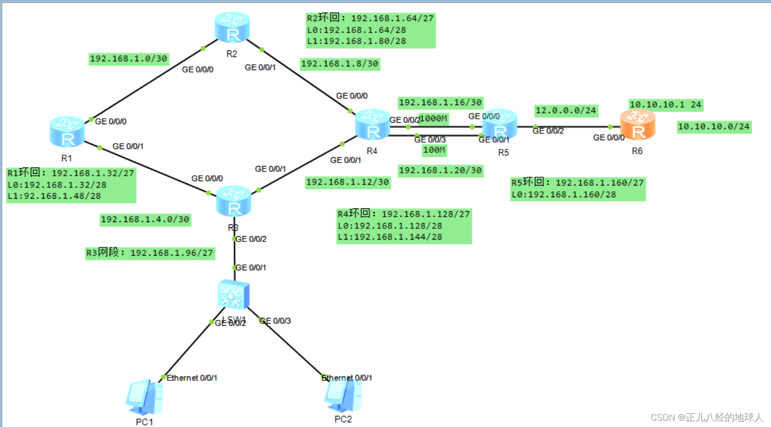
路由器之间的网段划分:
192.168.1.000 00000 /27 ----- 总线链路(骨干链路)
192.168.1.000 000 00 /30 ---- 192.168.1.0/3
192.168.1.000 001 00 /30 --- 192.168.1.4/30
192.168.1.000 010 00 /30 ---- 192.168.1.8/30
192.168.1.000 011 00 /30 ---- 192.168.1.12/30
192.168.1.000 100 00 /30 ---- 192.168.1.16/30
192.168.1.000 101 00 /30 ---- 192.168.1.20/30
# 192.168.1.000 110 00 /30 ----192.168.1.25/30
# 192.168.1.000 111 00 /30 ----192.168.1.31/30 (多余的的2条网段备用)
R1-R5上环回地址的分配:
192.168.1.001 00000 /27 ---- R1 192.168.1.32/27 [R1环回(2)]
192.168.1.001 0 0000 /28 --- 192.168.1.32/28
192.168.1.001 1 0000 /28 --- 192.168.1.48/28
192.168.1.010 00000 /27 ---- R2 192.168.1.64/27 [R2环回(2)]
192.168.1.010 0 0000 /28 ---- 192.168.1.64/28
192.168.1.010 1 0000 /28 ---- 192.168.1.80/28
192.168.1.011 00000 /27 ---- R3 192.168.1.96/27 [R3,(下面PC由dhcp服务获取ip地址)]
192.168.1.100 00000 /27 ---- R4 192.168.1.128/27 [R4环回(2)]
192.168.1.100 0 0000 /28 ---- 192.168.1.128/28
192.168.1.100 1 0000 /28 ---- 192.168.1.144/28
192.168.1.101 00000 /27 ---- R5 192.168.1.160/27 [R5环回(1)]
192.168.1.101 0 0000 ---- 192.168.1.160/28
192.168.1.110 00000 /27
192.168.1.111 00000 /27(多余的2条IP地址,为预留备用)
R5 与R6上的链路网段:12.0.0.0/24
R6的环回地址为10.10.10.0/24
所有的网段和IP地址分配如下图:
在ensp中对路由器的相关命令进行配置:
三:配IP地址
(1)首先给所有设备配置环回IP(用户网段)地址:
R1:
<Huawei>sys

<Huawei>system-view

[Huawei]sysname R1

[R1]

[R1]interface LoopBack 0

[R1-LoopBack0]

[R1-LoopBack0]ip address 192.168.1.33 28{32为网络号,可用ip要加1}

[R1-LoopBack0]q

[R1]interface LoopBack 1

[R1-LoopBack1]ip address 192.168.1.49 28

[R1-LoopBack1]q

[R1]
R2:
<Huawei>sys

[Huawei]sysname R2

[R2]

[R2]interface LoopBack 0

[R2-LoopBack0]ip add 192.168.1.65 28

[R2-LoopBack0]q

[R2]interface LoopBack 1

[R2-LoopBack1]ip add 192.168.1.81 28

[R2-LoopBack1]q

[R2]
R3:
<Huawei>sys

[Huawei]sysname R3

[R3]

[R3]un info en

Info: Information center is disabled.

[R3]int g0/0/2

[R3-GigabitEthernet0/0/2]ip add 192.168.1.97 27

[R3-GigabitEthernet0/0/2]q

[R3]
R4:
<Huawei>sys

[Huawei]sysname

[Huawei]sysname R4

[R4]interface LoopBack 0

[R4-LoopBack0]ip add 192.168.1.129 28

[R4-LoopBack0]q

[R4]interface LoopBack 1

[R4-LoopBack1]ip add 192.168.1.145 28

[R4-LoopBack1]q

[R4]
R5:
<Huawei>sys

[Huawei]sysname R5

[R5]interface LoopBack 0

[R5-LoopBack0]ip add 192.168.1.161 27

[R5-LoopBack0]q

[R5]
R6:
<Huawei>sys

[Huawei]sysname R6

[R6]interface LoopBack 0

[R6-LoopBack0]ip add 10.10.10.1 24

[R6-LoopBack0]q

[R6]
(2)配置路由之间骨干链路的IP:
R1:
<R1>sys

[R1]interface g0/0/0

[R1-GigabitEthernet0/0/0]ip add 192.168.1.1 30

[R1-GigabitEthernet0/0/0]q

[R1]int g0/0/1

[R1-GigabitEthernet0/0/1]ip add 192.168.1.5 30

[R1-GigabitEthernet0/0/1]q

[R1]
R2:
<R2>sys

[R2]int g0/0/1

[R2-GigabitEthernet0/0/1]ip add 192.168.1.9 30

[R2-GigabitEthernet0/0/1]q

[R2]int g0/0/0

[R2-GigabitEthernet0/0/0]ip add 192.168.1.2 30

[R2-GigabitEthernet0/0/0]q

[R2]
R3:
<R3>sys

[R3]int g0/0/0

[R3-GigabitEthernet0/0/0]ip add 192.168.1.6 30

[R3-GigabitEthernet0/0/0]q

[R3]int g0/0/1

[R3-GigabitEthernet0/0/1]ip add 192.168.1.13 30

[R3-GigabitEthernet0/0/1]q

[R3]
R4:
<R4>sys

[R4]int g0/0/0

[R4-GigabitEthernet0/0/0]ip add 192.168.1.10 30

[R4-GigabitEthernet0/0/0]q

[R4]int g0/0/1

[R4-GigabitEthernet0/0/1]ip add 192.168.1.14 30

[R4-GigabitEthernet0/0/1]q

[R4]int g0/0/2

[R4-GigabitEthernet0/0/2]ip add 192.168.1.17 30

[R4-GigabitEthernet0/0/2]q

[R4]int g0/0/3

[R4-GigabitEthernet0/0/3]ip add 192.168.1.21 30

[R4-GigabitEthernet0/0/3]q

[R4]
R5:
<R5>

<R5>sys

[R5]int g0/0/0

[R5-GigabitEthernet0/0/0]ip add 192.168.1.18 30

[R5-GigabitEthernet0/0/0]q

[R5]int g0/0/1

[R5-GigabitEthernet0/0/1]ip add 192.168.1.22 30

[R5-GigabitEthernet0/0/1]q

[R5]int g0/0/2

[R5-GigabitEthernet0/0/2]ip add 12.0.0.1 24

[R5-GigabitEthernet0/0/2]q

[R5]
R6:
<R6>sys

[R6]int g0/0/0

[R6-GigabitEthernet0/0/0]ip add 12.0.0.2 24

[R6-GigabitEthernet0/0/0]q

[R6]
(3)给PC端配置IP地址(使用dhcp服务):
<R3>sys

[R3]dhcp ena

[R3]dhcp enable

[R3]ip pool a

[R3-ip-pool-a]network 192.168.1.96 mask 27

[R3-ip-pool-a]gateway-list 192.168.1.97

[R3-ip-pool-a]dns-list 114.114.114.114 8.8.8.8

[R3-ip-pool-a]q

[R3]int g0/0/2

[R3-GigabitEthernet0/0/2]dhcp select global
然后在实验拓扑图中对PC1与PC2启动dhcp服务,再在命令行中ipconfig查看动态分配的ip地址


PC1:192.168.1.126
PC2:192.168.1.125
PS:配置好这些后要检查一下ip有没有配错的,网段之间是否能够ping通,以防马虎而导致影响了后面的实验进程,再一个就是后面实验过程中出错了排错就很是麻烦。
举例:
检查下R1所有网段用户的ip是否正确:
[R1]display ip interface brief

(这里只保留需要检查的信息)

Interface                         IP Address/Mask      Physical   Protocol

GigabitEthernet0/0/0              192.168.1.1/30       up         up

GigabitEthernet0/0/1              192.168.1.5/30       up         up

LoopBack0                         192.168.1.33/28      up         up(s)

LoopBack1                         192.168.1.49/28      up         up(s)

NULL0                             unassigned           up         up(s)

[R1]

Ping测试:

R1对R2:

[R1]ping 192.168.1.2

  PING 192.168.1.2: 56  data bytes, press CTRL_C to break

0.00% packet loss

R1对R3:

[R1]ping 192.168.1.6

  PING 192.168.1.6: 56  data bytes, press CTRL_C to break

    0.00% packet loss

R4对R2:

[R4]ping 192.168.1.9

  PING 192.168.1.9: 56  data bytes, press CTRL_C to break

    0.00% packet loss

R4对R3:

[R4]ping 192.168.1.13

  PING 192.168.1.13: 56  data bytes, press CTRL_C to break

0.00% packet loss

R4对R5:

[R4]ping 192.168.1.18

  PING 192.168.1.18: 56  data bytes, press CTRL_C to break

    0.00% packet loss


[R4]ping 192.168.1.22

  PING 192.168.1.22: 56  data bytes, press CTRL_C to break

    0.00% packet loss

R5对R6:

[R5]ping 12.0.0.2

  PING 12.0.0.2: 56  data bytes, press CTRL_C to break

    0.00% packet loss
所以由以上的测试我们可以得知各路由网段之间是互通的
四:配置缺省路由(R6为公网处于该网络的边界位置)
(1)手动配置缺省
R1:

[R1]ip route-static 0.0.0.0 0 192.168.1.2

[R1]ip route-static 0.0.0.0 0 192.168.1.6

R2:

[R2]ip route-static 0.0.0.0 0 192.168.1.10

R3:

[R3]ip route-static 0.0.0.0 0 192.168.1.14

R4:

[R4]ip route-static 0.0.0.0 0 192.168.1.18

R5:

[R5]ip route-static 0.0.0.0 0 12.0.0.2
(2)添加路由(预防路由环路,便于部署管理路由)
R1:

[R1]ip route-static 192.168.1.64 27 192.168.1.2

[R1]ip route-static 192.168.1.8 30 192.168.1.2

[R1]ip route-static 192.168.1.96 27 192.168.1.6

[R1]ip route-static 192.168.1.12 30 192.168.1.6

R2:

[R2]ip route-static 192.168.1.32 27 192.168.1.1

[R2]ip route-static 192.168.1.4 30 192.168.1.1

[R2]ip route-static 192.168.1.96 27 192.168.1.1

[R2]ip route-static 192.168.1.96 27 192.168.1.10

R3:

[R3]ip route-static 192.168.1.32 27 192.168.1.5

[R3]ip route-static 192.168.1.0 30 192.168.1.5

[R3]ip route-static 192.168.1.64 27 192.168.1.5

[R3]ip route-static 192.168.1.64 27 192.168.1.14

R4:

[R4]ip route-static 192.168.1.64 27 192.168.1.9

[R4]ip route-static 192.168.1.0 30 192.168.1.9

[R4]ip route-static 192.168.1.32 27 192.168.1.9

[R4]ip route-static 192.168.1.32 27 192.168.1.13

[R4]ip route-static 192.168.1.4 30 192.168.1.13

[R4]ip route-static 192.168.1.96 27 192.168.1.13


R5:

[R5]ip route-static 192.168.1.32 27 192.168.1.17

[R5]ip route-static 192.168.1.64 27 192.168.1.17

[R5]ip route-static 192.168.1.96 27 192.168.1.17

[R5]ip route-static 192.168.1.128 27 192.168.1.17

[R5]ip route-static 192.168.1.0 30 192.168.1.17

[R5]ip route-static 192.168.1.4 30 192.168.1.17

[R5]ip route-static 192.168.1.8 30 192.168.1.17

[R5]ip route-static 192.168.1.12 30 192.168.1.17
在此简单的使用R1去测试一下网络连接是否通
举例:1、R1去ping R5上面的环回地址

[R1]ping 192.168.1.161

  PING 192.168.1.161: 56  data bytes, press CTRL_C to break

    0.00% packet loss

R5去ping PC2
[R5]ping 192.168.1.125

  PING 192.168.1.125: 56  data bytes, press CTRL_C to break

0.00% packet loss
测试通过!!!
到此我们已经完成了要求中的1~4啦!!
五:避免环路(要求5、选路最佳,路由表尽量小,避免环路;)
[R1]ip route-static 192.168.1.32 27 NULL 0

[R2]ip route-static 192.168.1.64 27 NULL 0

[R4]ip route-static 192.168.1.128 27 NULL 0
六:实现NAT连接(要求6、R1-R5均可以访问R6的环回;)
[R5]acl 2000

[R5-acl-basic-2000]rule permit source 192.168.1.0 0.0.0.255

[R5-acl-basic-2000]q

[R5]int g0/0/2

[R5-GigabitEthernet0/0/2]nat outbound 2000
七:Telnet远程连接,端口映射(要求:7、R6 telnet R5的公有地址时,实际登录到R1上;)
[R1-aaa]display user-interface  (查看我的用户权限为3)

  Idx  Type     Tx/Rx      Modem Privi ActualPrivi Auth  Int

+ 0    CON 0    9600       -     3     3           N     -

设置aaa模式:

[R1]aaa

[R1-aaa]local-user gxc privilege level 3 password cipher 123456

Info: Add a new user.

启动R1 telnet服务:

[R1-aaa]local-user gxc service-type telnet

[R1]user-interface vty 0 4

[R1-ui-vty0-4]authentication-mode aaa

R5的端口映射:

[R5]int g0/0/2

[R5-GigabitEthernet0/0/2]nat static protocol tcp global current-interface 23 ins

ide  192.168.1.33 23

Warning:The port 23 is well-known port. If you continue it may cause function fa

ilure.

Are you sure to continue?[Y/N]:y

启动R5 telnet服务:

[R5]aaa

[R5-aaa]local-user gxc privilege level 3 password cipher 123456

Info: Add a new user.

[R5-aaa]local-user gxc service-type telnet

[R5-aaa]q

[R5]user-interface vty 0 4

[R5-ui-vty0-4]authentication-mode aaa

R6进行远程登录测试
八:修改链路优先级(要求8、R4与R5正常通过1000M链路,故障时通过100m链路)
[R4]ip route-static 0.0.0.0 0 192.168.1.22

[R4]ip route-static 0.0.0.0 0 192.168.1.22 preference 61


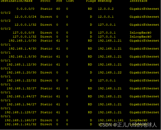
[R5]ip route-static 192.168.1.0 255.255.255.252 192.168.1.21 pre 61

[R5]ip route-static 192.168.1.4 255.255.255.252 192.168.1.21 pre 61

[R5]ip route-static 192.168.1.8 255.255.255.252 192.168.1.21 pre 61

[R5]ip route-static 192.168.1.12 255.255.255.252 192.168.1.21 pre 61

[R5]ip route-static 192.168.1.32 255.255.255.224 192.168.1.21 pre 61

[R5]ip route-static 192.168.1.64 255.255.255.224 192.168.1.21 pre 61

[R5]ip route-static 192.168.1.96 255.255.255.224 192.168.1.21 pre 61

[R5]ip route-static 192.168.1.128 255.255.255.224 192.168.1.21 pre 61

[R5]display ip routing-table
这是没有故障时连接走上面1000M的链路
(现在路由表中只显示优先级为60)
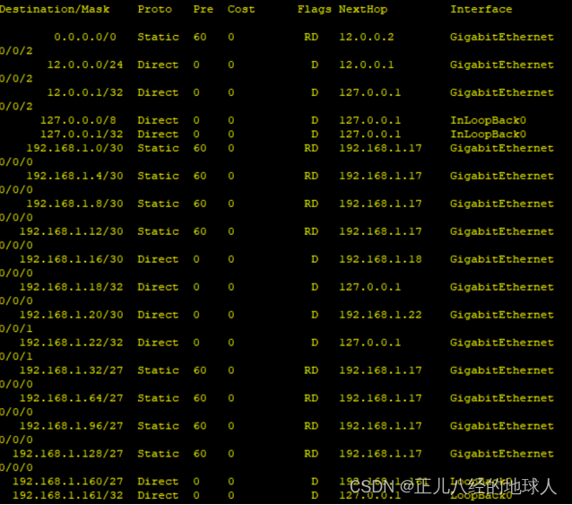
[R5-GigabitEthernet0/0/0]shutdown现在关闭R5 g0/0/0接口假设出现故障了,只能走下面100M的链路
(现在路由表中到R4的优先级为61)


![[HackMyVM] Quick](https://img-blog.csdnimg.cn/direct/6c324b3fe0d343f3bb8aad1d2f86219d.png)


