PWM驱动舵机

接线图如上图所示。注意,舵机的5V 线不能接到面包板上的正极,面包板上的正极只有3.3V,是STM32提供的,所以要接到STLINK的5V,
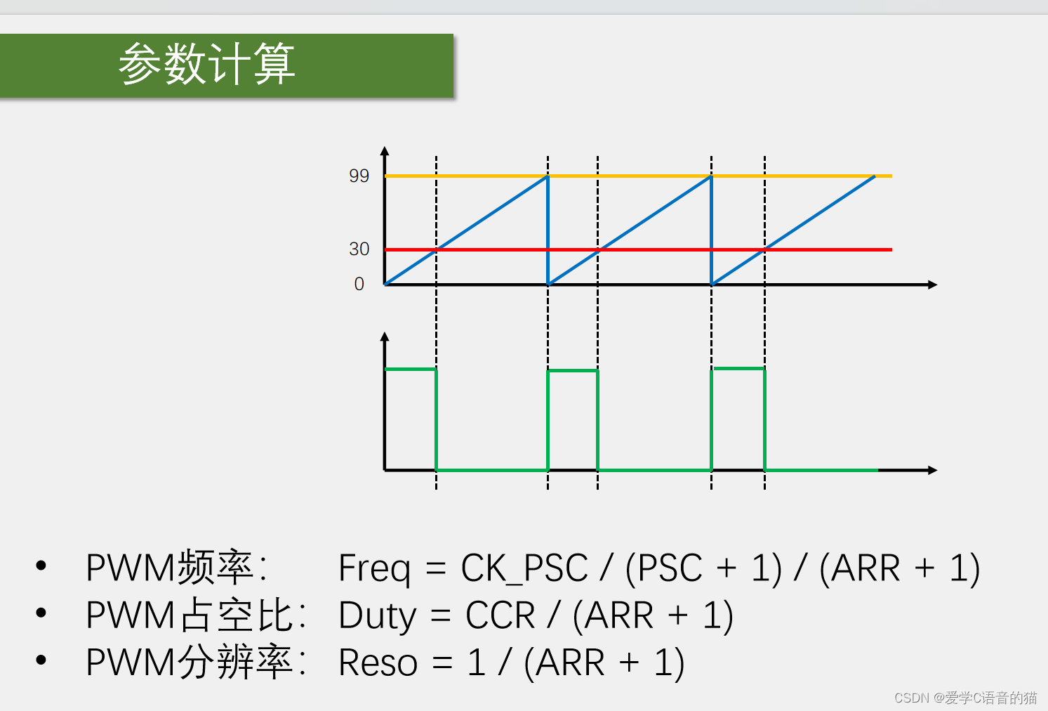
我们如何驱动舵机呢?由之前我们介绍原理知道,要输出如下图对应的PWM波形才行,只要你的波形能按照这个规定,准确的输出,就能驱动

在上次PWM驱动呼吸灯的基础上改一下,我们现在电路图连接的是PA1口的通道2,这里GPIO的初始化时,改为GPIO_Pin_1,可以从引脚定义表去看看,呼吸灯是使用PA0引脚,所以是定时器2的通道1,但是PA1是用的定时器2的通道2,所以要把TIM_OC1Init改为OC2.
TIM_OC2Init(TIM2,&TIM_OCInitStructure);
如果通道1和通道2都想用的话,就直接初始化两个通道,比如
TIM_OC2Init(TIM2,&TIM_OCInitStructure);

TIM_OC1Init(TIM2,&TIM_OCInitStructure);
这样就能同时使用两个通道来输出PWM了,同理,通道3与通道4也是可以使用的。
那对于同一个定时器的不同通道输出的PWM,他们的频率,因为不同通道是共用一个计数器的,所以他们的频率必须是一样的。它们的占空比,由各个的CCR决定,所以占空比可以各自设定,
还有它们的相位,由于计数器更新,所有PWM同时跳变,所以它们的相位是同步的。这就是同一个定时器不同通道输出PWM的特点,如果驱动多个舵机或者直流电机,那使用同一个定时器不同通道的PWM,就完全可以了。
最后,把改的CCR全部变为通道2.
然后根据舵机计算公式设置CCR,PSC,ARR.

最后代码如下:所用的所有模块如下

main.c
#include "stm32f10x.h"                  // Device header
#include "Delay.h"
#include "OLED.h"
#include "Servo.h"
#include "Key.h"

uint8_t KeyNum;
float Angle;

int main(void)
{
	OLED_Init();
	Servo_Init();
	Key_Init();

	OLED_ShowString(1, 1, "Angle:");

	while (1)
	{
		KeyNum = Key_GetNum();
		if (KeyNum == 1)
		{
			Angle += 30;
			if (Angle > 180)
			{
				Angle = 0;
			}
		}
		Servo_SetAngle(Angle);
		OLED_ShowNum(1, 7, Angle, 3);
	}
}
Servo.c
#include "stm32f10x.h"                  // Device header
#include "PWM.h"

void Servo_Init(void)
{
	PWM_Init();
}

void Servo_SetAngle(float Angle)
{
	PWM_SetCompare2(Angle / 180 * 2000 + 500);
}
Servo.h
#ifndef __SERVO_H
#define __SERVO_H

void Servo_Init(void);
void Servo_SetAngle(float Angle);

#endif
其他的模块都在前面的博客有,自己可以去找一下,后面我会全部整理在一起。
PWM驱动直流电机
接线图:

代码如下:
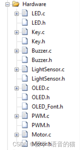
所有模块如下:
main.c
#include "stm32f10x.h"                  // Device header
#include "Delay.h"
#include "OLED.h"
#include "Motor.h"
#include "Key.h"

uint8_t KeyNum;
int8_t Speed;

int main(void)
{

	OLED_Init();
	Motor_Init();
	Key_Init();
	OLED_ShowString(1,1,"Speed:");


	while(1)
	{
      KeyNum=Key_GetNum();
		if(KeyNum==1)
		{
			Speed+=20;
			if(Speed>100)
			{
				Speed=-100;
			}
		}
		Motor_SetSpeed(Speed);
		OLED_ShowSignedNum(1,7,Speed,3);
	}
}
Mortor.c
#include "stm32f10x.h"                  // Device header
#include "PWM.h"


void Motor_Init(void)
{
	RCC_APB2PeriphClockCmd(RCC_APB2Periph_GPIOA, ENABLE);

	GPIO_InitTypeDef GPIO_InitStructure;
 	GPIO_InitStructure.GPIO_Mode = GPIO_Mode_Out_PP;
	GPIO_InitStructure.GPIO_Speed = GPIO_Speed_50MHz;
	GPIO_InitStructure.GPIO_Pin = GPIO_Pin_4|GPIO_Pin_5;//方向控制脚
 	GPIO_Init(GPIOA, &GPIO_InitStructure);

	PWM_Init();
}

void Motor_SetSpeed(int8_t Speed)
{
	if(Speed>=0)
	{
		GPIO_SetBits(GPIOA, GPIO_Pin_4);
		GPIO_ResetBits(GPIOA, GPIO_Pin_5);
		PWM_SetCompare3(Speed);
	}
	else
	{
		GPIO_ResetBits(GPIOA, GPIO_Pin_4);
		GPIO_SetBits(GPIOA, GPIO_Pin_5);
		PWM_SetCompare3(-Speed);
	}
}
Mortor.h
#ifndef __OLED_H
#define __OLED_H
void Motor_Init(void);
void Motor_SetSpeed(int8_t Speed);

#endif
