文章目录
- 前言
- 一、介绍部分
- 编码器简介
- 正交编码器
- 编码器接口基本结构
- 工作模式
- 均不反向实例
- 均反向实例
- 二、代码部分
- 编码器接口测速
- 连接线路
- 代码实现
前言
这部分主要介绍定时器编码器接口,了解使用编码器对计数器的控制,理解正交编码器的工作模式,通过编码器接口测试1s内的电平变化(相当于测速)。
一、介绍部分
编码器简介

正交编码器
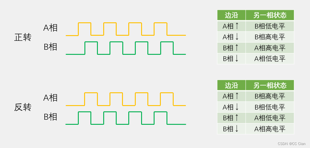
编码器接口基本结构
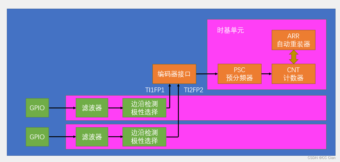
也就是定时器框图这部分,配置输入捕获的前半部分
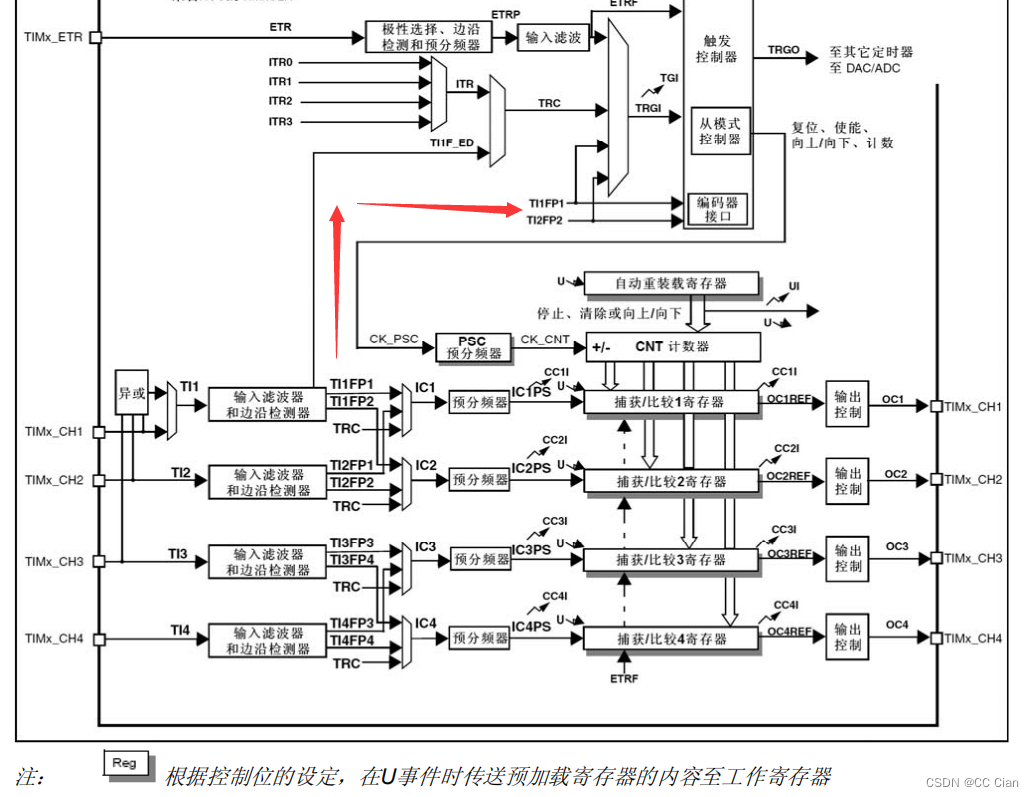
工作模式
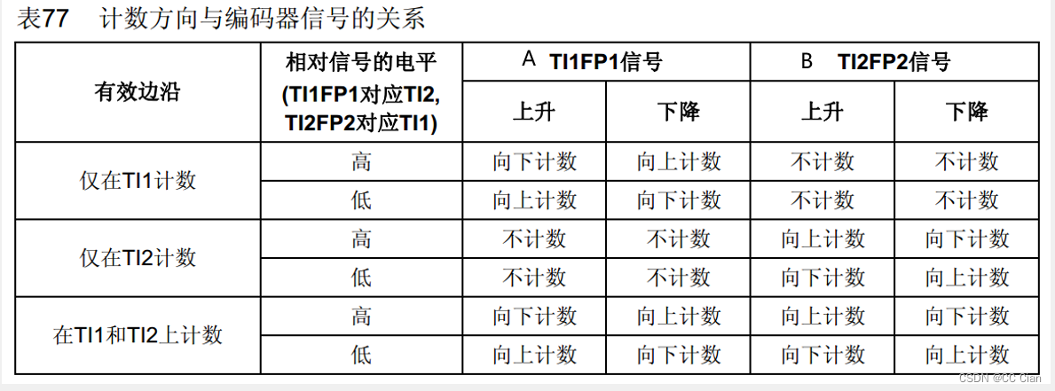
均不反向实例
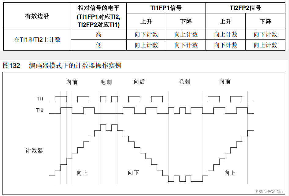
均反向实例
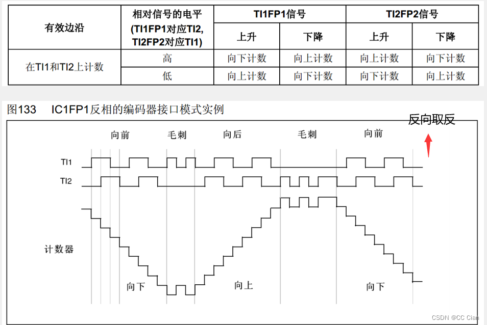
二、代码部分
编码器接口测速
连接线路

代码实现
封装编码器内容Encoder.c
#include "stm32f10x.h"                  // Device header

void Encoder_Init(void){
	// 初始化时钟
	RCC_APB1PeriphClockCmd(RCC_APB1Periph_TIM3,ENABLE);
	RCC_APB2PeriphClockCmd(RCC_APB2Periph_GPIOA, ENABLE);


	GPIO_InitTypeDef GPIO_InitStructure;
	GPIO_InitStructure.GPIO_Mode = GPIO_Mode_IPU;		// 上拉输出
	GPIO_InitStructure.GPIO_Pin = GPIO_Pin_6 | GPIO_Pin_7;
	GPIO_InitStructure.GPIO_Speed = GPIO_Speed_50MHz;		// 50Hz翻转速度
	GPIO_Init(GPIOA, &GPIO_InitStructure);


	// 配置事间基础(时基单元)
	TIM_TimeBaseInitTypeDef TIM_InitStructure;
	// 时钟分频
	TIM_InitStructure.TIM_ClockDivision = TIM_CKD_DIV1;
	// 计算模式
	TIM_InitStructure.TIM_CounterMode = TIM_CounterMode_Up;
	// 重载值(有1的偏差)<计数值> ARR
	TIM_InitStructure.TIM_Period = 65536-1;
	// 预分频(有1的偏差)<频率> PSC,被编码器接管
	TIM_InitStructure.TIM_Prescaler = 1-1;
	// 重复计数器(不使用)
	TIM_InitStructure.TIM_RepetitionCounter = 0;
	TIM_TimeBaseInit(TIM3,&TIM_InitStructure);

	//初始化输入捕获,均不反相
	TIM_ICInitTypeDef TIM_ICInitStructure;
	// 选择CH1通道
	TIM_ICInitStructure.TIM_Channel = TIM_Channel_1;
	TIM_ICInitStructure.TIM_ICFilter = 0xF;
	TIM_ICInitStructure.TIM_ICPolarity = TIM_ICPolarity_Rising;
	TIM_ICInitStructure.TIM_ICPrescaler = TIM_ICPSC_DIV1;
	TIM_ICInitStructure.TIM_ICSelection = TIM_ICSelection_DirectTI;
	TIM_ICInit(TIM3,&TIM_ICInitStructure);
	// 选择CH2通道
	TIM_ICInitStructure.TIM_Channel = TIM_Channel_2;
	TIM_ICInitStructure.TIM_ICFilter = 0xF;
	TIM_ICInitStructure.TIM_ICPolarity = TIM_ICPolarity_Rising;
	TIM_ICInitStructure.TIM_ICPrescaler = TIM_ICPSC_DIV1;
	TIM_ICInitStructure.TIM_ICSelection = TIM_ICSelection_DirectTI;
	TIM_ICInit(TIM3,&TIM_ICInitStructure);

	// 编码器会接管TIM的时钟,相当于一个矢量外部时钟
	// 配置编码器接口,均不反向,会覆盖初始化配置的极性
	TIM_EncoderInterfaceConfig(TIM3,TIM_EncoderMode_TI12,TIM_ICPolarity_Rising,TIM_ICPolarity_Rising);

	TIM_Cmd(TIM3,ENABLE);
}

int16_t Encoder_Get(void){
	int16_t Temp = (int16_t)TIM_GetCounter(TIM3);
	// 清0,配合主函数每1s转动产生的上升下降沿来测试速度
	TIM_SetCounter(TIM3,0);
	return Temp;
}
定时器配置Timer.c
#include "stm32f10x.h"                  // Device header

void Timer_Init(void){
	// 初始化时钟
	RCC_APB1PeriphClockCmd(RCC_APB1Periph_TIM2,ENABLE);
	// 使用内部时钟(默认)
	TIM_InternalClockConfig(TIM2);
	// 配置事间基础(时基单元)
	TIM_TimeBaseInitTypeDef TIM_InitStructure;
	// 时钟分频
	TIM_InitStructure.TIM_ClockDivision = TIM_CKD_DIV1;
	// 计算模式
	TIM_InitStructure.TIM_CounterMode = TIM_CounterMode_Up;
	// 重载值(有1的偏差)<计数值> 10000/10000=1s
	TIM_InitStructure.TIM_Period = 10000-1;
	// 预分频(有1的偏差)<频率> 72000000/7200=10000
	TIM_InitStructure.TIM_Prescaler = 7200-1;
	// 重复计数器(不使用)
	TIM_InitStructure.TIM_RepetitionCounter = 0;
	TIM_TimeBaseInit(TIM2,&TIM_InitStructure);

	// 由于时基初始化后会立即进入中断一次,提前清除以下标志位
	TIM_ClearFlag(TIM2,TIM_IT_Update);

	// 中断使能,更新中断到NVIC
	TIM_ITConfig(TIM2,TIM_IT_Update,ENABLE);

	// NVIC分组
	NVIC_PriorityGroupConfig(NVIC_PriorityGroup_2);

	// 初始化NVIC
	NVIC_InitTypeDef NVIC_InitStructure;
	// 中断通道
	NVIC_InitStructure.NVIC_IRQChannel = TIM2_IRQn;
	// 中断通道使能
	NVIC_InitStructure.NVIC_IRQChannelCmd = ENABLE;
	// 抢占优先级
	NVIC_InitStructure.NVIC_IRQChannelPreemptionPriority = 1;
	// 响应优先级
	NVIC_InitStructure.NVIC_IRQChannelSubPriority = 2;
	NVIC_Init(&NVIC_InitStructure);

	// 启动定时器
	TIM_Cmd(TIM2,ENABLE);
}
主函数main.c
#include "stm32f10x.h"                  // Device header
#include "Delay.h"
#include "OLED.h"
#include "Encoder.h"
#include "Timer.h"

int16_t Speed;
int main(void)
{
	OLED_Init();
	Timer_Init();
	Encoder_Init();
	OLED_ShowString(1,1,"Speed:");
	while (1)
	{
		// 测试1s内电平波动来表示速度,使用定时中断代替Delay
		OLED_ShowSignedNum(2,1,Speed,6);
		// Delay_ms(1000);
	}
}

//中断函数
void TIM2_IRQHandler(void){
	// 获取中断标志位
	if(TIM_GetITStatus(TIM2,TIM_IT_Update) == SET){
		Speed = Encoder_Get();
		// 清除中断标志位
		TIM_ClearITPendingBit(TIM2, TIM_IT_Update);
	}
}
。


