目录
一、接线
二、代码部分
三、查看库函数的方法
一、接线
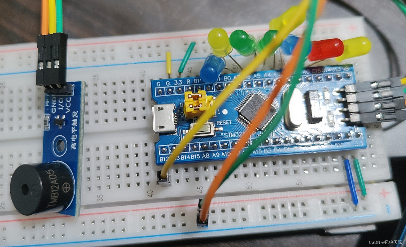
蜂鸣器选择有源高电平触发蜂鸣器。
GND——GND
VCC——正极
I/O——B12
注意:32上的PA15、PB3、和PB4是默认调试端口,如果使用需要进行额外配置,一般避开这三个端口。
二、代码部分
将3-2文件夹复制粘贴一份,重命名为“3-3 蜂鸣器”
打开之后,我们只需要将“GPIOA”改为“GPIOB”,“GPIO_Pin_0”改为“GPIO_Pin_12”即可。
#include "stm32f10x.h"                  // Device header
#include "Delay.h"

int main(void)
{
	RCC_APB2PeriphClockCmd(RCC_APB2Periph_GPIOB,ENABLE);

	GPIO_InitTypeDef GPIO_InitStructure;
	GPIO_InitStructure.GPIO_Mode = GPIO_Mode_Out_PP;
	GPIO_InitStructure.GPIO_Pin = GPIO_Pin_12;
	GPIO_InitStructure.GPIO_Speed = GPIO_Speed_50MHz;
	GPIO_Init(GPIOB,&GPIO_InitStructure);

	while(1)
	{
		GPIO_ResetBits(GPIOB,GPIO_Pin_12);
		Delay_ms(500);
		GPIO_SetBits(GPIOB,GPIO_Pin_12);
		Delay_ms(500);
	}
}
编译运行成功后即可听到蜂鸣器在响。
我们也可以让它换一个响的方式:
#include "stm32f10x.h"                  // Device header
#include "Delay.h"

int main(void)
{
	RCC_APB2PeriphClockCmd(RCC_APB2Periph_GPIOB,ENABLE);

	GPIO_InitTypeDef GPIO_InitStructure;
	GPIO_InitStructure.GPIO_Mode = GPIO_Mode_Out_PP;
	GPIO_InitStructure.GPIO_Pin = GPIO_Pin_12;
	GPIO_InitStructure.GPIO_Speed = GPIO_Speed_50MHz;
	GPIO_Init(GPIOB,&GPIO_InitStructure);

	while(1)
	{
		GPIO_ResetBits(GPIOB,GPIO_Pin_12);
		Delay_ms(100);
		GPIO_SetBits(GPIOB,GPIO_Pin_12);
		Delay_ms(100);
		GPIO_ResetBits(GPIOB,GPIO_Pin_12);
		Delay_ms(100);
		GPIO_SetBits(GPIOB,GPIO_Pin_12);
		Delay_ms(700);

	}
}
三、查看库函数的方法
- 打开.h文件翻到最下面寻找函数声明,再转到定义即可查看
- STM32用户手册
- STM32帮助手册
- 上网查询

