配置要求
如组网图所示,R3为服务器,R1为客户端,客户端与服务器
之间路由可达。其中R1和R2间互联物理接口地址分别为
10.1.2.1/24和10.1.2.2/24,R2和R3间互联物理接口地址分别
为10.1.3.2/24和10.1.3.1/24。另外,R1上创建两个逻辑接口
LoopBack 0和LoopBack 1分别模拟两个客户端用户,地址分
别为10.1.1.1/24和10.1.4.1/24。
其中一个用户(R1的LoopBack 1接口)需要远程管理设备R3,
可以在服务器端配置Telnet,用户通过密码登录,并配置基
于ACL的安全策略,保证只有符合安全策略的用户才能登录
设备。
R1配置
interface GigabitEthernet0/0/0
 ip address 10.1.2.1 255.255.255.0

interface LoopBack0
 ip address 10.1.1.1 255.255.255.0

interface LoopBack1
 ip address 10.1.4.1 255.255.255.0

ospf 1
 area 0.0.0.0
  network 10.1.1.1 0.0.0.0
  network 10.1.2.1 0.0.0.0
  network 10.1.4.1 0.0.0.0
R2配置
interface GigabitEthernet0/0/0
 ip address 10.1.2.2 255.255.255.0

interface GigabitEthernet0/0/1
 ip address 10.1.3.2 255.255.255.0

ospf 1
 area 0.0.0.0
  network 10.1.2.2 0.0.0.0
  network 10.1.3.2 0.0.0.0
R3配置
acl number 3000
 rule 5 permit tcp source 10.1.4.1 0 destination 10.1.3.1 0 destination-port eq
telnet
 rule 10 deny tcp

interface GigabitEthernet0/0/0
 ip address 10.1.3.1 255.255.255.0

ospf 1
 area 0.0.0.0
  network 10.1.3.1 0.0.0.0

user-interface vty 0 4
 acl 3000 inbound
 authentication-mode password
 user privilege level 3
 set authentication password cipher Huawei@123
架构图 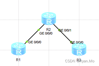
测试结果图 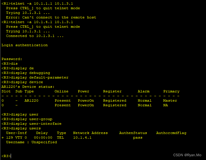
方法二
在R2上设置规则
R1配置不变
R2配置更改如下
acl number 3001
rule 5 permit tcp source 10.1.4.1 0 destination 10.1.3.1 0 destination-port eq
telnet
rule 10 deny tcp


interface GigabitEthernet0/0/0
 ip address 10.1.2.2 255.255.255.0
 traffic-filter inbound acl 3001

interface GigabitEthernet0/0/1
 ip address 10.1.3.2 255.255.255.0


ospf 1
 area 0.0.0.0
  network 10.1.2.2 0.0.0.0
  network 10.1.3.2 0.0.0.0
R3配置
interface GigabitEthernet0/0/0
 ip address 10.1.3.1 255.255.255.0

ospf 1
 area 0.0.0.0
  network 10.1.3.1 0.0.0.0

user-interface vty 0 4
 authentication-mode password
 user privilege level 3
 set authentication password cipher Huawei@123




![C语言通过MSXML6.0读写XML文件(同时支持char[]和wchar_t[]字符数组)](https://img-blog.csdnimg.cn/direct/893ce3d2bdd74cccaa1bb3911ea7b416.png)
