一,摄像头简介
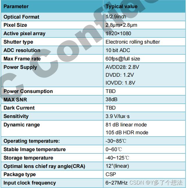
GC2093是一个高质量的1080P CMOS图像传感器,用于安全相机产品、数码相机产品和手机相机应用程序。包含了一个1920H x 1080V像素阵列、片上10位ADC和图像信号处理器。高性能和低功耗功能的全面集成使GC2093最适合设计,减少了实现过程,并延长了运动相机、汽车DVR和各种移动应用的电池寿命。它提供了RAW10和RAW8数据格式。它有一个主机常用的双线串行接口来控制整个传感器的运行。
技术规格:
二,驱动文件配置
1.源程序
~/RK3568_Android11/kernel/drivers/media/i2c/gc2093.c
2.修改i2c目录下的 Makefile以及Kconfig
kernel/drivers/media/i2c/Makefile中添加:
obj-$(CONFIG_VIDEO_GC2093)  += gc2093.o

------------------------------------------------------------------------
kernel/drivers/media/i2c/Kconfig中添加:
config VIDEO_GC2093
    tristate "GalaxyCore GC2093 sensor support"
    depends on I2C && VIDEO_V4L2 && VIDEO_V4L2_SUBDEV_API
    depends on MEDIA_CAMERA_SUPPORT
    select V4L2_FWNODE
    help
      Support for the GalaxyCore GC2093 sensor.
      To compile this driver as a module, choose M here: the
      module will be called gc2093.
3.内核中加载驱动
kernel/arch/arm64/configs/rockchip_defconfig中添加:
CONFIG_VIDEO_GC2093=y
三,DTS配置
1.摄像头链接示意图
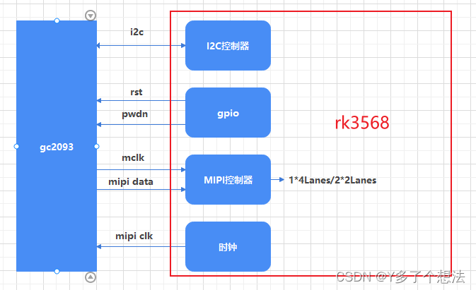
GC系列摄像头与SOC连接的主要的引脚有: i2c、rst、pwdn、mclk、MIPI Clk、MIPI DATA。
2. 硬件原理图
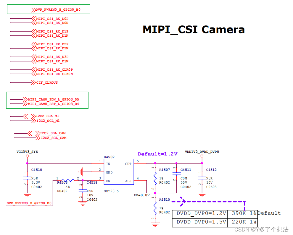
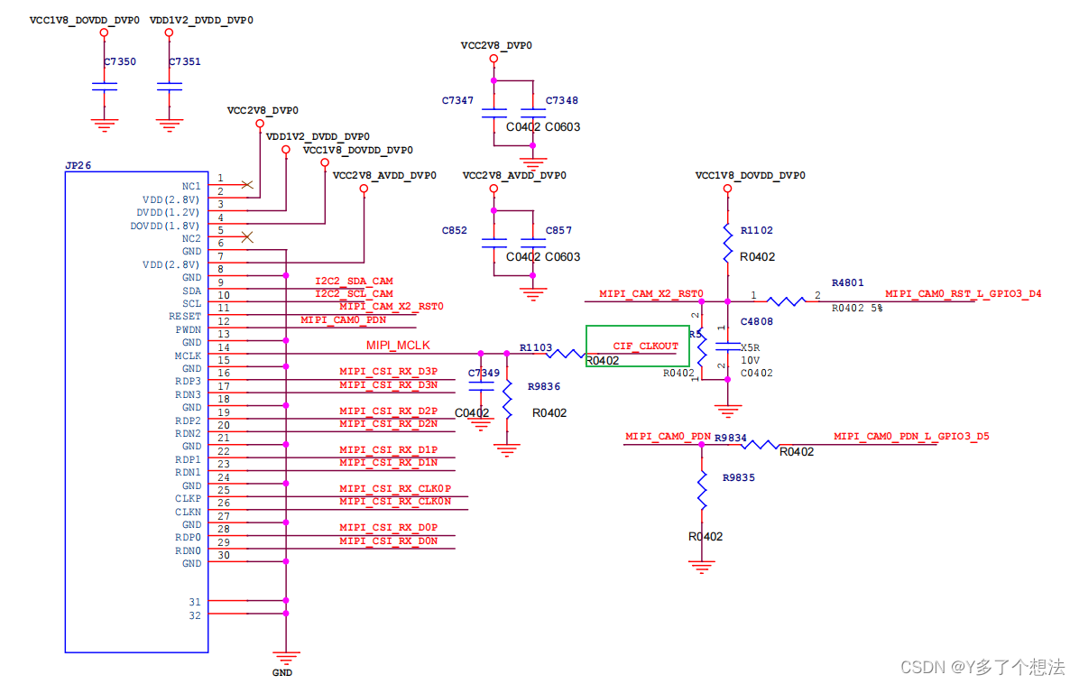
从电路图可看出关键引脚关系:
reset信号:GPIO3 D4
power down信号:GPIO3 D5
电源信号:GPIO0 B0
clock:cif_clk
3.dts节点
对于RK3568平台而言,仅有一个标准物理mipi csi2 dphy,可以工作在两个模式:full mode 和split mode,拆分为csi2_dphy0/csi2_dphy1/csi2_dphy2三个逻辑dphy,特性如下:
Full mode:
- 仅使用csi2_dphy0,csi2_dphy0与csi2_dphy1/csi2_dphy2互斥,不可同时使用;
- data lane最大4 lanes;
- 最大速率2.5Gbps/lane;
Split mode:
- 仅使用csi2_dphy1和csi2_dphy2, 与csi2_dphy0互斥,不可同时使用;
- csi2_dphy1和csi2_dphy2可同时使用;
- csi2_dphy1和csi2_dphy2各自的data lane最大是2 lanes;
- csi2_dphy1对应物理dphy的lane0/lane1;
- csi2_dphy2对应物理dphy的lane2/lane3;
- 最大速率2.5Gbps/lane
//mipi camera
&i2c2 {
    gc2093: gc2093@37 {
        compatible = "galaxycore,gc2093";
        reg = <0x37>;
        status = "okay";

        clocks = <&cru CLK_CIF_OUT>;
                clock-names = "xvclk";
                power-domains = <&power RK3568_PD_VI>;
                pinctrl-names = "default";
                pinctrl-0 = <&cif_clk>;
                avdd-supply = <&vcc_camera>; //power电源脚,需要默认拉高
                reset-gpios = <&gpio3 RK_PD4 GPIO_ACTIVE_LOW>;
                pwdn-gpios = <&gpio3 RK_PD5 GPIO_ACTIVE_HIGH>;

        rockchip,grf = <&grf>;
        rockchip,camera-module-index = <0>;
        rockchip,camera-module-facing = "front"; //模组朝向,有"back"和"front"
        rockchip,camera-module-name = "YT-RV1109-2-V1";
        rockchip,camera-module-lens-name = "40IR-2MP-F20"; //module与lens命令要与设备/etc/iqfiles中对应sensor的json文件名后面相同
        port {
            gc2093_out: endpoint {
                remote-endpoint = <&dphy0_in>;
                data-lanes = <1 2 3 4>;
            };
        };
    };
};

&csi2_dphy_hw {
    status = "okay";
};

&csi2_dphy0 {
    status = "okay";

    ports {
        #address-cells = <1>;
        #size-cells = <0>;
        port@0 {
            reg = <0>;
            #address-cells = <1>;
            #size-cells = <0>;


            dphy0_in: endpoint@1 {
                reg = <1>;
                remote-endpoint = <&gc2093_out>;
                data-lanes = <1 2 3 4>;
            };
        };

        port@1 {
            reg = <1>;
            #address-cells = <1>;
            #size-cells = <0>;


            dphy0_out: endpoint@1 {
                reg = <0>;
                remote-endpoint = <&isp0_in>;
            };
        };
    };
};

&rkisp {
    status = "okay";
};

&rkisp_mmu {
    status = "okay";
};

&rkisp_vir0 {
    status = "okay";
    port {
        #address-cells = <1>;
        #size-cells = <0>;

        isp0_in: endpoint@0 {
        reg = <0>;
        remote-endpoint = <&dphy0_out>;
        };
    };
};

&cif_clk {
    rockchip,pins =
    /* cif_clkout */
    <4 RK_PC0 1 &pcfg_pull_none>;
};


==================================================================================
vcc_camera: vcc-camera-regulator {
        compatible = "regulator-fixed";
        gpio = <&gpio0 RK_PB0 GPIO_ACTIVE_HIGH>;
        pinctrl-names = "default";
        pinctrl-0 = <&camera_pwr>;
        regulator-name = "vcc_camera";
        enable-active-high;
        regulator-always-on;
        regulator-boot-on;
    };

&pinctrl {
    cam {
        camera_pwr: camera-pwr {
            rockchip,pins =
                /* camera power en */
                <0 RK_PB0 RK_FUNC_GPIO &pcfg_pull_none>;
        };
    };
};
四,调试
1.开机log打印
rk3568:/ # dmesg | grep gc
[    0.000000] Linux version 4.19.232 (fy@001) (gcc version 6.3.1 20170404 (Linaro GCC 6.3-2017.05), GNU ld (Linaro_Binutils-2017.05) 2.27.0.20161019) #19
7 SMP PREEMPT Mon Dec 11 11:20:47 CST 2023
[    6.409370] gc2093 2-007e: driver version: 00.01.03
[    6.409504] gc2093 2-007e: 2-007e supply dovdd not found, using dummy regulator
[    6.409555] gc2093 2-007e: Linked as a consumer to regulator.0
[    6.409599] gc2093 2-007e: Linked as a consumer to regulator.13
[    6.409622] gc2093 2-007e: 2-007e supply dvdd not found, using dummy regulator
[    6.431373] gc2093 2-007e: Detected GC2093 sensor
[    6.431422] rockchip-csi2-dphy csi2-dphy0: dphy0 matches m00_f_gc2093 2-007e:bus type 4
[   51.782028] gc2093 2-007e: gc2093_s_stream: on: 1, 1920x1080@30
[  109.871508] gc2093 2-007e: gc2093_s_stream: on: 0, 1920x1080@30
[  109.905541] gc2093 2-007e: gc2093_s_stream: on: 0, sleep(33333us)
日志可以看到已经成功读到sensor id = GC2093。
2. 查看gpio的使用情况
rk3568:/ # cat /sys/kernel/debug/gpio
gpiochip0: GPIOs 0-31, parent: platform/fdd60000.gpio, gpio0:
gpio-5   (                    |usb-port0-power-ctl ) out lo
gpio-6   (                    |usb-port1-power-ctl ) out hi
gpio-8   (                    |vcc_camera          ) out hi
gpio-15  (                    |breath-led          ) out hi
gpio-16  (                    |work                ) out lo
gpio-21  (                    |enable              ) out hi
gpio-29  (                    |reset               ) out hi

gpiochip1: GPIOs 32-63, parent: platform/fe740000.gpio, gpio1:

gpiochip2: GPIOs 64-95, parent: platform/fe750000.gpio, gpio2:
gpio-73  (                    |reset               ) out hi
gpio-77  (                    |bt_default_rts      ) in  hi
gpio-79  (                    |bt_default_reset    ) out lo
gpio-80  (                    |bt_default_wake_host) in  hi
gpio-81  (                    |bt_default_wake     ) in  lo
gpio-88  (                    |io1                 ) out lo
gpio-89  (                    |io2                 ) out lo
gpio-90  (                    |io3                 ) out hi
gpio-91  (                    |io4                 ) out hi
gpio-93  (                    |usb-port2-power-ctl ) out hi
gpio-94  (                    |usb-port3-power-ctl ) out hi

gpiochip3: GPIOs 96-127, parent: platform/fe760000.gpio, gpio3:
gpio-104 (                    |mdio-reset          ) out hi
gpio-109 (                    |rs485-ctrl          ) out lo
gpio-114 (                    |headset_gpio        ) in  lo
gpio-115 (                    |spk-ctl             ) out hi
gpio-118 (                    |enable              ) out hi
gpio-119 (                    |enable              ) out lo
gpio-122 (                    |red-led             ) out hi
gpio-123 (                    |blue-led            ) out lo
gpio-124 (                    |reset               ) out lo
gpio-125 (                    |pwdn                ) out lo
可以看出vcc_camera,reset和pwdn 都是有状态,证明摄像头是加载成功了的。
3. 内核会为摄像头在目录/sys/class/video4linux下分配设备信息描述文件
rk3568:/ # grep "" /sys/class/video4linux/v*/name | grep mainpath
/sys/class/video4linux/video0/name:rkisp_mainpath
4.显示摄像头参数
rk3568:/ # v4l2-ctl -d /dev/video0 -l
User Controls

            exposure 0x00980911 (int)    : min=1 max=1121 step=1 default=1120 value=338
            horizontal_flip 0x00980914 (bool)   : default=0 value=0
            vertical_flip 0x00980915 (bool)   : default=0 value=0

Image Source Controls

            vertical_blanking 0x009e0901 (int)    : min=45 max=15303 step=1 default=45 value=45
            horizontal_blanking 0x009e0902 (int)    : min=280 max=280 step=1 default=280 value=280 flags=read-only
            analogue_gain 0x009e0903 (int)    : min=64 max=8192 step=1 default=64 value=111

Image Processing Controls

            link_frequency 0x009f0901 (intmenu): min=0 max=1 default=0 value=0
            pixel_rate 0x009f0902 (int64)  : min=0 max=316800000 step=1 default=237600000 value=237600000 flags=read-only
输出将包括不同类别的控制参数,如“User Controls”和“Image Processing Controls”。
每个控制参数通常包含以下信息:
- 控制名称:如 horizontal_flip 或 test_pattern。
- 参数类型:如 (bool) 表示布尔类型,(menu) 表示有固定选项的菜单。
- 控制标识符:如 0x00980914,这是内部用于识别控制的唯一标识。 取值范围:例如 min=0 max=1 表示取值范围从0到1。
- 默认值:如 default=0 表示控制的默认设置。 当前值:如 value=0 表示当前设置的值。
5.修改摄像头时钟频率(mclk)以及帧率(fps)
1>. gc2093.c文件中打开MCLK_27M宏定义,时钟频率为27M;注释掉则默认为24M。
2>. 帧率对应关系:
30fps:0x04,0xe2
25fps:0x05,0xdc
20fps:0x07,0x53
diff --git a/kernel/drivers/media/i2c/gc2093.c b/kernel/drivers/media/i2c/gc2093.c
index 032c6cbb53..cdc57cf1d5 100644
--- a/kernel/drivers/media/i2c/gc2093.c
+++ b/kernel/drivers/media/i2c/gc2093.c
@@ -42,7 +42,7 @@
 #define MIPI_FREQ_396M         396000000

 /* 27M or 24M */
-//#define MCLK_27M
+#define MCLK_27M

 #ifdef MCLK_27M
 #define GC2093_XVCLK_FREQ      27000000
@@ -501,8 +501,8 @@ static const struct reg_sequence gc2093_1080p_hdr_settings[] = {
        {0x0010, 0x8c},
        {0x0013, 0x15},
        {0x0019, 0x0c},
-       {0x0041, 0x04}, //30fps: 0x4e2;   25FPS: 0x5dc:  20FPS: 0x753
-       {0x0042, 0xe2},
+       {0x0041, 0x05}, //30fps: 0x4e2;   25FPS: 0x5dc:  20FPS: 0x753
+       {0x0042, 0xdc},
        {0x0053, 0x60},
        {0x008d, 0x92},
        {0x0090, 0x00},
五,遇到的问题
1.摄像头加载失败,读不到sensor id
[6.874014] gc2093 2-007e: driver version: 00.01.03
[6.874127] gc2093 2-007e: Failed to get reset-gpios
[6.874201] gc2093 2-007e: 2-007e supply dovdd not found, using dummy regulator
[6.874270] gc2093 2-007e: Linked as a consumer to regulator.0
[6.874311] gc2093 2-007e: 2-007e supply avdd not found, using dummy regulator
[6.874408] gc2093 2-007e: 2-007e supply dvdd not found, using dummy regulator
[6.895219] gc2093 2-007e: i2c read failed at addr: 3f0
[6.895444] gc2093 2-007e: i2c read failed at addr: 3f1
[6.895471] gc2093 2-007e: Failed to read sensor id, (-6)
要确保reset和pwdn引脚没有被复用,且初始状态正确。
2. 显示异常拉伸
具体现象:系统横屏状态(0度,180度)下预览画面有拉伸;竖屏状态(90度,270度)下预览画面就是正常。
hardware/rockchip/camera/etc/camera/camera3_profiles_rk356x.xml
安卓配置文件中 xml中有模组方式配置,找到gc2093摄像头配置,修改sensor.orientation值(0,90,180,270)
<sensor.orientation value="0"/>
实测修改后显示正常。
