IPSec&GRE
- 手工方式建立IPSec隧道组网
- 实验拓扑
- 配置步骤
- 第一步配置IP地址
- 第二步配置静态路由
- 第三步配置IPSec
- 抓包测试
- GRE Over IPSec功能的配置组网
- 实验拓扑
- 配置命令
- 配置GRE使用静态路由组网图
- 实验拓扑
- 配置步骤
- 1.配置RouterA
- 2.配置RouterB
- 3.配置RouterC
- 4.验证配置结果
手工方式建立IPSec隧道组网
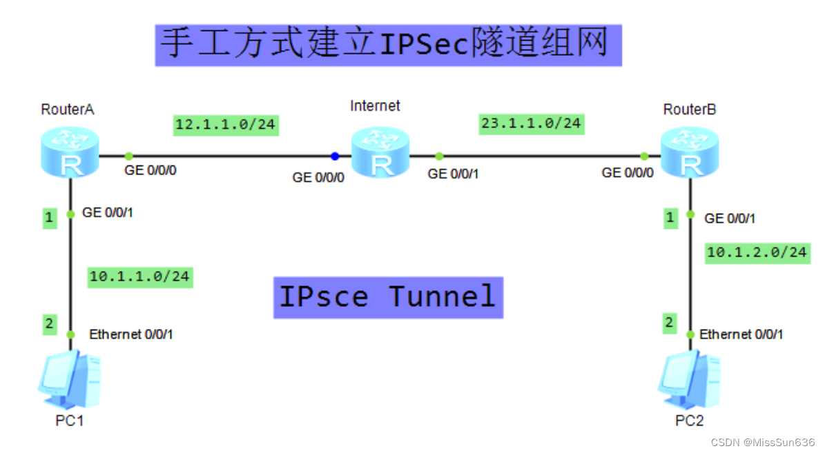
实验拓扑
配置步骤
第一步配置IP地址
RouterA
sysname RouterA
#
interface GigabitEthernet0/0/0
 ip address 12.1.1.1 255.255.255.0
 ipsec policy map1
#
interface GigabitEthernet0/0/1
 ip address 10.1.1.1 255.255.255.0
Internet
sysname Internet
#
interface GigabitEthernet0/0/0
 ip address 12.1.1.2 255.255.255.0
#
interface GigabitEthernet0/0/1
 ip address 23.1.1.2 255.255.255.0
RouterB
sysname RouterB
#
interface GigabitEthernet0/0/0
 ip address 23.1.1.3 255.255.255.0
#
interface GigabitEthernet0/0/1
 ip address 10.1.2.1 255.255.255.0
第二步配置静态路由
RouterA
ip route-static 10.1.2.0 255.255.255.0 12.1.1.2   //配置一条目的地址是总部内网的静态路由
ip route-static 23.1.1.0 255.255.255.0 12.1.1.2  //配置一条目的地址是总部外网出口的静态路由
RouterB
ip route-static 10.1.1.0 255.255.255.0 23.1.1.2  //配置一条目的地址是分支内网的静态路由
ip route-static 12.1.1.0 255.255.255.0 23.1.1.2 //配置一条目的地址是分支外网出口的静态路由
第三步配置IPSec
RouterA
acl number 3101   //配置ACL 3101,匹配从分支子网到总部子网的流量
 rule 5 permit ip source 10.1.1.0 0.0.0.255 destination 10.1.2.0 0.0.0.255
#
ipsec proposal tran1  //配置IPSec安全提议
 esp authentication-algorithm sha2-256
 esp encryption-algorithm aes-128
#
ipsec policy map1 10 manual   //配置手动方式安全策略
 security acl 3101
 proposal tran1
 tunnel local 12.1.1.1
 tunnel remote 23.1.1.3
 sa spi inbound esp 54321
 sa string-key inbound esp cipher wml
 sa spi outbound esp 12345
 sa string-key outbound esp cipher wml
#
interface GigabitEthernet0/0/0
 ipsec policy map1
RouterB
acl number 3101   //配置ACL 3101,匹配从总部子网到分支子网的流量
 rule 5 permit ip source 10.1.2.0 0.0.0.255 destination 10.1.1.0 0.0.0.255
#
ipsec proposal tran1  //配置IPSec安全提议
 esp authentication-algorithm sha2-256
 esp encryption-algorithm aes-128
#
ipsec policy use1 10 manual  //配置手动方式安全策略
 security acl 3101
 proposal tran1
 tunnel local 23.1.1.3
 tunnel remote 12.1.1.1
 sa spi inbound esp 12345
 sa string-key inbound esp cipher wml
 sa spi outbound esp 54321
 sa string-key outbound esp cipher wml
#
interface GigabitEthernet0/0/0
 ipsec policy use1
- 在Router上执行命令display ike sa,可以看到SA建立成功。
抓包测试


GRE Over IPSec功能的配置组网
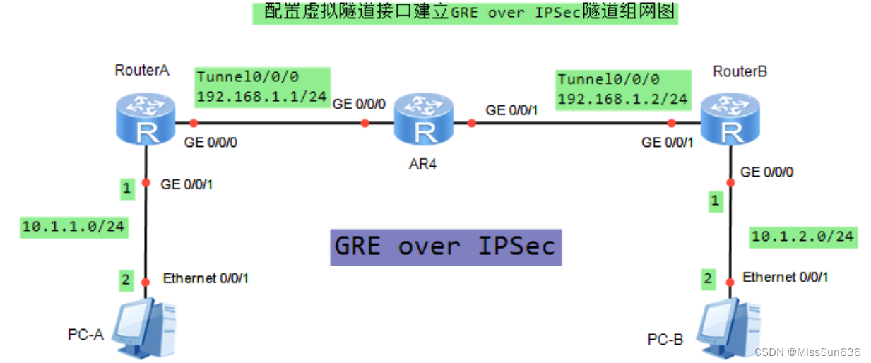
实验拓扑
配置命令
RouterA
sysname RouterA
//在RouterA上配置IPSec安全提议。
ipsec proposal tran1
 esp authentication-algorithm sha2-256
 esp encryption-algorith#m aes-128
//在RouterA上配置IKE安全提议
ike proposal 5
 encryption-algorithm aes-cbc-128
 dh group14
//在RouterA上配置IKE对等体。
ike peer spub v1
 pre-shared-key cipher wml
 ike-proposal 5
//在RouterA上配置安全框架。
ipsec profile profile1
 ike-peer spub
 proposal tran1
#
interface GigabitEthernet0/0/0
 ip address 14.1.1.1 255.255.255.0
#
interface GigabitEthernet0/0/1
 ip address 10.1.1.1 255.255.255.0
#
interface Tunnel0/0/0
 ip address 192.168.1.1 255.255.255.0
 tunnel-protocol gre
 source 14.1.1.1
 destination 24.1.1.2
 ipsec profile profile1 //在RouterA的接口上引用安全框架。
#
ip route-static 10.1.2.0 255.255.255.0 Tunnel0/0/0
ip route-static 24.1.1.0 255.255.255.0 14.1.1.4
RouterB
sysname RouterB
#
ipsec proposal tran1
 esp authentication-algorithm sha2-256
 esp encryption-algorithm aes-128
#
ike proposal 5
 encryption-algorithm aes-cbc-128
 dh group14
#
ike peer spua v1
 pre-shared-key cipher wml
 ike-proposal 5
#
ipsec profile profile1
 ike-peer spua
 proposal tran1
#
interface GigabitEthernet0/0/0
 ip address 10.1.2.1 255.255.255.0
#
interface GigabitEthernet0/0/1
 ip address 24.1.1.2 255.255.255.0
#
interface Tunnel0/0/0
 ip address 192.168.1.2 255.255.255.0
 tunnel-protocol gre
 source 24.1.1.2
 destination 14.1.1.1
 ipsec profile profile1
#
ip route-static 10.1.1.0 255.255.255.0 Tunnel0/0/0
ip route-static 14.1.1.0 255.255.255.0 24.1.1.4
R4
//只需要正常配置两个接口得IP地址即可
interface GigabitEthernet0/0/0
 ip address 14.1.1.4 255.255.255.0
#
interface GigabitEthernet0/0/1
 ip address 24.1.1.4 255.255.255.0
配置GRE使用静态路由组网图
实验拓扑
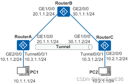
配置步骤
1.配置RouterA
sysname RouterA
#
interface GigabitEthernet1/0/0  //配置公网出接口
 ip address 20.1.1.1 255.255.255.0
#
interface GigabitEthernet2/0/0  //配置私网出接口
 ip address 10.1.1.2 255.255.255.0
#
interface Tunnel0/0/1  //配置Tunnel接口,Tunnel的源地址是发出报文的实际接口IP地址,目的地址是接收报文的实际接口IP地址
 ip address 10.3.1.1 255.255.255.0
 tunnel-protocol gre
 source 20.1.1.1
 destination 30.1.1.2
#
ospf 1  //配置公网路由
 area 0.0.0.0
  network 20.1.1.0 0.0.0.255
#
ip route-static 10.2.1.0 255.255.255.0 Tunnel0/0/1  //配置私网静态路由,下一条接口为Tunnel接口
2.配置RouterB
sysname RouterB
#
interface GigabitEthernet1/0/0
ip address 20.1.1.2 255.255.255.0
#
interface GigabitEthernet2/0/0
ip address 30.1.1.1 255.255.255.0
#
ospf 1  //配置公网路由
 area 0.0.0.0
  network 20.1.1.0 0.0.0.255
  network 30.1.1.0 0.0.0.255
3.配置RouterC
sysname RouterC
#
interface GigabitEthernet1/0/0  //配置公网出接口
ip address 30.1.1.2 255.255.255.0
#
interface GigabitEthernet2/0/0  //配置私网出接口
 ip address 10.2.1.2 255.255.255.0
#
interface Tunnel0/0/1  //配置Tunnel接口,Tunnel的源地址是发出报文的实际接口IP地址,目的地址是接收报文的实际接口IP地址
 ip address 10.3.1.2 255.255.255.0
 tunnel-protocol gre
 source 30.1.1.2
 destination 20.1.1.1
#
ospf 1  //配置公网路由
 area 0.0.0.0
  network 30.1.1.0 0.0.0.255
#
ip route-static 10.1.1.0 255.255.255.0 Tunnel0/0/1  //配置私网静态路由,下一条接口为Tunnel接口
4.验证配置结果
- 在RouterA和RouterC上执行display ip routing-table命令,可以看到去往对端目的地址的出接口为Tunnel接口。
- PC1和PC2能互相Ping通。


