前言
本章使用fbtft添加spi lcd st7735/gc9306。
fbtft生成fb0设备,后续通过lvgl可以实现自定义界面绘制。
代码参考
https://gitee.com/openLuat/LuatOS/blob/master/components/lcd/luat_lcd_gc9306x.c
硬件是合宙的,合宙esp32有支持,仿照他们配置reg就行。
https://blog.csdn.net/m0_72868108/article/details/127702912
https://blog.csdn.net/zhoubingda/article/details/107993689
https://elixir.bootlin.com/linux/latest/source/include/video/mipi_display.h#L96
一、电路图
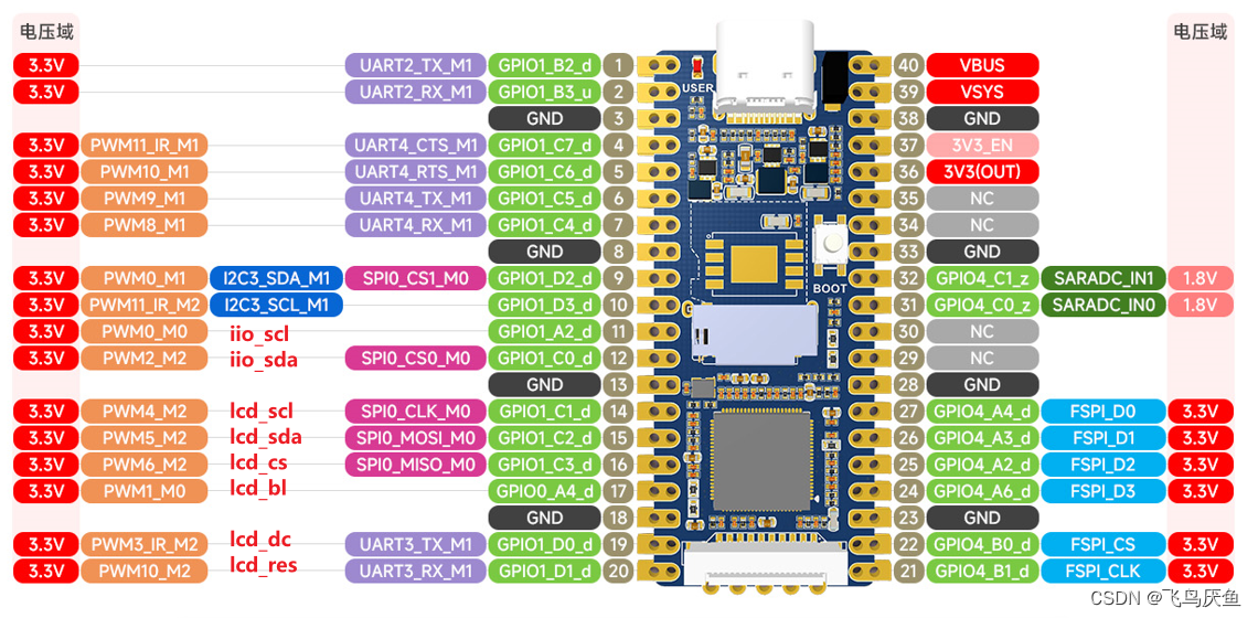
使用开发板的spi0的scl以及mosi,其余的复用引脚实现,把lcd分配在一起。
二、dtsi
luckfox-pico-main\sysdrv\source\kernel\arch\arm\boot\dts\rv1103g-luckfox-pico.dts
注意先将之前的spi0注销掉。
最前面的配置普通gpio比较简单,仿照hx711实现的即可,注意结合自己的io引脚实现。
spi0定义的spi0m0_pins中默认是打开了miso的,但是由于我这个spi屏幕不需要输入,所以直接复用了。
部分参数的意义加了注释,方便理解。
/**********spi**********/
/{
	/*LCD_CS -- USE MISO*/
    gpio1pc3:gpio1pc3 {
        compatible = "regulator-fixed";
        pinctrl-names = "default";
        pinctrl-0 = <&gpio1_pc3>;
        regulator-name = "gpio1_pc3";
        regulator-always-on;
    };

	/*LCD_BL*/
	gpio0pa4:gpio0pa4 {
		compatible = "regulator-fixed";
		pinctrl-names = "default";
		pinctrl-0 = <&gpio0_pa4>;
		regulator-name = "gpio0_pa4";
		regulator-always-on;
	};

	/*LCD_DC*/
    gpio1pd0:gpio1pd0 {
        compatible = "regulator-fixed";
        pinctrl-names = "default";
        pinctrl-0 = <&gpio1_pd0>;
        regulator-name = "gpio1_pd0";
        regulator-always-on;
    };

	/*LCD_RES*/
    gpio1pd1:gpio1pd1 {
        compatible = "regulator-fixed";
        pinctrl-names = "default";
        pinctrl-0 = <&gpio1_pd1>;
        regulator-name = "gpio1_pd1";
        regulator-always-on;
    };
};

&pinctrl {
	/*LCD_CS -- USE MISO*/
    gpio1-pc3 {
        gpio1_pc3:gpio1-pc3 {
            rockchip,pins = <1 RK_PC3 RK_FUNC_GPIO &pcfg_pull_none>;
        };
    };

	/*LCD_BL*/
	gpio0-pa4 {
		gpio0_pa4:gpio0-pa4 {
			rockchip,pins =	<0 RK_PA4 RK_FUNC_GPIO &pcfg_pull_none>;
		};
	};

	/*LCD_DC*/
    gpio1-pd0 {
        gpio1_pd0:gpio1-pd0 {
            rockchip,pins = <1 RK_PD0 RK_FUNC_GPIO &pcfg_pull_none>;
        };
    };

	/*LCD_RES*/
    gpio1-pd1 {
        gpio1_pd1:gpio1-pd1 {
            rockchip,pins = <1 RK_PD1 RK_FUNC_GPIO &pcfg_pull_none>;
        };
    };

    spi0 {
        /omit-if-no-ref/
        spi0m0_pins: spi0m0-pins {
            rockchip,pins =
                /* spi0_clk_m0 */
                <1 RK_PC1 4 &pcfg_pull_none>,
                /* spie_miso_m0 */
                /* <1 RK_PC3 6 &pcfg_pull_none>, */	// 先不动,还用uart4作为bl
                /* spi_mosi_m0 */
                <1 RK_PC2 6 &pcfg_pull_none>;
        };
    };
};

&spi0 {
	status = "okay";
	pinctrl-names = "default";
	pinctrl-0 = <&spi0m0_pins>;		// 包含clk,mi,mo
	// cs-gpios = <&gpio1 RK_PC0 1>;// 片选,也可以用spi0m0_cs0代替,需要确认pinctrl中是否定义了,1表示高电平有效
	// cs-gpios = <&gpio1 26 1>;	// 26=gpio1C2=3(C)*8+2
	#address-cells = <1>;			// 挂载设备的描述位,比如两个设备就是0,1,设1,若四个则是00-10,设2
	#size-cells = <0>;				// 默认不可改
	/*
	spidev@0 {						// 模拟出spi0设备,0对应的spi下挂载的设备号,和reg一致
		compatible = "rockchip,spidev";
		spi-max-frequency = <1000000000>;
		reg = <0>;
	};
	*/

	lcd: lcd@0{						// 若添加第二个lcd,这里选1
		status = "okay";
		compatible = "sitronix,st7735"; //"sitronix,gc9306"	//后续验证另一个lcd直接改名
		reg = <0>;					// 若添加第二个lcd,对应选1

		spi-max-frequency = <6000000>;	// 24M	由于我的逻辑分析仪最高只能24Mhz,所以设置6Mhz,其实可以设为48M
		spi-cpol;
		spi-cpha;
		rotate = <0>;				// 旋转角度,lcd驱动里会读取并设置对应寄存器
		fps = <30>;
		rgb;
		buswidth = <8>;

		cs = <&gpio1 RK_PC3 GPIO_ACTIVE_LOW>;		//spi0_miso
		led = <&gpio0 RK_PA4 GPIO_ACTIVE_LOW>;		//BL
		dc = <&gpio1 RK_PD0 GPIO_ACTIVE_HIGH>;		//DC
		reset = <&gpio1 RK_PD1 GPIO_ACTIVE_LOW>;	//RES

		debug = <0x7>;
	};
};
三、makefile——添加驱动
# luckfox-pico\sysdrv\source\kernel\drivers\staging\fbtft\Makefile
obj-$(CONFIG_FB_TFT_GC9306)     += fb_gc9306.o
obj-$(CONFIG_FB_TFT_ST7735)     += fb_st7735.o

# luckfox-pico\sysdrv\source\kernel\drivers\staging\Makefile
obj-$(CONFIG_FB_TFT)		+= fbtft/
四、Kconfig——定义驱动
# luckfox-pico\sysdrv\source\kernel\drivers\staging\fbtft\Kconfig
config FB_TFT_GC9306
	tristate "FB driver for the GC9306 LCD Controller"
	depends on FB_TFT
	help
	  Generic Framebuffer support for GC9306

config FB_TFT_ST7735
	tristate "FB driver for the GC9306 LCD Controller"
	depends on FB_TFT
	help
	  Generic Framebuffer support for ST7735
五、deconfig——编译驱动
luckfox-pico\sysdrv\source\kernel\arch\arm\configs\luckfox_rv1106_linux_defconfig
# spi lcd -- st7735s
CONFIG_SPI_MASTER=y
CONFIG_SPI_DESIGNWARE=y
CONFIG_SPI_DW_MMIO=y
CONFIG_FB=y
CONFIG_FB_TFT=y
CONFIG_FB_TFT_ST7735=y
CONFIG_FB_TFT_GC9306=y
六、更改fbtft驱动
由于内核版本变更,可能有写接口不适用。
对比milkv比较好添加驱动,而luckfox的改动又不同。
主要是fbtft-core.c的改动
- 添加头文件,用于获取dtsi中引脚的高低有效电平配置
- 更改fbtft_request_one_gpio
- 更改fbtft_reset,添加cs引脚设置
- 改变led-gpio为led
luckfox-pico\sysdrv\source\kernel\drivers\staging\fbtft\fbtft-core.c
#include <linux/gpio.h> //add
#include <linux/of_gpio.h> //add


static int fbtft_request_one_gpio(struct fbtft_par *par,
                  const char *name, int index,
                  struct gpio_desc **gpiop)
{
    struct device *dev = par->info->device;
    struct device_node *node = dev->of_node;
    int gpio, flags, ret = 0;
    enum of_gpio_flags of_flags;
    if (of_find_property(node, name, NULL)) {
        gpio = of_get_named_gpio_flags(node, name, index, &of_flags);
        if (gpio == -ENOENT)
            return 0;
        if (gpio == -EPROBE_DEFER)
            return gpio;
        if (gpio < 0) {
            dev_err(dev,
                "failed to get '%s' from DT\n", name);
            return gpio;
        }
         //active low translates to initially low
        flags = (of_flags & OF_GPIO_ACTIVE_LOW) ? GPIOF_OUT_INIT_LOW :
                            GPIOF_OUT_INIT_HIGH;
        ret = devm_gpio_request_one(dev, gpio, flags,
                        dev->driver->name);
        if (ret) {
            dev_err(dev,
                "gpio_request_one('%s'=%d) failed with %d\n",
                name, gpio, ret);
            return ret;
        }

        *gpiop = gpio_to_desc(gpio);
        fbtft_par_dbg(DEBUG_REQUEST_GPIOS, par, "%s: '%s' = GPIO%d\n",
                            __func__, name, gpio);
    }

    return ret;
}


static void fbtft_reset(struct fbtft_par *par)
{
	if (!par->gpio.reset)
		return;

	fbtft_par_dbg(DEBUG_RESET, par, "%s()\n", __func__);

	gpiod_set_value_cansleep(par->gpio.reset, 1);
	usleep_range(20, 40);
	gpiod_set_value_cansleep(par->gpio.reset, 0);
	msleep(120);
	gpiod_set_value_cansleep(par->gpio.reset, 1);
	msleep(120);

	gpiod_set_value_cansleep(par->gpio.cs, 0);  /* Activate chip */
	msleep(120);
}


// 这里也可以设置led-gpios,但是你fbtft_request_gpios中也要相应改变。
static struct fbtft_platform_data *fbtft_properties_read(struct device *dev)
{
	struct fbtft_platform_data *pdata;

	if (!dev_fwnode(dev)) {
		dev_err(dev, "Missing platform data or properties\n");
		return ERR_PTR(-EINVAL);
	}

	pdata = devm_kzalloc(dev, sizeof(*pdata), GFP_KERNEL);
	if (!pdata)
		return ERR_PTR(-ENOMEM);

	pdata->display.width = fbtft_property_value(dev, "width");
	pdata->display.height = fbtft_property_value(dev, "height");
	pdata->display.regwidth = fbtft_property_value(dev, "regwidth");
	pdata->display.buswidth = fbtft_property_value(dev, "buswidth");
	pdata->display.backlight = fbtft_property_value(dev, "backlight");
	pdata->display.bpp = fbtft_property_value(dev, "bpp");
	pdata->display.debug = fbtft_property_value(dev, "debug");
	pdata->rotate = fbtft_property_value(dev, "rotate");
	pdata->bgr = device_property_read_bool(dev, "bgr");
	pdata->fps = fbtft_property_value(dev, "fps");
	pdata->txbuflen = fbtft_property_value(dev, "txbuflen");
	pdata->startbyte = fbtft_property_value(dev, "startbyte");
	device_property_read_string(dev, "gamma", (const char **)&pdata->gamma);

	if (device_property_present(dev, "led"))
		pdata->display.backlight = 1;
	if (device_property_present(dev, "init"))
		pdata->display.fbtftops.init_display =
			fbtft_init_display_from_property;

	pdata->display.fbtftops.request_gpios = fbtft_request_gpios;

	return pdata;
}
七、git diff
总结git改动,后面是新增的文件。
diff --git a/sysdrv/source/kernel/arch/arm/boot/dts/rv1103g-luckfox-pico.dts b/sysdrv/source/kernel/arch/arm/boot/dts/rv1103g-luckfox-pico.dts
index 0f1a686fc..fd4f767a5 100644
--- a/sysdrv/source/kernel/arch/arm/boot/dts/rv1103g-luckfox-pico.dts
+++ b/sysdrv/source/kernel/arch/arm/boot/dts/rv1103g-luckfox-pico.dts
@@ -143,33 +143,18 @@ &i2c3 {
 	clock-frequency = <100000>;
 };

-// /**********SPI**********/
-&spi0 {
-	status = "okay";
-	pinctrl-names = "default";
-	pinctrl-0 = <&spi0m0_pins>;
-	cs-gpios = <&gpio1 RK_PC0 1>;
-	// cs-gpios = <&gpio1 26 1>;
-	#address-cells = <1>;
-	#size-cells = <0>;
-	spidev@0 {
-		compatible = "rockchip,spidev";
-		spi-max-frequency = <1000000000>;
-		reg = <0>;
-	};
-};

 // /**********UART**********/
-&uart3 {
-	status = "okay";
-	pinctrl-names = "default";
-	pinctrl-0 = <&uart3m1_xfer>;
-};
-&uart4 {
-	status = "okay";
-	pinctrl-names = "default";
-	pinctrl-0 = <&uart4m1_xfer>;
-};
+// &uart3 {
+// 	status = "okay";
+// 	pinctrl-names = "default";
+// 	pinctrl-0 = <&uart3m1_xfer>;
+// };
+// &uart4 {
+// 	status = "okay";
+// 	pinctrl-names = "default";
+// 	pinctrl-0 = <&uart4m1_xfer>;
+// };
 // &uart5 {
 // 	status = "okay";
 // 	pinctrl-names = "default";
@@ -178,18 +163,18 @@ &uart4 {

 /**********PWM**********/

-&pwm0 {
-	status = "okay";
-	pinctrl-names = "active";
-	pinctrl-0 = <&pwm0m0_pins>;
-	// pinctrl-0 = <&pwm0m1_pins>;
-};
-&pwm1 {
-	status = "okay";
-	pinctrl-names = "active";
-	pinctrl-0 = <&pwm1m0_pins>;
-	// pinctrl-0 = <&pwm1m1_pins>;
-};
+// &pwm0 {
+// 	status = "okay";
+// 	pinctrl-names = "active";
+// 	pinctrl-0 = <&pwm0m0_pins>;
+// 	// pinctrl-0 = <&pwm0m1_pins>;
+// };
+// &pwm1 {
+// 	status = "okay";
+// 	pinctrl-names = "active";
+// 	pinctrl-0 = <&pwm1m0_pins>;
+// 	// pinctrl-0 = <&pwm1m1_pins>;
+// };

 // &pwm2 {
 // 	status = "okay";
@@ -234,21 +219,187 @@ &pwm1 {
 // 	pinctrl-0 = <&pwm9m0_pins>;
 // };

-&pwm10 {
-	status = "okay";
-	pinctrl-names = "active";
-	pinctrl-0 = <&pwm10m1_pins>;
-	// pinctrl-0 = <&pwm10m2_pins>;
-	// pinctrl-0 = <&pwm10m0_pins>;
+// &pwm10 {
+// 	status = "okay";
+// 	pinctrl-names = "active";
+// 	pinctrl-0 = <&pwm10m1_pins>;
+// 	// pinctrl-0 = <&pwm10m2_pins>;
+// 	// pinctrl-0 = <&pwm10m0_pins>;
+// };
+// &pwm11 {
+// 	status = "okay";
+// 	pinctrl-names = "active";
+// 	pinctrl-0 = <&pwm11m1_pins>;
+// 	// pinctrl-0 = <&pwm11m2_pins>;
+// 	// pinctrl-0 = <&pwm11m0_pins>;
+// };
+
+
+
+/**********iio**********/
+/{
+    /* hx711 clk */
+    gpio1pa2:gpio1pa2 {
+        compatible = "regulator-fixed";
+        pinctrl-names = "default";
+        pinctrl-0 = <&gpio1_pa2>;
+        regulator-name = "gpio1_pa2";
+        regulator-always-on;
+    };
+
+    /* hx711 sda */
+    gpio1pc0:gpio1pc0 {
+        compatible = "regulator-fixed";
+        pinctrl-names = "default";
+        pinctrl-0 = <&gpio1_pc0>;
+        regulator-name = "gpio1_pc0";
+        regulator-always-on;
+    };
 };
-&pwm11 {
-	status = "okay";
-	pinctrl-names = "active";
-	pinctrl-0 = <&pwm11m1_pins>;
-	// pinctrl-0 = <&pwm11m2_pins>;
-	// pinctrl-0 = <&pwm11m0_pins>;
+
+&pinctrl {
+    /* hx711 clk */
+    gpio1-pa2 {
+        gpio1_pa2:gpio1-pa2 {
+            rockchip,pins = <1 RK_PA2 RK_FUNC_GPIO &pcfg_pull_none>;
+        };
+    };
+
+    /* hx711 sda */
+    gpio1-pc0 {
+        gpio1_pc0:gpio1-pc0 {
+            rockchip,pins = <1 RK_PC0 RK_FUNC_GPIO &pcfg_pull_none>;
+        };
+    };
+};
+
+/ {
+    hx711:hx711 {
+        status = "okay";
+        compatible = "avia,hx711";
+        sck-gpios = <&gpio1 RK_PA2 GPIO_ACTIVE_HIGH>;    /* clk */
+        dout-gpios = <&gpio1 RK_PC0 GPIO_ACTIVE_HIGH>;   /* sda */
+        avdd-supply = <&vcc_3v3>;//vcc3v3_sys
+        clock-frequency = <400000>;
+    };
 };

+/**********spi**********/
+/{
+	/*LCD_CS -- USE MISO*/
+    gpio1pc3:gpio1pc3 {
+        compatible = "regulator-fixed";
+        pinctrl-names = "default";
+        pinctrl-0 = <&gpio1_pc3>;
+        regulator-name = "gpio1_pc3";
+        regulator-always-on;
+    };
+
+	/*LCD_BL*/
+	gpio0pa4:gpio0pa4 {
+		compatible = "regulator-fixed";
+		pinctrl-names = "default";
+		pinctrl-0 = <&gpio0_pa4>;
+		regulator-name = "gpio0_pa4";
+		regulator-always-on;
+	};
+
+	/*LCD_DC*/
+    gpio1pd0:gpio1pd0 {
+        compatible = "regulator-fixed";
+        pinctrl-names = "default";
+        pinctrl-0 = <&gpio1_pd0>;
+        regulator-name = "gpio1_pd0";
+        regulator-always-on;
+    };
+
+	/*LCD_RES*/
+    gpio1pd1:gpio1pd1 {
+        compatible = "regulator-fixed";
+        pinctrl-names = "default";
+        pinctrl-0 = <&gpio1_pd1>;
+        regulator-name = "gpio1_pd1";
+        regulator-always-on;
+    };
+};

+&pinctrl {
+	/*LCD_CS -- USE MISO*/
+    gpio1-pc3 {
+        gpio1_pc3:gpio1-pc3 {
+            rockchip,pins = <1 RK_PC3 RK_FUNC_GPIO &pcfg_pull_none>;
+        };
+    };
+
+	/*LCD_BL*/
+	gpio0-pa4 {
+		gpio0_pa4:gpio0-pa4 {
+			rockchip,pins =	<0 RK_PA4 RK_FUNC_GPIO &pcfg_pull_none>;
+		};
+	};

+	/*LCD_DC*/
+    gpio1-pd0 {
+        gpio1_pd0:gpio1-pd0 {
+            rockchip,pins = <1 RK_PD0 RK_FUNC_GPIO &pcfg_pull_none>;
+        };
+    };
+
+	/*LCD_RES*/
+    gpio1-pd1 {
+        gpio1_pd1:gpio1-pd1 {
+            rockchip,pins = <1 RK_PD1 RK_FUNC_GPIO &pcfg_pull_none>;
+        };
+    };
+
+    spi0 {
+        /omit-if-no-ref/
+        spi0m0_pins: spi0m0-pins {
+            rockchip,pins =
+                /* spi0_clk_m0 */
+                <1 RK_PC1 4 &pcfg_pull_none>,
+                /* spie_miso_m0 */
+                /* <1 RK_PC3 6 &pcfg_pull_none>, */	// 先不动,还用uart4作为bl
+                /* spi_mosi_m0 */
+                <1 RK_PC2 6 &pcfg_pull_none>;
+        };
+    };
+};

+&spi0 {
+	status = "okay";
+	pinctrl-names = "default";
+	pinctrl-0 = <&spi0m0_pins>;		// 包含clk,mi,mo
+	// cs-gpios = <&gpio1 RK_PC0 1>;// 片选,也可以用spi0m0_cs0代替,需要确认pinctrl中是否定义了,1表示高电平有效
+	// cs-gpios = <&gpio1 26 1>;	// 26=gpio1C2=3(C)*8+2
+	#address-cells = <1>;			// 挂载设备的描述位,比如两个设备就是0,1,设1,若四个则是00-10,设2
+	#size-cells = <0>;				// 默认不可改
+	/*
+	spidev@0 {						// 模拟出spi0设备,0对应的spi下挂载的设备号,和reg一致
+		compatible = "rockchip,spidev";
+		spi-max-frequency = <1000000000>;
+		reg = <0>;
+	};
+	*/
+
+	lcd: lcd@0{						// 若添加第二个lcd,这里选1
+		status = "okay";
+		compatible = "sitronix,st7735"; //"sitronix,gc9306"	//后续验证另一个lcd直接改名
+		reg = <0>;					// 若添加第二个lcd,对应选1
+
+		spi-max-frequency = <6000000>;	// 24M	由于我的逻辑分析仪最高只能24Mhz,所以设置6Mhz,其实可以设为48M
+		spi-cpol;
+		spi-cpha;
+		rotate = <0>;				// 旋转角度,lcd驱动里会读取并设置对应寄存器
+		fps = <30>;
+		rgb;
+		buswidth = <8>;
+
+		cs = <&gpio1 RK_PC3 GPIO_ACTIVE_LOW>;		//spi0_miso
+		led = <&gpio0 RK_PA4 GPIO_ACTIVE_LOW>; 		//BL
+		dc = <&gpio1 RK_PD0 GPIO_ACTIVE_HIGH>;		//DC
+		reset = <&gpio1 RK_PD1 GPIO_ACTIVE_LOW>;	//RES
+
+		debug = <0x7>;
+	};
+};
diff --git a/sysdrv/source/kernel/arch/arm/configs/luckfox_rv1106_linux_defconfig b/sysdrv/source/kernel/arch/arm/configs/luckfox_rv1106_linux_defconfig
index 4c54b6965..17fc90225 100755
--- a/sysdrv/source/kernel/arch/arm/configs/luckfox_rv1106_linux_defconfig
+++ b/sysdrv/source/kernel/arch/arm/configs/luckfox_rv1106_linux_defconfig
@@ -320,3 +320,20 @@ CONFIG_DEBUG_FS=y
 # CONFIG_SCHED_DEBUG is not set
 # CONFIG_FTRACE is not set
 # CONFIG_RUNTIME_TESTING_MENU is not set
+
+# sensor -- hx711
+CONFIG_HX711=y
+CONFIG_IIO=y
+
+# spi lcd -- st7735s
+CONFIG_SPI_MASTER=y
+CONFIG_SPI_DESIGNWARE=y
+CONFIG_SPI_DW_MMIO=y
+CONFIG_FB=y
+CONFIG_FB_TFT=y
+CONFIG_FB_TFT_ST7735=y
+CONFIG_FB_TFT_GC9306=y
+# CONFIG_FB_BACKLIGHT=y
+
+# lvgl
+# CONFIG_LVGL=y
diff --git a/sysdrv/source/kernel/drivers/staging/fbtft/Kconfig b/sysdrv/source/kernel/drivers/staging/fbtft/Kconfig
index dad1ddcd7..f77fb81a7 100644
--- a/sysdrv/source/kernel/drivers/staging/fbtft/Kconfig
+++ b/sysdrv/source/kernel/drivers/staging/fbtft/Kconfig
@@ -206,3 +206,15 @@ config FB_TFT_WATTEROTT
 	depends on FB_TFT
 	help
 	  Generic Framebuffer support for WATTEROTT
+
+config FB_TFT_GC9306
+	tristate "FB driver for the GC9306 LCD Controller"
+	depends on FB_TFT
+	help
+	  Generic Framebuffer support for GC9306
+
+config FB_TFT_ST7735
+	tristate "FB driver for the GC9306 LCD Controller"
+	depends on FB_TFT
+	help
+	  Generic Framebuffer support for ST7735
diff --git a/sysdrv/source/kernel/drivers/staging/fbtft/Makefile b/sysdrv/source/kernel/drivers/staging/fbtft/Makefile
index e87193f7d..27bfe4e3a 100644
--- a/sysdrv/source/kernel/drivers/staging/fbtft/Makefile
+++ b/sysdrv/source/kernel/drivers/staging/fbtft/Makefile
@@ -37,3 +37,6 @@ obj-$(CONFIG_FB_TFT_UC1611)      += fb_uc1611.o
 obj-$(CONFIG_FB_TFT_UC1701)      += fb_uc1701.o
 obj-$(CONFIG_FB_TFT_UPD161704)   += fb_upd161704.o
 obj-$(CONFIG_FB_TFT_WATTEROTT)   += fb_watterott.o
+
+obj-$(CONFIG_FB_TFT_GC9306)     += fb_gc9306.o
+obj-$(CONFIG_FB_TFT_ST7735)     += fb_st7735.o
diff --git a/sysdrv/source/kernel/drivers/staging/fbtft/fbtft-core.c b/sysdrv/source/kernel/drivers/staging/fbtft/fbtft-core.c
index d0c8d85f3..a58fbd31f 100644
--- a/sysdrv/source/kernel/drivers/staging/fbtft/fbtft-core.c
+++ b/sysdrv/source/kernel/drivers/staging/fbtft/fbtft-core.c
@@ -30,6 +30,9 @@
 #include "fbtft.h"
 #include "internal.h"

+#include <linux/gpio.h> //add
+#include <linux/of_gpio.h> //add
+
 static unsigned long debug;
 module_param(debug, ulong, 0000);
 MODULE_PARM_DESC(debug, "override device debug level");
@@ -71,20 +74,42 @@ void fbtft_dbg_hex(const struct device *dev, int groupsize,
 EXPORT_SYMBOL(fbtft_dbg_hex);

 static int fbtft_request_one_gpio(struct fbtft_par *par,
-				  const char *name, int index,
-				  struct gpio_desc **gpiop)
+                  const char *name, int index,
+                  struct gpio_desc **gpiop)
 {
-	struct device *dev = par->info->device;
-
-	*gpiop = devm_gpiod_get_index_optional(dev, name, index,
-					       GPIOD_OUT_LOW);
-	if (IS_ERR(*gpiop))
-		return dev_err_probe(dev, PTR_ERR(*gpiop), "Failed to request %s GPIO\n", name);
-
-	fbtft_par_dbg(DEBUG_REQUEST_GPIOS, par, "%s: '%s' GPIO\n",
-		      __func__, name);
-
-	return 0;
+    struct device *dev = par->info->device;
+    struct device_node *node = dev->of_node;
+    int gpio, flags, ret = 0;
+    enum of_gpio_flags of_flags;
+    if (of_find_property(node, name, NULL)) {
+        gpio = of_get_named_gpio_flags(node, name, index, &of_flags);
+        if (gpio == -ENOENT)
+            return 0;
+        if (gpio == -EPROBE_DEFER)
+            return gpio;
+        if (gpio < 0) {
+            dev_err(dev,
+                "failed to get '%s' from DT\n", name);
+            return gpio;
+        }
+         //active low translates to initially low
+        flags = (of_flags & OF_GPIO_ACTIVE_LOW) ? GPIOF_OUT_INIT_LOW :
+                            GPIOF_OUT_INIT_HIGH;
+        ret = devm_gpio_request_one(dev, gpio, flags,
+                        dev->driver->name);
+        if (ret) {
+            dev_err(dev,
+                "gpio_request_one('%s'=%d) failed with %d\n",
+                name, gpio, ret);
+            return ret;
+        }
+
+        *gpiop = gpio_to_desc(gpio);
+        fbtft_par_dbg(DEBUG_REQUEST_GPIOS, par, "%s: '%s' = GPIO%d\n",
+                            __func__, name, gpio);
+    }
+
+    return ret;
 }

 static int fbtft_request_gpios(struct fbtft_par *par)
@@ -223,8 +248,11 @@ static void fbtft_reset(struct fbtft_par *par)
 	usleep_range(20, 40);
 	gpiod_set_value_cansleep(par->gpio.reset, 0);
 	msleep(120);
+	gpiod_set_value_cansleep(par->gpio.reset, 1);
+	msleep(120);

-	gpiod_set_value_cansleep(par->gpio.cs, 1);  /* Activate chip */
+	gpiod_set_value_cansleep(par->gpio.cs, 0);  /* Activate chip */
+	msleep(120);
 }

 static void fbtft_update_display(struct fbtft_par *par, unsigned int start_line,
@@ -1171,7 +1199,7 @@ static struct fbtft_platform_data *fbtft_properties_read(struct device *dev)
 	pdata->startbyte = fbtft_property_value(dev, "startbyte");
 	device_property_read_string(dev, "gamma", (const char **)&pdata->gamma);

-	if (device_property_present(dev, "led-gpios"))
+	if (device_property_present(dev, "led"))
 		pdata->display.backlight = 1;
 	if (device_property_present(dev, "init"))
 		pdata->display.fbtftops.init_display =
八、驱动
luckfox-pico\sysdrv\source\kernel\drivers\staging\fbtft\fb_st7735.c
这是依据st7789v改编的,具体驱动如何改动可以参考我的文章,后续会补全。
【fbtft】如何添加fbtft驱动
8.1 st7735
// SPDX-License-Identifier: GPL-2.0+
/*
 * FB driver for the ST7735 LCD Controller
 *
 * Copyright (C) 2015 Dennis Menschel
 */

#include <linux/bitops.h>
#include <linux/delay.h>
#include <linux/init.h>
#include <linux/kernel.h>
#include <linux/module.h>
#include <video/mipi_display.h>

#include "fbtft.h"

#define DRVNAME "fb_st7735"

#define DEFAULT_GAMMA \
	"70 2C 2E 15 10 09 48 33 53 0B 19 18 20 25\n" \
	"70 2C 2E 15 10 09 48 33 53 0B 19 18 20 25"

#define HSD20_IPS_GAMMA \
	"D0 05 0A 09 08 05 2E 44 45 0F 17 16 2B 33\n" \
	"D0 05 0A 09 08 05 2E 43 45 0F 16 16 2B 33"

#define HSD20_IPS 1

/**
 * enum st7735_command - ST7735 display controller commands
 *
 * @PORCTRL: porch setting
 * @GCTRL: gate control
 * @VCOMS: VCOM setting
 * @VDVVRHEN: VDV and VRH command enable
 * @VRHS: VRH set
 * @VDVS: VDV set
 * @VCMOFSET: VCOM offset set
 * @PWCTRL1: power control 1
 * @PVGAMCTRL: positive voltage gamma control
 * @NVGAMCTRL: negative voltage gamma control
 *
 * The command names are the same as those found in the datasheet to ease
 * looking up their semantics and usage.
 *
 * Note that the ST7735 display controller offers quite a few more commands
 * which have been omitted from this list as they are not used at the moment.
 * Furthermore, commands that are compliant with the MIPI DCS have been left
 * out as well to avoid duplicate entries.
 */
enum st7735_command {
	PORCTRL = 0xB2,
	GCTRL = 0xB7,
	VCOMS = 0xBB,
	VDVVRHEN = 0xC2,
	VRHS = 0xC3,
	VDVS = 0xC4,
	VCMOFSET = 0xC5,
	PWCTRL1 = 0xD0,
	PVGAMCTRL = 0xE0,
	NVGAMCTRL = 0xE1,
};

#define MADCTL_BGR BIT(3) /* bitmask for RGB/BGR order */
#define MADCTL_MV BIT(5) /* bitmask for page/column order */
#define MADCTL_MX BIT(6) /* bitmask for column address order */
#define MADCTL_MY BIT(7) /* bitmask for page address order */

/**
 * init_display() - initialize the display controller
 *
 * @par: FBTFT parameter object
 *
 * Most of the commands in this init function set their parameters to the
 * same default values which are already in place after the display has been
 * powered up. (The main exception to this rule is the pixel format which
 * would default to 18 instead of 16 bit per pixel.)
 * Nonetheless, this sequence can be used as a template for concrete
 * displays which usually need some adjustments.
 *
 * Return: 0 on success, < 0 if error occurred.
 */
static int init_display(struct fbtft_par *par)
{
	par->fbtftops.reset(par);//硬复位

	write_reg(par,0x01);//软复位
	mdelay(150);

	write_reg(par,0x11);//软复位
	mdelay(500);

	//ST7735s Frame Rate
	write_reg(par,0xB1,0x05,0x3c,0x3c);

	write_reg(par,0xB2,0x05,0x3c,0x3c);

	write_reg(par,0xB3,0x05,0x3c,0x3c,0x05,0x3c,0x3c);

	write_reg(par,0xB4,0x03); //Column inversion

	//ST7735s Power Sequence
	write_reg(par,0xC0,0x28,0x08,0x04);

	write_reg(par,0xC1,0xc0);

	write_reg(par,0xC2,0x0d,0x00);

	write_reg(par,0xC3,0x8d,0x2a); //VCOM

	write_reg(par,0xc4,0x8d,0xee); //MX, MY, RGB mode
	write_reg(par,0xc5,0x1a);
	write_reg(par,0x36,0xc0);

	//ST7735s Gamma Sequence
	write_reg(par,0xe0,0x04,0x22,0x07,0x0a,0x2e,0x30,0x25,0x2a,0x28,0x26,0x2e,0x3a,0x00,0x01,0x03,0x13);

	write_reg(par,0xe1,0x04,0x16,0x06,0x0d,0x2d,0x26,0x23,0x27,0x27,0x25,0x2d,0x3b,0x00,0x01,0x04,0x13);

	write_reg(par,0x3A,0x05); // 65k mode

	// write_reg(par,0x20);	// MIPI_DCS_EXIT_INVERT_MODE

	write_reg(par,0x29);	// Display on
	mdelay(100);

	return 0;
}

/**
 * set_var() - apply LCD properties like rotation and BGR mode
 *
 * @par: FBTFT parameter object
 *
 * Return: 0 on success, < 0 if error occurred.
 */
static int set_var(struct fbtft_par *par)
{
	u8 madctl_par = 0;

	if (par->bgr)
		madctl_par |= MADCTL_BGR;
	switch (par->info->var.rotate) {
	case 0:
		madctl_par = 0xc0;
		break;
	case 90:
		madctl_par = 0x70;
		break;
	case 180:
		madctl_par = 0x00;
		break;
	case 270:
		madctl_par = 0xA0;
		break;
	default:
		return -EINVAL;
	}
	write_reg(par, MIPI_DCS_SET_ADDRESS_MODE, madctl_par);	//0x36
	return 0;
}

/**
 * set_gamma() - set gamma curves
 *
 * @par: FBTFT parameter object
 * @curves: gamma curves
 *
 * Before the gamma curves are applied, they are preprocessed with a bitmask
 * to ensure syntactically correct input for the display controller.
 * This implies that the curves input parameter might be changed by this
 * function and that illegal gamma values are auto-corrected and not
 * reported as errors.
 *
 * Return: 0 on success, < 0 if error occurred.
 */
static int set_gamma(struct fbtft_par *par, u32 *curves)
{
	// int i;
	// int j;
	// int c; /* curve index offset */

	// /*
	//  * Bitmasks for gamma curve command parameters.
	//  * The masks are the same for both positive and negative voltage
	//  * gamma curves.
	//  */
	// static const u8 gamma_par_mask[] = {
	// 	0xFF, /* V63[3:0], V0[3:0]*/
	// 	0x3F, /* V1[5:0] */
	// 	0x3F, /* V2[5:0] */
	// 	0x1F, /* V4[4:0] */
	// 	0x1F, /* V6[4:0] */
	// 	0x3F, /* J0[1:0], V13[3:0] */
	// 	0x7F, /* V20[6:0] */
	// 	0x77, /* V36[2:0], V27[2:0] */
	// 	0x7F, /* V43[6:0] */
	// 	0x3F, /* J1[1:0], V50[3:0] */
	// 	0x1F, /* V57[4:0] */
	// 	0x1F, /* V59[4:0] */
	// 	0x3F, /* V61[5:0] */
	// 	0x3F, /* V62[5:0] */
	// };

	// for (i = 0; i < par->gamma.num_curves; i++) {
	// 	c = i * par->gamma.num_values;
	// 	// for (j = 0; j < par->gamma.num_values; j++)
	// 	// 	curves[c + j] &= gamma_par_mask[j];
	// 	write_reg(par, PVGAMCTRL + i,
	// 		  curves[c + 0],  curves[c + 1],  curves[c + 2],
	// 		  curves[c + 3],  curves[c + 4],  curves[c + 5],
	// 		  curves[c + 6],  curves[c + 7],  curves[c + 8],
	// 		  curves[c + 9],  curves[c + 10], curves[c + 11],
	// 		  curves[c + 12], curves[c + 13]);
	// }

	write_reg(par,0xe0,0x04,0x22,0x07,0x0a,0x2e,0x30,0x25,0x2a,0x28,0x26,0x2e,0x3a,0x00,0x01,0x03,0x13);

	write_reg(par,0xe1,0x04,0x16,0x06,0x0d,0x2d,0x26,0x23,0x27,0x27,0x25,0x2d,0x3b,0x00,0x01,0x04,0x13);

	return 0;
}

/**
 * blank() - blank the display
 *
 * @par: FBTFT parameter object
 * @on: whether to enable or disable blanking the display
 *
 * Return: 0 on success, < 0 if error occurred.
 */
static int blank(struct fbtft_par *par, bool on)
{
	if (on)
		write_reg(par, MIPI_DCS_SET_DISPLAY_OFF);
	else
		write_reg(par, MIPI_DCS_SET_DISPLAY_ON);
	return 0;
}

static struct fbtft_display display = {
	.regwidth = 8,
	.width = 128,//240,
	.height = 160,//320,
	.gamma_num = 2,
	.gamma_len = 14,
	.gamma = HSD20_IPS_GAMMA,
	.fbtftops = {
		.init_display = init_display,
		.set_var = set_var,
		.set_gamma = set_gamma,
		.blank = blank,
	},
};

FBTFT_REGISTER_DRIVER(DRVNAME, "sitronix,st7735", &display);

MODULE_ALIAS("spi:" DRVNAME);
MODULE_ALIAS("platform:" DRVNAME);
MODULE_ALIAS("spi:st7735");
MODULE_ALIAS("platform:st7735");

MODULE_DESCRIPTION("FB driver for the ST7735 LCD Controller");
MODULE_AUTHOR("Dennis Menschel");
MODULE_LICENSE("GPL");
8.2 gc9306
// SPDX-License-Identifier: GPL-2.0+
/*
 * FB driver for the GC9306 LCD Controller
 *
 * Copyright (C) 2015 Dennis Menschel
 */

#include <linux/bitops.h>
#include <linux/delay.h>
#include <linux/init.h>
#include <linux/kernel.h>
#include <linux/module.h>
#include <video/mipi_display.h>

#include "fbtft.h"

#define DRVNAME "fb_gc9306"

#define GC9306_IPS_GAMMA \
    "02 00 00 1b 1f 0b\n" \
    "01 03 00 28 2b 0e\n" \
    "0b 08 3b 04 03 4c\n" \
    "0e 07 46 04 05 51\n" \
    "08 15 15 1f 22 0F\n" \
    "0b 13 11 1f 21 0F"

/**
 * init_display() - initialize the display controller
 *
 * @par: FBTFT parameter object
 *
 * Most of the commands in this init function set their parameters to the
 * same default values which are already in place after the display has been
 * powered up. (The main exception to this rule is the pixel format which
 * would default to 18 instead of 16 bit per pixel.)
 * Nonetheless, this sequence can be used as a template for concrete
 * displays which usually need some adjustments.
 *
 * Return: 0 on success, < 0 if error occurred.
 */
static int init_display(struct fbtft_par *par)
{
	par->fbtftops.reset(par);//硬复位

	mdelay(50);

    //display control setting
    write_reg(par, 0xfe);
    write_reg(par, 0xef);
    write_reg(par, MIPI_DCS_SET_ADDRESS_MODE, 0x48);//MX, MY, RGB mode 刷新方向 48竖屏
    write_reg(par, MIPI_DCS_SET_PIXEL_FORMAT, MIPI_DCS_PIXEL_FMT_16BIT);//65k mode
    write_reg(par, 0xad,0x33);
    write_reg(par, 0xaf,0x55);
    write_reg(par, 0xae,0x2b);

    //GC9306 Power Sequence
    write_reg(par, 0xa4,0x44,0x44);
    write_reg(par, 0xa5,0x42,0x42);
    write_reg(par, 0xaa,0x88,0x88);
    write_reg(par, 0xae,0x2b);
    write_reg(par, 0xe8,0x11,0x0b);
    write_reg(par, 0xe3,0x01,0x10);
    write_reg(par, 0xff,0x61);
    write_reg(par, 0xac,0x00);
    write_reg(par, 0xaf,0x67);
    write_reg(par, 0xa6,0x2a,0x2a);
    write_reg(par, 0xa7,0x2b,0x2b);
    write_reg(par, 0xa8,0x18,0x18);
    write_reg(par, 0xa9,0x2a,0x2a);

    //display window 240X320 匹配mode
    write_reg(par, 0x2a,0x00,0x00,0x00,0xef);   //MIPI_DCS_SET_COLUMN_ADDRESS - 240
    write_reg(par, 0x2b,0x00,0x00,0x01,0x3f);   //MIPI_DCS_SET_PAGE_ADDRESS - 320
    write_reg(par, 0x2c);                       //MIPI_DCS_WRITE_MEMORY_START

    //GC9306 Gamma Sequence
    write_reg(par, 0xF0,0x02,0x00,0x00,0x1b,0x1f,0x0b);
    write_reg(par, 0xF1,0x01,0x03,0x00,0x28,0x2b,0x0e);
    write_reg(par, 0xF2,0x0b,0x08,0x3b,0x04,0x03,0x4c);
    write_reg(par, 0xF3,0x0e,0x07,0x46,0x04,0x05,0x51);
    write_reg(par, 0xF4,0x08,0x15,0x15,0x1f,0x22,0x0F);
    write_reg(par, 0xF5,0x0b,0x13,0x11,0x1f,0x21,0x0F);

    /* Sleep Out */
    write_reg(par, 0x11);                       //MIPI_DCS_EXIT_SLEEP_MODE
    mdelay(100);

    write_reg(par, 0x2c);                       //MIPI_DCS_WRITE_MEMORY_START

    write_reg(par, 0x20);                       //MIPI_DCS_EXIT_INVERT_MODE

    // luat_lcd_clear(par, BLACK);

    /* display on */
	write_reg(par, 0x29);                       //MIPI_DCS_SET_DISPLAY_ON - 29
	mdelay(100);

    return 0;
}

/**
 * set_var() - apply LCD properties like rotation and BGR mode
 *
 * @par: FBTFT parameter object
 *
 * Return: 0 on success, < 0 if error occurred.
 */
static int set_var(struct fbtft_par *par)
{
	u8 madctl_par = 0;

	if (par->bgr)
		madctl_par =0x48;
	switch (par->info->var.rotate) {
	case 0:
		madctl_par = 0x48;
		break; //48
	case 90:
		madctl_par = 0xE8;
		break;
	case 180:
		madctl_par =0x28;
		break;
	case 270:
		madctl_par =0xF8;
		break;
	default:
		return -EINVAL;
	}
	write_reg(par, MIPI_DCS_SET_ADDRESS_MODE, madctl_par);
	return 0;
}


/**
 * set_gamma() - set gamma curves
 *
 * @par: FBTFT parameter object
 * @curves: gamma curves
 *
 * Before the gamma curves are applied, they are preprocessed with a bitmask
 * to ensure syntactically correct input for the display controller.
 * This implies that the curves input parameter might be changed by this
 * function and that illegal gamma values are auto-corrected and not
 * reported as errors.
 *
 * Return: 0 on success, < 0 if error occurred.
 */
static int set_gamma(struct fbtft_par *par, u32 *curves)
{
    //GC9306 Gamma Sequence
    write_reg(par, 0xF0,0x02,0x00,0x00,0x1b,0x1f,0x0b);
    write_reg(par, 0xF1,0x01,0x03,0x00,0x28,0x2b,0x0e);
    write_reg(par, 0xF2,0x0b,0x08,0x3b,0x04,0x03,0x4c);
    write_reg(par, 0xF3,0x0e,0x07,0x46,0x04,0x05,0x51);
    write_reg(par, 0xF4,0x08,0x15,0x15,0x1f,0x22,0x0F);
    write_reg(par, 0xF5,0x0b,0x13,0x11,0x1f,0x21,0x0F);

	return 0;
}

/**
 * blank() - blank the display
 *
 * @par: FBTFT parameter object
 * @on: whether to enable or disable blanking the display
 *
 * Return: 0 on success, < 0 if error occurred.
 */
static int blank(struct fbtft_par *par, bool on)
{
	if (on)
		write_reg(par, MIPI_DCS_SET_DISPLAY_OFF);
	else
		write_reg(par, MIPI_DCS_SET_DISPLAY_ON);
	return 0;
}

static struct fbtft_display display = {
	.regwidth = 8,
	.width = 240,
	.height = 320,
	.gamma_num = 6,
	.gamma_len = 6,
	.gamma = GC9306_IPS_GAMMA,
	.fbtftops = {
		.init_display = init_display,
		.set_var = set_var,
		.set_gamma = set_gamma,
		.blank = blank,
	},
};

FBTFT_REGISTER_DRIVER(DRVNAME, "sitronix,gc9306", &display);

MODULE_ALIAS("spi:" DRVNAME);
MODULE_ALIAS("platform:" DRVNAME);
MODULE_ALIAS("spi:gc9306");
MODULE_ALIAS("platform:gc9306");

MODULE_DESCRIPTION("FB driver for the GC9306 LCD Controller");
MODULE_AUTHOR("Dennis Menschel & Youkai");
MODULE_LICENSE("GPL");
九、验证驱动
注意:luckfox驱动成功时屏幕为黑色,但是背光是开的,不清楚是不是补色没设导致的,有了解的朋友还请多指教。
执行dmesg查看fb驱动是否正常加载了。
# dmesg | grep fb_
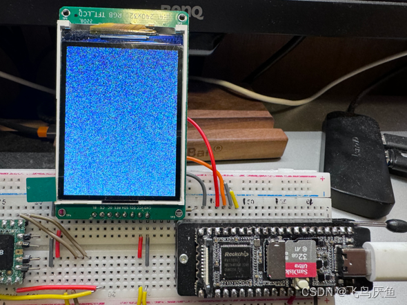
[ 0.945494] graphics fb0: fb_gc9306 frame buffer, 240x320, 150 KiB video memory, 4 KiB buffer memory, fps=30, spi0.0 at 6 MHz
// 测试花屏
# cat /dev/urandom > /dev/fb0
// 测试清屏
# cat /dev/zero > /dev/fb0
如果两个测试命令都成功了,则说明你驱动可以正常加载了。
十、小结
本章只是介绍如何添加lcd spi驱动,后续应用实现要通过lvgl完成。
有兴趣的话可以参考下【lvgl】linux开发板搭建环境,只需要改变makefile中的cc路径即可。
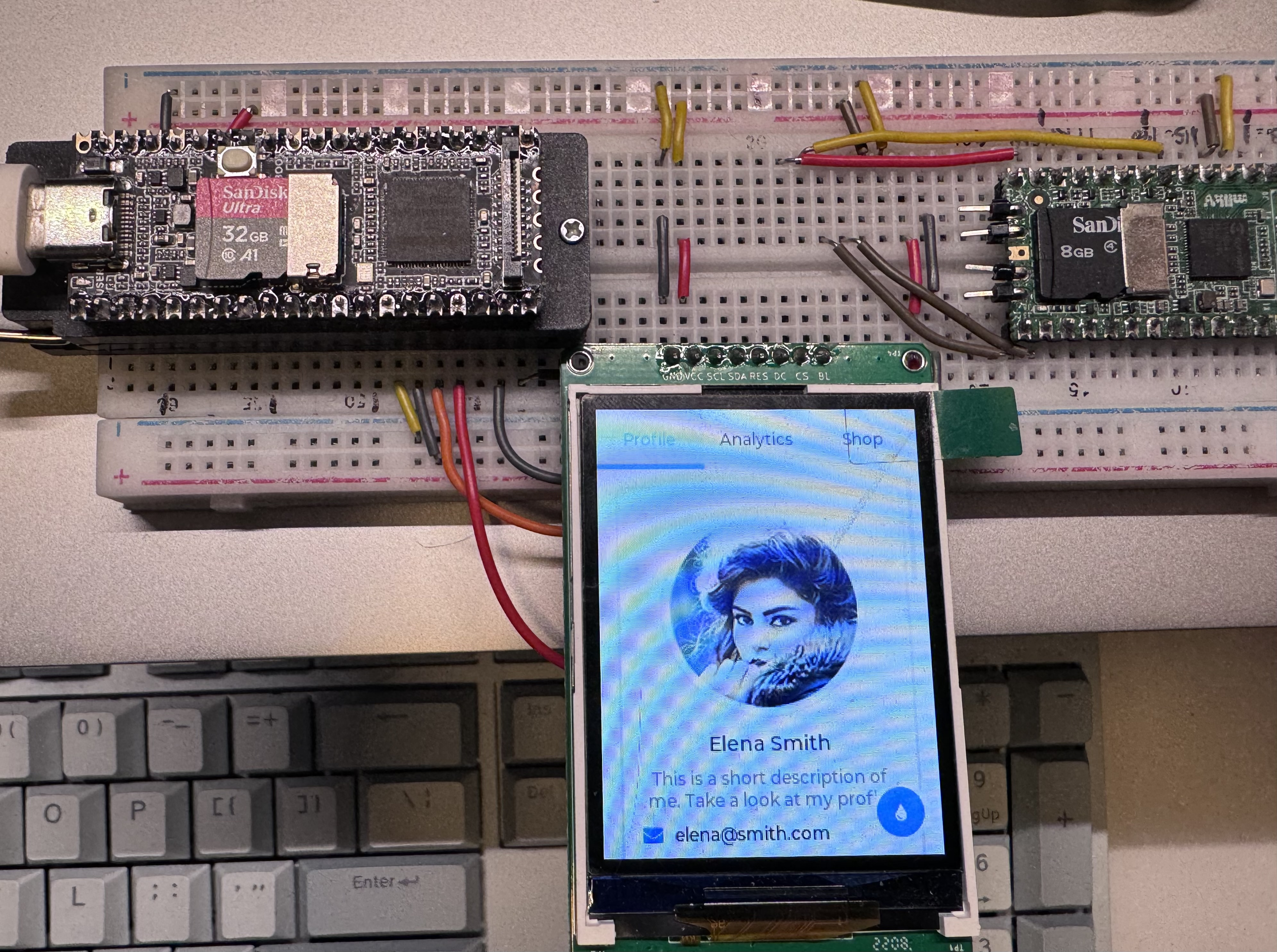
放一个lvgl示例运行的结果图。