如何使用 ESP-01S 模块
原始PDF文档
参考:
-
将 ESP-01 用作 WiFi shield的更好方法 (e-tinkers.com)
-
How do I use ESP8266 ESP-01S WiFi Module with ESP-01S Adapter - Using Arduino / Programming Questions - Arduino Forum
-
ESP-01S WiFi 模块 – 配置布线 - 技术探索 (techexplorations.com)
它是如何工作的?
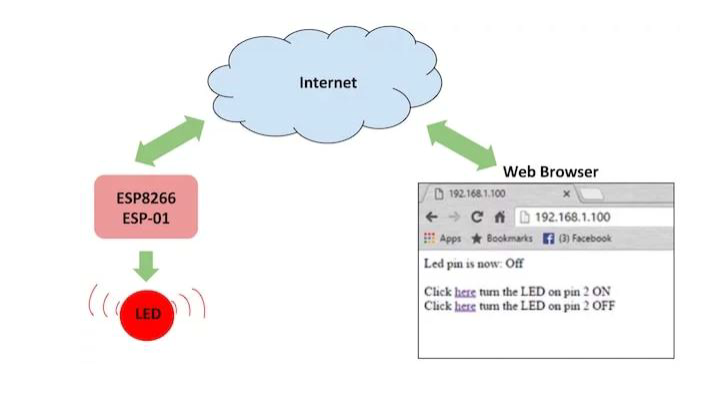
ESP8266 可以通过本地 Wi-Fi 网络或互联网(端口后)进行控制转发)。ESP-01 模块具有 GPIO 引脚,可通过互联网编程打开/关闭 LED 或继电器。该模块可通过串行引脚(RX、TX)使用 Arduino/USB 转 TTL 转换器进行编程。
将硬件连接到 ESP8266
我们可以使用 USB 到 TTL 转换器或使用 Arduino 对 ESP8266 进行编程。您可以遵循以下三种方法将代码上传到 ESP8266 — 选择最适合您的方法。请参阅每个图表的下图,并相应地设置硬件。

引脚排列成两行,每行有 4 个。有些型号在PCB上有pi n描述,这使得它变得简单。在顶行,您可以从左到右找到以下引脚:
- 接地(电源接地)
- GPIO2(数字 I/O 可编程)
- GPIO0 (数字 I/O 可编程,也用于引导模式)
- RX – UART 接收通道
在底部(第二行),您可以找到:
- TX – UART 传输通道
- CH_PD(使能/断电,必须直接或通过电阻上拉至3.3V)
- REST – 复位,必须拉至 3.3v)
- 可变电源-3.3V电源
电源和电流消耗
所有 esp8266 arduino 兼容模块必须由来自任何类型的直流电流供电,可以提供稳定的 3.3V 和至少 250mA.此外,逻辑信号的额定电压为3.3v,RX通道应由3.3V除数降压保护。将此模块与 Arduino 或其他提供 5v 的板一起使用时应小心,因为该模块通常不附带过功率保护,很容易损坏。
以下是乐鑫声明的功耗:
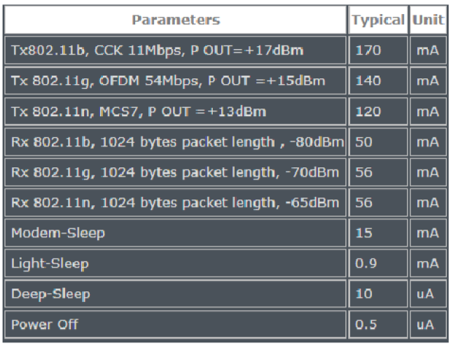
如果您打算在由电池或太阳能供电的项目中使用 ESP-01,它是必须了解有关 ESP8266 arduino 睡眠模式的所有信息。当前版本提供 3 种不同的睡眠模式,可以通过编程方式触发。ESP8266WiFi 库提供了调用睡眠模式的特定功能,这些函数可以采用设置参数,在唤醒后更改回调作业,例如在射频模块断电或打开的情况下醒来。
最重要的模式是DEEP_SLEEP,因为睡眠期间的功耗非常低。深度睡眠模式在以特定间隔进行数据记录并在测量之间空闲的项目中非常常见。
为了在使用 esp8266 arduino 兼容模块时利用此模式,ESP-01标准,您需要做一些解决方法并将 REST 引脚与 GPIO16 引脚连接(在默认的 6 个六针中不可用)。
这是一个示例
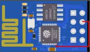
完成此连接后,您可以使用以下命令触发深度睡眠模式:
与 ESP-01 对话 (AT / LUA / Arduino)
ESP8266-01 为您提供了多种通过 RX/TX 引脚或空中 (OTA) 与其通信的方法。区别不仅在于硬件,还在于开箱即用的固件类型。无论默认安装什么固件,您都应该能够按照数据表中的固件刷新说明刷新首选固件。该模块可以使用LUA代码,Arduino代码或直接通过AT命令进行编程,这使我们在项目中嵌入此设备时具有更大的自由度。另外,很少有python固件模式,但我还没有机会测试它们。我个人选择与Arduino合作是因为过去的经验和可用库的音调。开箱即用,该模块已准备好通过 AT 命令进行通信,无需任何其他额外的设置或配置。有许多软件应用程序可用于通过AT进行通信,并具有现成的工具和功能的音调,这将使一切变得更容易。我使用了ESPlorer,我完全推荐它,你可以在这里找到它。启动后,为了能够使用 AT 命令,模块应在串行监视器上显示“就绪”。
几个基本的 AT 命令示例:
AT – 响应正常

AT+CWLAP – 列出附近可用的 WiFi 网络

AT+GMR – 检查固件版本

AT+CWJAP=“ ”,“” – 使用凭据加入 WiFi 网络

AT+CIFSR – 获取当前分配的 IP 地址
为了能够与 ESP8266 arduino 兼容模块通信,您需要选择一种将其与计算机连接的方式。您可以通过标准串行与模块通信
通过使用Arduino板作为代理/网桥进行通信RS232
Arduino Uno 与之前的所有主板的不同之处在于它不使用 FTDI USB 转串行驱动程序芯片。相反,它具有编程为USB到串行转换器的Atmega16U2(Atmega8U2至版本R2)。为了使用Arduino作为桥接器,首先您需要在其上加载一个空程序。完成此操作后,您需要建立以下连接才能工作:
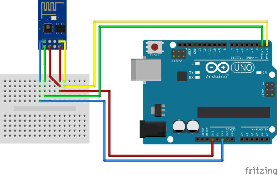
注意图中接地引脚
| UNO | ESP-01S |
|---|---|
| RX | RX |
| TX | TX |
| 3.3V | 3.3V |
| GND | GND |
| RST | RST |
| CH_PD OR EN | 3.3V |
之后,您应该能够通过选择Arduino的COM端口,设置适当的波特率,在串行监视器中查看数据并发送AT命令,默认值应为115200,并进行其他设置以读取“NL和CR,
当每个项目核心都需要可扩展时,每个嵌入式 DIY 或商业项目中的无线固件 (FOTA) 解决方案即使不是必需的功能,也是非常理想的功能。因此,通过Wi-Fi连接而不是串行从远程计算机上传代码的可能性在每个项目中都是一个很高的优势。首先,您需要FOTA需求先决条件。第一个固件上传需要通过串行完成,如果在程序中正确实现了 OTA 例程,则可以通过无线方式完成后续上传。
由于该模块需要无线暴露,因此存在被黑客入侵并加载恶意代码的机会。您可以通过设置自定义端口和密码来提高安全性。检查ArduinoOTA库中的功能,这些功能可以帮助您提高安全性。由于此过程的复杂性,我们将在以后的文章中介绍完整的故事,但现在请注意此选项存在并且效果很好。
将 esp8266 arduino 模块连接到计算机的另一种方法是使用 TTL 或 FTDI USB 转串行专用模块。市场上有很多,而且很便宜,但不要搞错,这里的质量确实很重要。如果最终使用便宜的,您可能会在使用它时遇到问题,因为连接和驱动程序兼容性的差异。
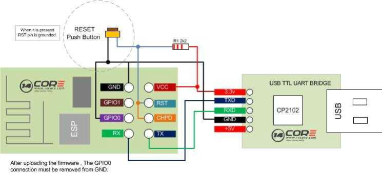
最常用的TTL / FTDI转换器芯片是CH340G,CP2102和FT232RL。我个人使用了前两个,加载程序时没有问题。需要完成以下连接:
| ESP-01S | TTL/FTDI |
|---|---|
| RX | TX |
| TX | RX |
| VCC | 3.3V |
| GND | GND |
| RST | 3.3V/Float |
| CH_PD OR EN | 3.3V |
我强烈建议您不要使用 TTL 3.3v 电源,因为它们中的大多数都无法提供足够的功率来处理 esp8266 arduino 兼容设备。此模块上使用的嵌入式稳压器不是最满意的选择,如果它不支持 ESP 窥视,您可能会遇到麻烦。如果您选择使用外部电源,请不要忘记设置公共接地以获得工作电路。
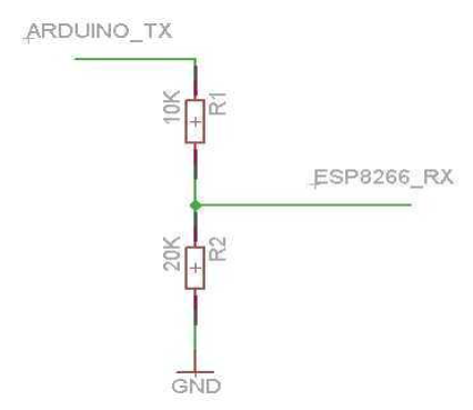
您可以找到 TX 额定值为 3.3v 的 TTL 模块,如果没有,您可以降低 TX 通道以保护您的 ESP-01 模块。您可以在下面看到 ESP-01 和 ESP-01 之间的接线方案
CP2102 包括一个接地的复位按钮,以及用于启动开关的 GPIO0。
下面是使用电阻的简单3.3v除数草图:
为了设置您的 Arduino IDE 以与您的 esp8266 arduino 兼容模块一起使用,您需要执行以下步骤:
-
将 ESP8266-01 模组连接到电脑
-
打开您的Arduino IDE。
-
转到文件 -> 首选项
-
将此链接添加到其他董事会经理
-
转到工具 - >板经理
-
找到 ESP8266 开发板套装并激活
-
从工具->板中选择通用 ESP8266 开发板
-
选择您的编程器COM端口
-
你准备好了!

现在,为了能够将程序下载到您的 ESP-01 模块,您首先需要将设备处于正确的引导模式(从UART下载代码)。ESP8266-01 具有以下开机模式:
| MTDO / GPIO15 | GPIO0 | GPIO2 | Mode | Description |
|---|---|---|---|---|
| L | L | H | UART | Download code from UART |
| L | H | H | Flash | Boot from SPI Flash |
| H | X | X | SDIO | Boot from SD-card |
在从UART下载代码中重置模块后,如果您使用的是正确的波特率,您应该会在串行监视器中看到一条包含“引导模式:[1,6]”的消息。错误的波特率设置将显示垃圾文本/字符或根本不显示任何内容。之后,您应该能够将草图上传到 ESP8266。上传完成后,模块应自行重置。不要忘记拉高GPI0,否则模块将再次进入下载模式,您将无法看到它工作。该模块可以随时通过将 REST 引脚拉至低电平来重新启动。每次重置后,它将遵循引导顺序和程序加载。
一旦在 Arduino IDE 中安装并激活了 ESP8266 板,您就可以在其中包含
所有 ESP WiFi 库和示例。最常用的库是 ESP8266WiFi 提供了许多实现示例,如 WiFiClient、WiFiServer、WiFiAccessPoint 等。你可以在互联网上找到很多项目示例,比如我就在 arduino.com 上找到了很多好点子, 我就在 arduino.cc projecthub 上找到了很多好点子。下面是一个简单的 Arduino 闪烁示例,您可以
您可以用它来测试带有内置 LED 的 esp 模块:
Arduino 闪烁示例
/*
ESP8266 Arduino Blink by Simon Peter
Blink the blue LED on the ESP-01 module
This example code is in the public domain
The blue LED on the ESP-01 module is connected to GPIO1
(which is also the TXD pin; so we cannot use Serial.print() at the same time)
Note that this sketch uses LED_BUILTIN to find the pin with the internal LED
ESP8266 Arduino 闪烁 作者:Simon Peter
闪烁 ESP-01 模块上的蓝色 LED 灯
本示例代码属于公共领域
ESP-01 模块上的蓝色 LED 连接到 GPIO1
(同时也是 TXD 引脚,因此我们不能同时使用 Serial.print())。
请注意,此草图使用 LED_BUILTIN 来查找内部 LED 的引脚
*/
void setup() {
  pinMode(LED_BUILTIN, OUTPUT);  // Initialize the LED_BUILTIN pin as an output
}
// the loop function runs over and over again forever
void loop() {
  digitalWrite(LED_BUILTIN, LOW);  // Turn the LED on (Note that LOW is the voltage level
  // but actually the LED is on; this is because
  // it is acive low on the ESP-01)
  delay(1000);                      // Wait for a second
  digitalWrite(LED_BUILTIN, HIGH);  // Turn the LED off by making the voltage HIGH
  delay(2000);                      // Wait for two seconds (to demonstrate the active low LED)
}
通过 WiFi 将数据发送到 data.spakfun.com 物联网平台
当然,之后您可以通过加载 ESP8266 Arduino WiFi 客户端示例程序来尝试更复杂的示例,该程序通过 WiFi 将数据发送到 data.spakfun.com 物联网平台:
/*
* This sketch sends data via HTTP GET requests to data.sparkfun.com service.
*
* You need to get streamId and privateKey at data.sparkfun.com and paste them
* below. Or just customize this script to talk to other HTTP servers.
* ESP8266 Arduino example
* 该草图通过 HTTP GET 请求向 data.sparkfun.com 服务发送数据。
*
* 您需要从 data.sparkfun.com 获取 streamId 和 privateKey,并将它们粘贴到下面。
* 粘贴到下面。或者自定义此脚本,以便与其他 HTTP 服务器通信。
* ESP8266 Arduino 示例
*/
#include <ESP8266WiFi.h>
const char* ssid = "your-ssid";
const char* password = "your-password";
const char* host = "data.sparkfun.com";
const char* streamId = "....................";
const char* privateKey = "....................";
void setup() {
  Serial.begin(115200);
  delay(10);
  // We start by connecting to a WiFi network
  Serial.println();
  Serial.println();
  Serial.print("Connecting to ");
  Serial.println(ssid);
  WiFi.begin(ssid, password);
  while (WiFi.status() != WL_CONNECTED) {
    delay(500);
    Serial.print(".");
  }
  Serial.println("");
  Serial.println("WiFi connected");
  Serial.println("IP address: ");
  Serial.println(WiFi.localIP());
}
int value = 0;
void loop() {
  delay(5000);
  ++value;
  Serial.print("connecting to ");
  Serial.println(host);
  // Use WiFiClient class to create TCP connections
  WiFiClient client;
  const int httpPort = 80;
  if (!client.connect(host, httpPort)) {
    Serial.println("connection failed");
    return;
  }
  // We now create a URI for the request
  String url = "/input/";
  url += streamId;
  url += "?private_key=";
  url += privateKey;
  url += "&value=";
  url += value;
  Serial.print("Requesting URL: ");
  Serial.println(url);
  // This will send the request to the server
  client.print(String("GET ") + url + " HTTP/1.1\r\n" + "Host: " + host + "\r\n" + "Connection: close\r\n\r\n");
  unsigned long timeout = millis();
  while (client.available() == 0) {
    if (millis() - timeout > 5000) {
      Serial.println(">>> Client Timeout !");
      client.stop();
      return;
    }
  }
  // Read all the lines of the reply from server and print them to Serial
  while (client.available()) {
    String line = client.readStringUntil('\r');
    Serial.print(line);
  }
  Serial.println();
  Serial.println("closing connection");
}
ESP8266 Arduino Wifi 服务器示例程序
或者如果你需要在网络中做一个服务器,可以试试 ESP8266 Arduino Wifi 服务器示例程序:
/*
* This sketch demonstrates how to set up a simple HTTP-like server.
* The server will set a GPIO pin depending on the request
* http://server_ip/gpio/0 will set the GPIO2 low,
* http://server_ip/gpio/1 will set the GPIO2 high
* server_ip is the IP address of the ESP8266 Arduino module, will be
* printed to Serial when the module is connected.
*/
#include <ESP8266WiFi.h>
const char* ssid = "your-ssid";
const char* password = "your-password";
// Create an instance of the server
// specify the port to listen on as an argument
WiFiServer server(80);
void setup() {
  Serial.begin(115200);
  delay(10);
  // prepare GPIO2
  pinMode(2, OUTPUT);
  digitalWrite(2, 0);
  // Connect to WiFi network
  Serial.println();
  Serial.println();
  Serial.print("Connecting to ");
  Serial.println(ssid);
  WiFi.begin(ssid, password);
  while (WiFi.status() != WL_CONNECTED) {
    delay(500);
    Serial.print(".");
  }
  Serial.println("");
  Serial.println("WiFi connected");
  // Start the server
  server.begin();
  Serial.println("Server started");
  // Print the IP address
  Serial.println(WiFi.localIP());
}
void loop() {
  // Check if a client has connected
  WiFiClient client = server.available();
  if (!client) {
    return;
  }
  // Wait until the client sends some data
  Serial.println("new client");
  while (!client.available()) {
    delay(1);
  }
  // Read the first line of the request
  String req = client.readStringUntil('\r');
  Serial.println(req);
  client.flush();
  // Match the request
  int val;
  if (req.indexOf("/gpio/0") != -1)
    val = 0;
  else if (req.indexOf("/gpio/1") != -1)
    val = 1;
  else {
    Serial.println("invalid request");
    client.stop();
    return;
  }
  // Set GPIO2 according to the request
  digitalWrite(2, val);
  client.flush();
  // Prepare the response
  String s = "HTTP/1.1 200 OK\r\nContent-Type: text/html\r\n\r\n<!DOCTYPE
             HTML
             >\r\n<html>\r\nGPIO is now ";
             s += (val) ? "high" : "low";
  s += "</html>\n";
  // Send the response to the client
  client.print(s);
  delay(1);
  erial.println("Client disonnected");
  // The client will actually be disconnected
  // when the function returns and 'client' object is detroyed
}
创建了托管 Web 服务器的 ESP8266 Arduino WiFi 接入点示例:
/* Create a WiFi access point and provide a web server on it.
ESP8266 Arduino example
创建一个 WiFi 接入点,并在其上提供网络服务器。
ESP8266 Arduino 示例
*/
#include <ESP8266WiFi.h>
#include <WiFiClient.h>
#include <ESP8266WebServer.h>
/* Set these to your desired credentials. */
const char *ssid = "ESPap";
const char *password = "thereisnospoon";
ESP8266WebServer server(80);
/* Just a little test message. Go to http://192.168.4.1 in a web browser
* connected to this access point to see it.
*/
void handleRoot() {
  server.send(200, "text/html", "<h1>You are connected</h1>");
}
void setup() {
  delay(1000);
  Serial.begin(115200);
  Serial.println();
  Serial.print("Configuring access point...");
  /* You can remove the password parameter if you want the AP to be open. */
  WiFi.softAP(ssid, password);
  IPAddress myIP = WiFi.softAPIP();
  Serial.print("AP IP address: ");
  Serial.println(myIP);
  server.on("/", handleRoot);
  server.begin();
  Serial.println("HTTP server started");
}
void loop() {
  server.handleClient();
}





![LeetCode[1122]数组的相对排序](https://img-blog.csdnimg.cn/5179b0e80d134eeb9776e7d596d7f35f.png)


