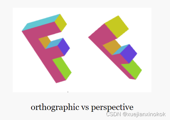
在上一篇文章中,介绍了如何制作 3D ,但 3D 没有任何透视效果。它使用的是所谓的“正交”视图,它有其用途,但通常不是人们说“3D”时想要的。
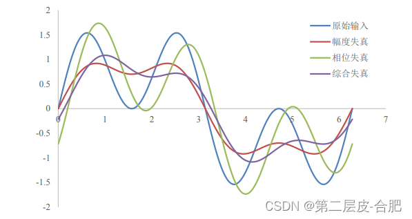
现在,需要添加透视图。究竟什么是透视?基本特征就是离得越远的东西显得越小。
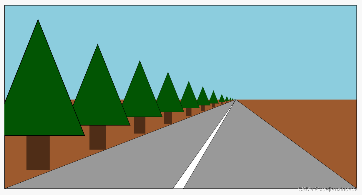
看看上面的例子,远处的东西被画得更小了。给定我们当前的示例,一种使距离更远的东西看起来更小的简单方法是将剪辑空间 X 和 Y 除以 Z。
Think of it this way: If you have a line from (10, 15) to (20,15) it’s 10 units long. In our current sample it would be drawn 10 pixels long. But if we divide by Z then for example if Z is 1
这样想:如果你有一条从 (10, 15) 到 (20,15) 的线,它有 10 个单位长。在我们当前的示例中,它将被绘制为 10 像素长。但是如果我们除以 Z 那么如果 Z 是 1
10 / 1 = 10
20 / 1 = 20
abs(10-20) = 10
它将有 10 个像素长,如果 Z 为 2,则为
10 / 2 = 5
20 / 2 = 10
abs(5 - 10) = 5
5 像素长。在 Z = 3 时,它将是
10 / 3 = 3.333
20 / 3 = 6.666
abs(3.333 - 6.666) = 3.333
You can see that as Z increases, as it gets smaller, we’ll end up drawing it smaller, and therefore it will appear further way. If we divide in clip space we might get better results because Z will be a smaller number (0 to +1). If we add a fudgeFactor to multiply Z before we divide we can adjust how much smaller things get for a given distance.
你可以看到随着 Z 的增加,它变小,最终会把它画得更小,因此它会看起来更远。如果在剪辑空间中划分,可能会得到更好的结果,因为 Z 将是一个较小的数字(0 到 +1)。如果我们在除法之前添加一个 fudgeFactor 来乘以 Z,我们可以调整给定距离的东西变小的程度。
让我们试试吧。首先让将顶点着色器更改为在乘以我们的“fudgeFactor”后除以 Z。
struct Uniforms {
  matrix: mat4x4f,
  fudgeFactor: f32, //here
};

struct Vertex {
  @location(0) position: vec4f,
  @location(1) color: vec4f,
};

struct VSOutput {
  @builtin(position) position: vec4f,
  @location(0) color: vec4f,
};

@group(0) @binding(0) var<uniform> uni: Uniforms;

@vertex fn vs(vert: Vertex) -> VSOutput {
  var vsOut: VSOutput;
  //vsOut.position = uni.matrix * vert.position;
  let position = uni.matrix * vert.position;

  let zToDivideBy = 1.0 + position.z * uni.fudgeFactor;

  vsOut.position = vec4f(
      position.xy / zToDivideBy,
      position.zw);

  vsOut.color = vert.color;
  return vsOut;
}
Note: By adding 1 we can set fudgeFactor to 0 and get a zToDivideBy that is equal to 1. This will let is compare when not dividing by Z because dividing by 1 does nothing.
注意:通过加 1,我们可以将 fudgeFactor 设置为 0 并得到等于 1 的 zToDivideBy 。这将在不除以 Z 时进行比较,因为除以 1 什么都不做。
还需要更新代码来设置 fudgeFactor。
  // matrix
  // const uniformBufferSize = (16) * 4;
  // matrix, fudgeFactor, padding
  const uniformBufferSize = (16 + 1 + 3) * 4;
  const uniformBuffer = device.createBuffer({
    label: 'uniforms',
    size: uniformBufferSize,
    usage: GPUBufferUsage.UNIFORM | GPUBufferUsage.COPY_DST,
  });

  const uniformValues = new Float32Array(uniformBufferSize / 4);

  // offsets to the various uniform values in float32 indices
  const kMatrixOffset = 0;
  const kFudgeFactorOffset = 16; //here

  const matrixValue = uniformValues.subarray(kMatrixOffset, kMatrixOffset + 16);
  const fudgeFactorValue = uniformValues.subarray(kFudgeFactorOffset, kFudgeFactorOffset + 1); //here

...

  const settings = {
    translation: [canvas.clientWidth / 2 - 200, canvas.clientHeight / 2 - 75, -1000],
    rotation: [degToRad(40), degToRad(25), degToRad(325)],
    scale: [3, 3, 3],
    fudgeFactor: 0.5, //here
  };

...

  const gui = new GUI();
  gui.onChange(render);
  gui.add(settings.translation, '0', 0, 1000).name('translation.x');
  gui.add(settings.translation, '1', 0, 1000).name('translation.y');
  gui.add(settings.translation, '2', -1000, 1000).name('translation.z');
  gui.add(settings.rotation, '0', radToDegOptions).name('rotation.x');
  gui.add(settings.rotation, '1', radToDegOptions).name('rotation.y');
  gui.add(settings.rotation, '2', radToDegOptions).name('rotation.z');
  gui.add(settings.scale, '0', -5, 5).name('scale.x');
  gui.add(settings.scale, '1', -5, 5).name('scale.y');
  gui.add(settings.scale, '2', -5, 5).name('scale.z');
  gui.add(settings, 'fudgeFactor', 0, 50); //here

...

  function render() {

    ...

    mat4.ortho(
        0,                   // left
        canvas.clientWidth,  // right
        canvas.clientHeight, // bottom
        0,                   // top
        1200,                // near
        -1000,               // far
        matrixValue,         // dst
    );
    mat4.translate(matrixValue, settings.translation, matrixValue);
    mat4.rotateX(matrixValue, settings.rotation[0], matrixValue);
    mat4.rotateY(matrixValue, settings.rotation[1], matrixValue);
    mat4.rotateZ(matrixValue, settings.rotation[2], matrixValue);
    mat4.scale(matrixValue, settings.scale, matrixValue);

    fudgeFactorValue[0] = settings.fudgeFactor; //here
还调整了 settings 以希望能够轻松查看结果。
const settings = {
   // translation: [45, 100, 0],
    translation: [canvas.clientWidth / 2 - 200, canvas.clientHeight / 2 - 75, -1000],
    rotation: [degToRad(40), degToRad(25), degToRad(325)],
   // scale: [1, 1, 1],
    scale: [3, 3, 3],
    fudgeFactor: 10,
  };
这是结果。
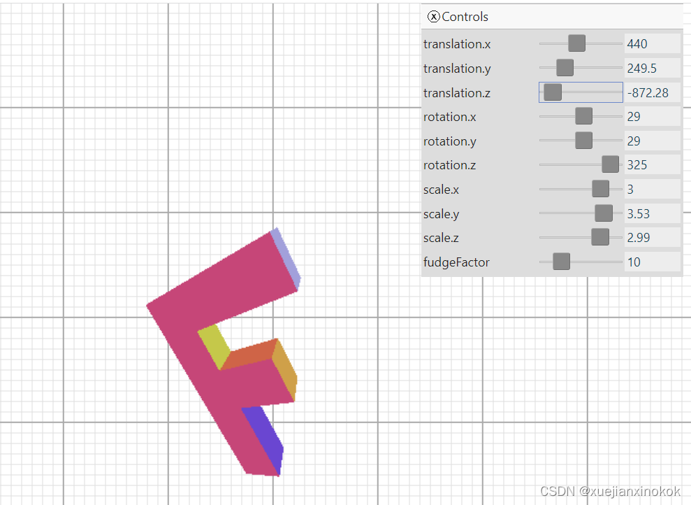
如果不清楚,请将“fudgeFactor”滑块从 10.0 拖动到 0.0,以查看在我们添加除以 Z 代码之前的样子。
事实证明,WebGPU 采用分配给顶点着色器 @builtin(position) 的 x、y、z、w 值,并自动将其除以 w。
可以很容易地通过改变着色器来证明这一点,而不是自己做除法,把 zToDivideBy 放在 vsOut.position.w 中。
@vertex fn vs(vert: Vertex) -> VSOutput {
  var vsOut: VSOutput;
  let position = uni.matrix * vert.position;

  let zToDivideBy = 1.0 + position.z * uni.fudgeFactor;

 // vsOut.position = vec4f(
 //     position.xy / zToDivideBy,
 //     position.zw);
  vsOut.position = vec4f(position.xyz, zToDivideBy); //here

  vsOut.color = vert.color;
  return vsOut;
}
看看它是如何完全一样的。
为什么 WebGPU 自动除以 W 有用?因为现在,使用更多的矩阵魔法,我们可以只使用另一个矩阵将 z 复制到 w。
像这样的矩阵
1  0  0  0
0  1  0  0
0  0  1  0
0  0  1  0
将 z 复制到 w。您可以将这些行中的每一行视为
x_out = x_in * 1 +
        y_in * 0 +
        z_in * 0 +
        w_in * 0 ;
y_out = x_in * 0 +
y_in * 1 +
z_in * 0 +
w_in * 0 ;


z_out = x_in * 0 +
y_in * 0 +
z_in * 1 +
w_in * 0 ;


w_out = x_in * 0 +
y_in * 0 +
z_in * 1 +
w_in * 0 ;
简化后是
x_out = x_in;
y_out = y_in;
z_out = z_in;
w_out = z_in;
由于我们知道 w_in 始终为 1.0,因此我们可以将之前的加 1 添加到此矩阵中。
1  0  0  0
0  1  0  0
0  0  1  0
0  0  1  1
这会将 W 计算更改为
w_out = x_in * 0 +
        y_in * 0 +
        z_in * 1 +
        w_in * 1 ;
and since we know w_in = 1.0 then that’s really
因为我们知道 w_in = 1.0 那么这真的
w_out = z_in + 1;
最后,如果矩阵是这样的话,我们可以重新使用 fudgeFactor
1  0  0            0
0  1  0            0
0  0  1            0
0  0  fudgeFactor  1
意思是
w_out = x_in * 0 +
        y_in * 0 +
        z_in * fudgeFactor +
        w_in * 1 ;
并简化为
w_out = z_in * fudgeFactor + 1;
因此,让我们再次修改程序以仅使用矩阵。
首先把顶点着色器修改改回去,这样又简单了
struct Uniforms {
  matrix: mat4x4f,
  //fudgeFactor: f32,
};

struct Vertex {
  @location(0) position: vec4f,
  @location(1) color: vec4f,
};

struct VSOutput {
  @builtin(position) position: vec4f,
  @location(0) color: vec4f,
};

@group(0) @binding(0) var<uniform> uni: Uniforms;

@vertex fn vs(vert: Vertex) -> VSOutput {
  var vsOut: VSOutput;
  //let position = uni.matrix * vert.position;

 // let zToDivideBy = 1.0 + position.z * uni.fudgeFactor;

 // vsOut.position = vec4f(
 //     position.xy / zToDivideBy,
 //     position.zw);
  vsOut position = uni.matrix * vert.position;
  vsOut.color = vert.color;
  return vsOut;
}

@fragment fn fs(vsOut: VSOutput) -> @location(0) vec4f {
  return vsOut.color;
}
接下来创建一个函数来生成 Z → W 矩阵。
function makeZToWMatrix(fudgeFactor) {
  return [
    1, 0, 0, 0,
    0, 1, 0, 0,
    0, 0, 1, fudgeFactor,
    0, 0, 0, 1,
  ];
}
更改代码以使用它。
 //mat4.ortho(
    const projection = mat4.ortho(
        0,                   // left
        canvas.clientWidth,  // right
        canvas.clientHeight, // bottom
        0,                   // top
        1200,                // near
        -1000,               // far
       // matrixValue,         // dst
    );
    mat4.multiply(makeZToWMatrix(settings.fudgeFactor), projection, matrixValue);
    mat4.translate(matrixValue, settings.translation, matrixValue);
    mat4.rotateX(matrixValue, settings.rotation[0], matrixValue);
    mat4.rotateY(matrixValue, settings.rotation[1], matrixValue);
    mat4.rotateZ(matrixValue, settings.rotation[2], matrixValue);
    mat4.scale(matrixValue, settings.scale, matrixValue);
再次注意,它是完全一样的。
All that was basically just to show you that dividing by Z gives us perspective and that WebGPU conveniently does this divide by Z for us.
所有这些基本上只是为了展示除以 Z 给我们提供了视角,而 WebGPU 可以方便地为我们除以 Z。
但仍然存在一些问题。例如,如果将 Z 设置为 -1100 左右,您将看到类似下面的动画
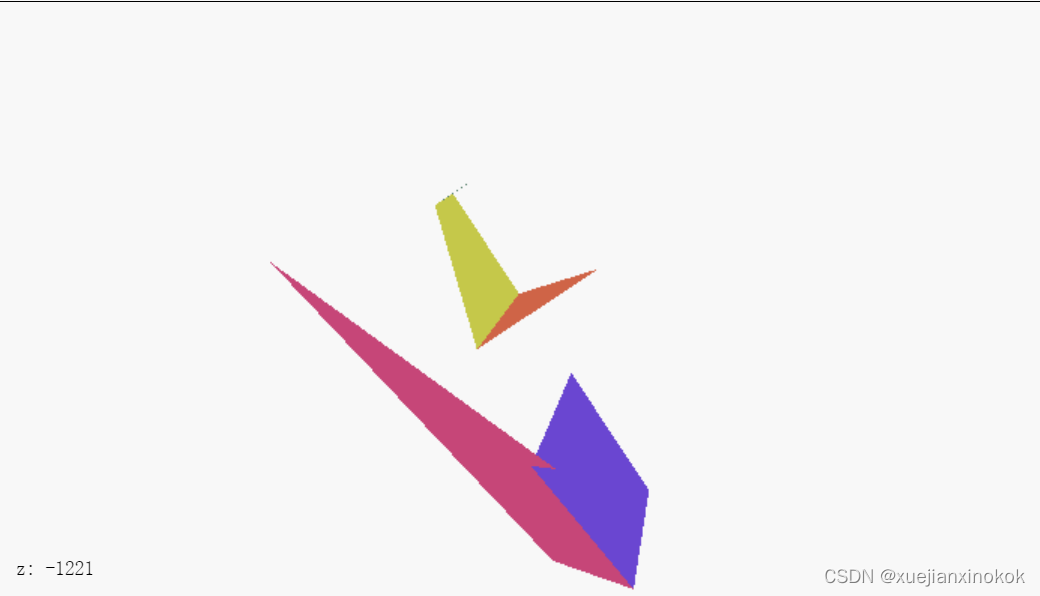
What’s going on? Why is the F disappearing early? Just like WebGPU clips X and Y or +1 to -1 it also clips Z. Unlike X and Y, Z clips 0 to +1. What we’re seeing here is Z < 0 in clip space.
这是怎么回事?为什么F早早消失了?就像 WebGPU 剪辑 X 和 Y 或 +1 到 -1 一样,它也剪辑 Z。与 X 和 Y 不同,Z 剪辑 0 到 +1。我们在这里看到的是裁剪空间中的 Z < 0。
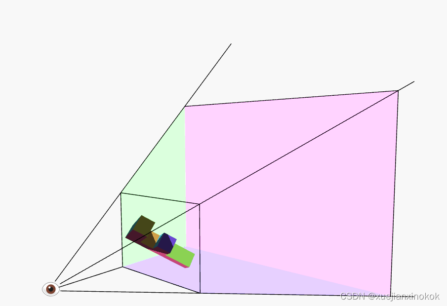
With with divide by W in place, our matrix math + the divide by W defines a frustum. The front of the frustum is Z = 0, the back is Z = 1. Anything outside of that is clipped.
通过除以 W,我们的矩阵数学 + 除以 W 定义了一个视锥体。视锥体的前面是 Z = 0,后面是 Z = 1。外面的任何东西都被剪掉了。
frustum 截锥体
noun: 名词:
a cone or pyramid with the upper part cut off by a plane parallel to its base
上部被平行于其底面的平面截断的圆锥体或棱锥体
I could go into detail about the math to fix it but you can derive it the same way we did 2D projection. We need to take Z, add some amount (translation) and scale some amount and we can make any range we want get remapped to the -1 to +1.
我可以详细介绍数学来修复它,但您可以像我们做 2D 投影一样推导它。我们需要获取 Z,添加一些数量(平移)并缩放一些数量,我们可以将我们想要的任何范围重新映射到 -1 到 +1。
很酷的是所有这些步骤都可以在 1 个矩阵中完成。更好的是,我们将决定 fieldOfView 而不是 fudgeFactor 并计算正确的值来实现这一点。
这是一个构建矩阵的函数。
const mat4 = {
  ...
  perspective(fieldOfViewYInRadians, aspect, zNear, zFar, dst) {
    dst = dst || new Float32Array(16);

    const f = Math.tan(Math.PI * 0.5 - 0.5 * fieldOfViewYInRadians);
    const rangeInv = 1 / (zNear - zFar);

    dst[0] = f / aspect;
    dst[1] = 0;
    dst[2] = 0;
    dst[3] = 0;

    dst[4] = 0;
    dst[5] = f;
    dst[6] = 0;
    dst[7] = 0;

    dst[8] = 0;
    dst[9] = 0;
    dst[10] = zFar * rangeInv;
    dst[11] = -1;

    dst[12] = 0;
    dst[13] = 0;
    dst[14] = zNear * zFar * rangeInv;
    dst[15] = 0;

    return dst;
  }
This matrix will do all our conversions for us. It will adjust the units so they are in clip space, it will do the math so that we can choose a field of view by angle and it will let us choose our Z-clipping space. It assumes there’s an eye or camera at the origin (0, 0, 0) and given a zNear and a fieldOfView it computes what it would take so that stuff at zNear ends up at Z = 0 and stuff at zNear that is half of fieldOfView above or below the center ends up with Y = -1 and Y = 1 respectively. It computes what to use for X by just multiplying by the aspect passed in. We’d normally set this to the width / height of the display area. Finally, it figures out how much to scale things in Z so that stuff at zFar ends up at Z = 1.
该矩阵将为我们完成所有转换。它会调整单位,使它们在裁剪空间中,它会进行数学计算,以便我们可以按角度选择视野,它会让我们选择我们的 Z 裁剪空间。它假设在原点 (0, 0, 0) 处有一只眼睛或相机,并给定一个 zNear 和一个 fieldOfView 它计算它需要什么,以便 zNear 的东西最终在 Z = 0 和东西在 zNear 是中心上方或下方 fieldOfView 的一半,分别以 Y = -1 和 Y = 1 结尾。它通过乘以传入的 aspect 来计算用于 X 的内容。我们通常将其设置为显示区域的 width / height 。最后,它计算出在 Z 中缩放多少东西,以便 zFar 中的东西最终达到 Z = 1 。
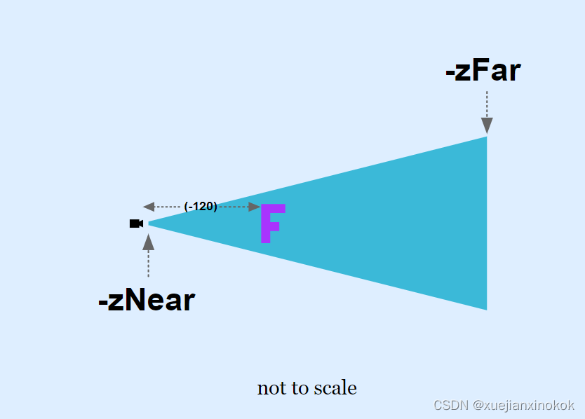
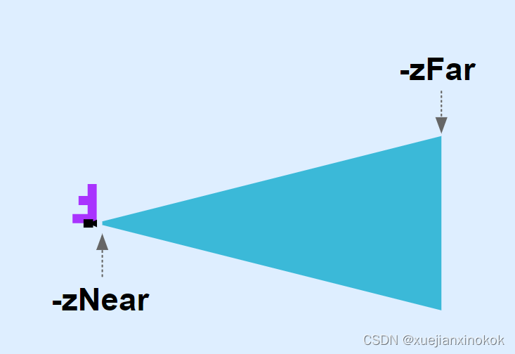
Here’s a diagram of the matrix in action.
这是矩阵的示意图。
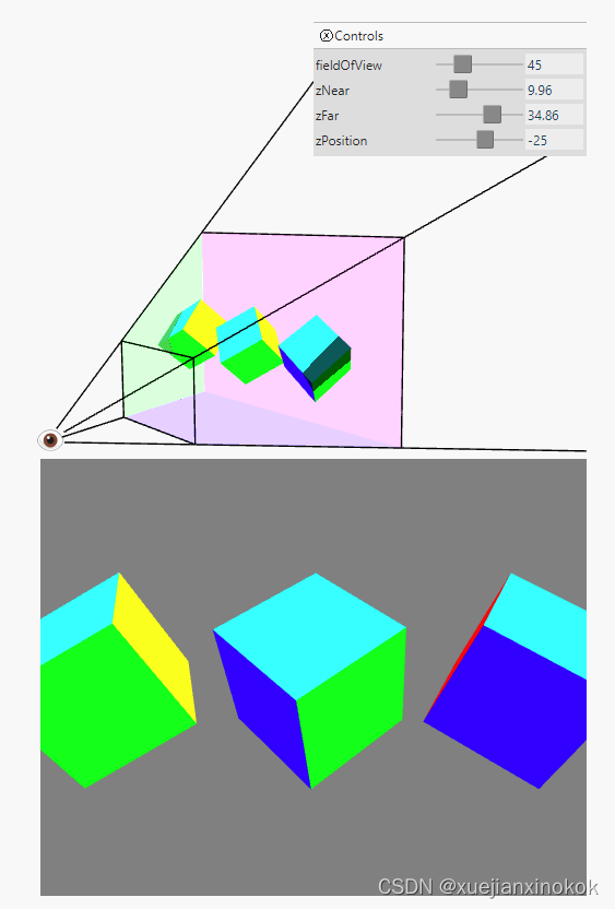
The matrix takes the space inside the frustum and converts that to clip space. zNear defines where things will get clipped in the front and zFar defines where things get clipped in the back. Set zNear to 23 and you’ll see the front of the spinning cubes get clipped. Set zFar to 24 and you’ll see the back of the cubes get clipped.
矩阵采用视锥体内的空间并将其转换为裁剪空间。 zNear 定义了前面的内容被剪裁的位置, zFar 定义了后面的内容被剪裁的位置。将 zNear 设置为 23,您会看到旋转立方体的前部被剪裁。将 zFar 设置为 24,您会看到立方体的背面被剪裁了。
让我们在示例中使用此功能。
 const settings = {
    fieldOfView: degToRad(100),
    translation: [canvas.clientWidth / 2 - 200, canvas.clientHeight / 2 - 75, -1000],
    rotation: [degToRad(40), degToRad(25), degToRad(325)],
    scale: [3, 3, 3],
    //fudgeFactor: 10,
  };

  const radToDegOptions = { min: -360, max: 360, step: 1, converters: GUI.converters.radToDeg };

  const gui = new GUI();
  gui.onChange(render);
  gui.add(settings, 'fieldOfView', {min: 1, max: 179, converters: GUI.converters.radToDeg});
  gui.add(settings.translation, '0', 0, 1000).name('translation.x');
  gui.add(settings.translation, '1', 0, 1000).name('translation.y');
  gui.add(settings.translation, '2', -1400, 1000).name('translation.z');
  gui.add(settings.rotation, '0', radToDegOptions).name('rotation.x');
  gui.add(settings.rotation, '1', radToDegOptions).name('rotation.y');
  gui.add(settings.rotation, '2', radToDegOptions).name('rotation.z');
  gui.add(settings.scale, '0', -5, 5).name('scale.x');
  gui.add(settings.scale, '1', -5, 5).name('scale.y');
  gui.add(settings.scale, '2', -5, 5).name('scale.z');
  //gui.add(settings, 'fudgeFactor', 0, 50);

  ...

  function render() {
    ....

    //const projection = mat4.ortho(
    //    0,                   // left
    //    canvas.clientWidth,  // right
    //    canvas.clientHeight, // bottom
    //    0,                   // top
    //    1200,                // near
    //    -1000,               // far
    //);
    //mat4.multiply(makeZToWMatrix(settings.fudgeFactor), projection, matrixValue);
// mat4.multiply(makeZToWMatrix(settings.fudgeFactor), projection, matrixValue);
    const aspect = canvas.clientWidth / canvas.clientHeight;
    mat4.perspective(
        settings.fieldOfView,
        aspect,
        1,      // zNear
        2000,   // zFar
        matrixValue,
    );
    mat4.translate(matrixValue, settings.translation, matrixValue);
    mat4.rotateX(matrixValue, settings.rotation[0], matrixValue);
    mat4.rotateY(matrixValue, settings.rotation[1], matrixValue);
    mat4.rotateZ(matrixValue, settings.rotation[2], matrixValue);
    mat4.scale(matrixValue, settings.scale, matrixValue);
There’s just one problem left. This projection matrix assumes there’s a viewer at 0,0,0 and it assumes it’s looking in the negative Z direction and that positive Y is up. Our matrices up to this point have done things in a different way. We need to put the F, which is 150 units tall, 100 units wide, and 30 units thick, in some -Z position and it needs to be far enough away that it fits inside the frustum. The frustum we’ve defined above, with zNear = 1 will only show about 2.4 units from top to bottom when an object is 1 unit away so our F will be %98 off the screen.
只剩下一个问题了。这个投影矩阵假设在 0,0,0 处有一个观察者,并且假设它在负 Z 方向看,并且正 Y 向上。到目前为止,我们的矩阵以不同的方式做事。我们需要将 150 个单位高、100 个单位宽和 30 个单位厚的 F 放在某个 -Z 位置,并且它需要离得足够远以适合平截头体。我们在上面定义的截锥体, zNear = 1 当对象距离 1 个单位时,从上到下仅显示大约 2.4 个单位,因此我们的 F 将离开屏幕 %98。
Playing around with some numbers I came up with these settings.
玩弄一些数字,我想出了这些设置。
const settings = {
    fieldOfView: degToRad(100),
   // translation: [canvas.clientWidth / 2 - 200, canvas.clientHeight / 2 - 75, -1000],
   // rotation: [degToRad(40), degToRad(25), degToRad(325)],
   // scale: [3, 3, 3],
    translation: [-65, 0, -120],
    rotation: [degToRad(220), degToRad(25), degToRad(325)],
    scale: [1, 1, 1],
  };
hide deleted
And, while we’re at it let’s adjust the UI settings to be more appropriate. Let’s also remove the scale to unclutter to UI a little.
而且,当我们这样做时,让我们调整 UI 设置以使其更合适。让我们也移除比例以使 UI 更整洁一些。
const gui = new GUI();
  gui.onChange(render);
  gui.add(settings, 'fieldOfView', {min: 1, max: 179, converters: GUI.converters.radToDeg});
  //gui.add(settings.translation, '0', 0, 1000).name('translation.x');
  //gui.add(settings.translation, '1', 0, 1000).name('translation.y');
  //gui.add(settings.translation, '2', -1400, 1000).name('translation.z');
  gui.add(settings.translation, '0', -1000, 1000).name('translation.x');
  gui.add(settings.translation, '1', -1000, 1000).name('translation.y');
  gui.add(settings.translation, '2', -1400, -100).name('translation.z');
  gui.add(settings.rotation, '0', radToDegOptions).name('rotation.x');
  gui.add(settings.rotation, '1', radToDegOptions).name('rotation.y');
  gui.add(settings.rotation, '2', radToDegOptions).name('rotation.z');
  //gui.add(settings.scale, '0', -5, 5).name('scale.x');
  //gui.add(settings.scale, '1', -5, 5).name('scale.y');
  //gui.add(settings.scale, '2', -5, 5).name('scale.z');
Let’s also get rid of the grid since we’re no longer in “pixel space”.
让我们也摆脱网格,因为我们不再处于“像素空间”中。
:root {
  --bg-color: #fff;
}
@media (prefers-color-scheme: dark) {
  :root {
    --bg-color: #000;
  }
}
canvas {
  display: block;  /* make the canvas act like a block   */
  width: 100%;     /* make the canvas fill its container */
  height: 100%;
}
就在这里。
We’re back to just a matrix multiply on our shader and we’re getting both a field of view and we’re able to choose our Z space.
我们回到了我们的着色器上的矩阵乘法,我们得到了一个视野并且我们能够选择我们的 Z 空间。
接下来,是相机。
为什么我们将 F 在 Z (-120) 中移动这么远?
In the other samples we had the F at (45, 100, 0) but in the last sample it’s been moved to (-65, 0, -120). Why did it need to be moved so far away?
在其他示例中,我们将 F 设置为 (45, 100, 0),但在最后一个示例中,它已移至 (-65, 0, -120)。为什么需要将它移到这么远的地方?
The reason is up until this last sample our mat4.projection function made a projection from pixels to clip space. That means the area we were displaying kinda of represented pixels. Using ‘pixels’ really doesn’t make sense in 3D since it would only represent pixels at a specific distance from the camera.
原因是在最后一个样本之前,我们的 mat4.projection 函数从像素到裁剪空间进行了投影。这意味着我们显示的区域有点代表像素。在 3D 中使用“像素”确实没有意义,因为它只代表距相机特定距离的像素。
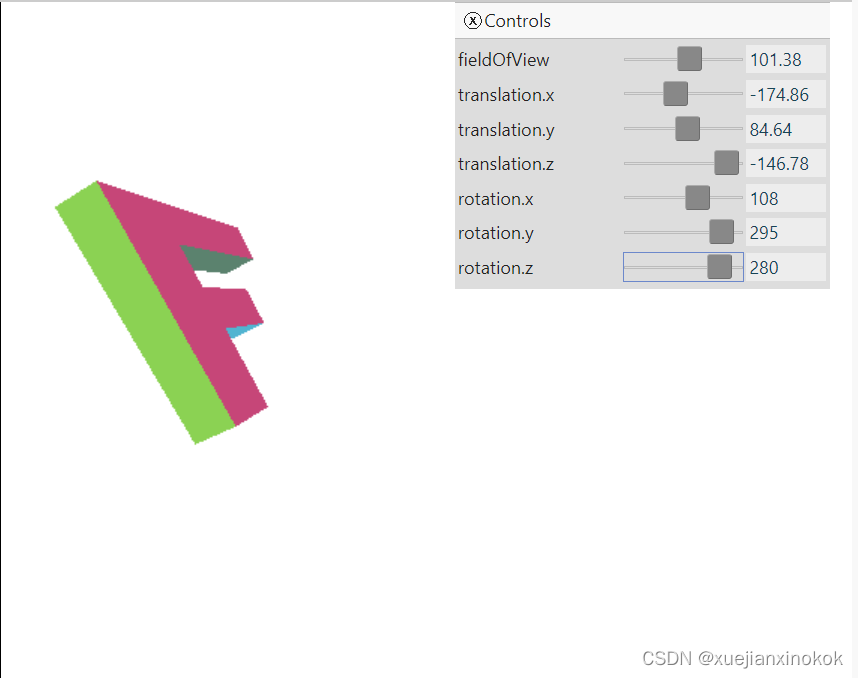
In other words, with our new perspective projection matrix, if we tried to draw with the F with translation at 0,0,0 and rotation 0,0,0 it we’d get this
换句话说,使用我们新的透视投影矩阵,如果我们尝试使用平移为 0,0,0 且旋转为 0,0,0 的 F 进行绘制,我们会得到这个
The F has its top left front corner at the origin. The perspective projection matrix looks toward negative Z but our F is built in positive Z. The perspective projection matrix has positive Y up but our F is built with positive Z down.
F 的左上角位于原点。透视投影矩阵朝负 Z 方向看,但我们的 F 建立在正 Z 中。透视投影矩阵具有正 Y 向上但我们的 F 建立正 Z 向下。
Our new projection only sees what’s in the blue frustum. With -zNear = 1 and with a field of view of 100 degrees then at Z = -1 the frustum is only 2.38 units tall and 2.38 * aspect units wide. At Z = -2000 (-zFar) its 4767 units tall. Since our F is 150 units big and the view can only see 2.38 units when something is at -zNear we need to move it further away from the origin to see all of it.
我们的新投影只能看到蓝色截锥体中的内容。在 -zNear = 1 且视野为 100 度的情况下,在 Z = -1 时,平截头体只有 2.38 个单位高和 2.38 * 纵横比单位宽。在 Z = -2000 (-zFar) 处,它有 4767 个单位高。由于我们的 F 有 150 个单位大,当某些东西位于 -zNear 时视图只能看到 2.38 个单位,我们需要将它移到离原点更远的地方才能看到所有的东西。
Moving it -120 units in Z moves the F inside the frustum. We also rotated it to be right side up.
将它在 Z 中移动 -120 个单位会将 F 移动到平截头体内。我们还将其旋转为正面朝上。