1. 功能说明
本文示例将实现R253样机8自由度串联四足机器人前进的功能,该机构是由4个 2自由度串联仿生腿 组成。
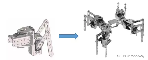
2. 串联关节型机器人运动算法
8自由度串联四足机器人的前进步态是将机器人四足分成两组腿(身体一侧的前足与另一侧的后足)分别进行摆动和支撑,即处于对角线上的两条腿的动作一样,均处于摆动相或均处于支撑相,如下图所示:
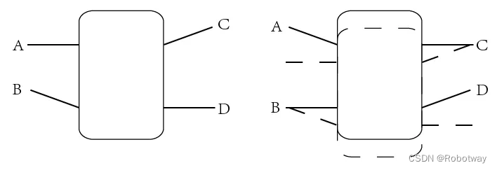
当转向时对角线上的腿部摆动方向会跟前进步态不一样,如下图所示为一个左转的步态:

3. 电子硬件
本实验中采用了以下硬件:
| 主控板 | Basra主控板(兼容Arduino Uno) |
| 扩展板 | Bigfish2.1扩展板 |
| 电池 | 7.4V锂电池 |
电路连接说明: D3、D4;D7、D 8;D11、D12;A2、A3为舵机引脚分别对应8自由度串联四足机器人在Bigfish扩展板上的连接位置
【注意:两个舵机为一条腿,不要分开连接】
这里需要注意下,因为该机器人结构上有8个舵机,而Bigfish扩展板上的舵机接口是6个,所以我们需要对Bigfish扩展板进行改装(通过跳线的方式将Bigfish扩展板上常规使用的传感器接口转为舵机接口)。
4. 功能实现
编程环境:Arduino 1.8.19
下面提供一个8自由度串联四足机器人步态前进的参考例程(_1_17.ino),将参考例程下载到主控板中,具体实验效果可参考官网演示视频。
/*------------------------------------------------------------------------------------

  版权说明:Copyright 2023 Robottime(Beijing) Technology Co., Ltd. All Rights Reserved.

           Distributed under MIT license.See file LICENSE for detail or copy at

           https://opensource.org/licenses/MIT

           by 机器谱 2023-04-20 https://www.robotway.com/

  ------------------------------*/

/*------------------------------------------------------------------------------------

  实验功能:

    八自由度四足机器人运动


  实验接线:

                【--机器人头部(俯视图)--】

----------------------------------------------------


    左前腿[外侧腿----内侧腿]     右前腿[内侧腿----外侧腿]

            内侧    外侧                 内侧     外侧

             .--.      .--.                    .--.       .--.

             |   |---|   |                     |   |       |   |

    D3    |   |---|   |   D4        D7 |   |       |   | D8

             ---*   ---*                    *--*     *--*


    左后腿[外侧腿----内侧腿]     右后腿[内侧腿----外侧腿]

           内侧    外侧                  内侧     外侧

            .--.      .--.                    .--.       .--.

            |   |---|   |                     |   |      |   |

    A3   |   |---|   |   A2       D12 |   |      |   | D11

            ---*   ---*                    *--*    *--*

    ---------------------------------------------------

  版权说明:Copyright 2023 Robottime(Beijing) Technology Co., Ltd. All Rights Reserved.

    Distributed under MIT license.See file LICENSE for detail or copy at

     https://opensource.org/licenses/MIT   by 机器谱 2023-04-20 https://www.robotway.com/

-------------------------------------------------------------------------------------*/

#include <Arduino.h>

#include <avr/pgmspace.h>

#include <Servo.h>

#include "Config.h"

#include "PROGMEM_DATA.h"


Servo myServo[8];


void act_length();      //动作数组长度计算

void ServoStart();      //舵机连接

void ServoStop();       //舵机断开

void ServoGo();         //舵机转动

void readProgmem();     //读取PWM值

void servo_init();      //舵机初始化

void servo_move();      //动作执行


void setup() {

  Serial.begin(9600);

  act_length();

}


void loop() {

  servo_move(ACTION_INIT, 2);

  delay(1000);

  servo_move(ACTION_MOVE, 20);

  while(1){};

}


void act_length()

{

  actPwmNum[0] = (sizeof(actionInit) / sizeof(actionInit[0]))/SERVO_NUM;

  actPwmNum[1] = (sizeof(actionMove) / sizeof(actionMove[0]))/SERVO_NUM;

  actPwmNum[2] = (sizeof(actionBack) / sizeof(actionBack[0]))/SERVO_NUM;

  actPwmNum[3] = (sizeof(actionLeft) / sizeof(actionLeft[0]))/SERVO_NUM;

  actPwmNum[4] = (sizeof(actionRight) / sizeof(actionRight[0]))/SERVO_NUM;


  /*******************+++++++++此处可以添加PWM数组++++++++++++****************/

}


void ServoStart(int which){

  if(!myServo[which].attached())myServo[which].attach(servo_port[which]);

  pinMode(servo_port[which], OUTPUT);

}


void ServoStop(int which){

  myServo[which].detach();

  digitalWrite(servo_port[which],LOW);

}


void ServoGo(int which , float where){

  ServoStart(which);

  myServo[which].writeMicroseconds(where);

}


void readProgmem(int p, int act){

  switch(act)

  {

    case 0:   value_cur[p] = pgm_read_word_near(actionInit + p + (SERVO_NUM * count_input));   break;

    case 1:   value_cur[p] = pgm_read_word_near(actionMove + p + (SERVO_NUM * count_input));   break;

    case 2:   value_cur[p] = pgm_read_word_near(actionBack + p + (SERVO_NUM * count_input));   break;

    case 3:   value_cur[p] = pgm_read_word_near(actionLeft + p + (SERVO_NUM * count_input));   break;

    case 4:   value_cur[p] = pgm_read_word_near(actionRight + p + (SERVO_NUM * count_input));   break;

    default: break;

  }

}


void servo_init(int act, int num){

  if(!_b)

  {

    for(int i=0;i<SERVO_NUM;i++)

    {

      readProgmem(i, act);

      ServoGo(i, value_cur[i]);

      value_pre[i] = value_cur[i];

    }

  }

  num == 1 ? _b = true : _b = false;

}


void servo_move(int act, int num){

  float value_delta[SERVO_NUM] = {};

  float in_value[SERVO_NUM] = {};

  servo_init(act, num);

  for(int i=0;i< num * actPwmNum[act];i++)

  {

    count_input++;


    if(count_input == actPwmNum[act])

    {

      count_input = 0;

      continue;

    }


    for(int i=0;i<SERVO_NUM;i++)

    {

      readProgmem(i, act);

      in_value[i] = value_pre[i];

      value_delta[i] = (value_cur[i] - value_pre[i]) / frequency;


      /**************************************************串口查看输出**************************************************/

//      Serial.print(value_pre[i]);

//      Serial.print(" ");

//      Serial.print(value_cur[i]);

//      Serial.print(" ");

//      Serial.print(value_delta[i]);

//      Serial.println();

      /**************************************************串口查看输出**************************************************/

    }

//    Serial.println();


    for(int i=0;i<frequency;i++)

    {

      for(int k=0;k<SERVO_NUM;k++)

      {

        in_value[k] += value_delta[k];

        value_pre[k] = in_value[k];


        /**************************************************串口查看输出**************************************************/

//        Serial.print(in_value[k]);

//        Serial.print(" ");

        /**************************************************串口查看输出**************************************************/

      }

//      Serial.println();


      for(int j=0;j<SERVO_NUM;j++)

      {

        ServoGo(j, in_value[j]);

      }

      delayMicroseconds(SERVO_SPEED);

    }


    /**************************************************串口查看输出**************************************************/

//    for(int i=0;i<SERVO_NUM;i++)

//    {

//      Serial.println(value_pre[i]);

//    }

    /**************************************************串口查看输出**************************************************/

  }

}
大家可根据转向的步态,参考上述例程,尝试自己编写下8自由度串联四足机器人转弯的实验程序。
5. 资料内容
①前进-例程源代码
②前进-样机3D文件
资料内容详见:8自由度串联四足-前进
