用Arista的veos做了个DCI(hand-off)实验。模拟了VxLAN数据中心hand-off方式做L2互通。
在此分享。
实现思路
分别在DC1、DC2内配置BGP EVPN协议创建VXLAN隧道,实现各数据中心内部VM之间的通信,DC1-BL和DC2-BL通过二层接口方式接入DCI-VTEP1和DCI-VTEP2,DCI-VTEP1和DCI-VTEP2之间配置EVPN协议创建VXLAN隧道,实现数据中心之间的通信。DC1-BL和DC2-BL将收到的数据中心侧的VXLAN报文进行解封装,然后发送到DCI-VTEP,DCI-VTEP将收到的VLAN报文重新封装成VXLAN报文后发送给对端DCI-VTEP,实现VXLAN隧道对跨数据中心的报文端到端的承载,保证跨数据中心VM之间的通信。

拓扑图

实验拓扑里直接在DCI-VTEP之间做L3互连,省略了WAN。
实验完成后,使DC1中的主机VPC6、VPC34和DC2中的主机VPC35、VPC7在一个大二层内。
配置步骤
1.配置各节点IP地址。
2.配置路由实现各节点之间的互通。
3.在DC1和DC2内分别创建EBGP邻居,配置BGP EVPN协议创建VXLAN隧道。
4.在DCI-VTEP之间配置BGP EVPN协议创建VXLAN隧道。
5.在DC-BL与DCI-VTEP通过二层接口方式互连。
数据准备
IP
| DC1设备 | 接口 | IP | 对端设备 | 接口 | IP |
|---|---|---|---|---|---|
| DC1-Spine1 | eth1 | 10.1.2.1/30 | DC1-Leaf1 | eth1 | 10.1.2.2/30 |
| DC1-Spine1 | eth2 | 10.1.3.1/30 | DC1-Leaf2 | eth1 | 10.1.3.2/30 |
| DC1-Spine1 | eth3 | 10.1.4.1/30 | DC1-BL1 | eth1 | 10.1.4.2/30 |
| DC1-Spine1 | eth4 | 10.1.5.1/30 | DC1-BL2 | eth1 | 10.1.5.2/30 |
| DC1-Spine2 | eth1 | 10.2.2.1/30 | DC1-Leaf1 | eth2 | 10.2.2.2/30 |
| DC1-Spine2 | eth2 | 10.2.3.1/30 | DC1-Leaf2 | eth2 | 10.2.3.2/30 |
| DC1-Spine2 | eth3 | 10.2.4.1/30 | DC1-BL1 | eth2 | 10.2.4.2/30 |
| DC1-Spine2 | eth4 | 10.2.5.1/30 | DC1-BL2 | eth2 | 10.2.5.2/30 |
| DC1-BL1 | eth4 | 172.16.0.1/30 | DC1-BL2 | eth4 | 172.16.0.2/30 |
| DC1-Spine1 | Lo0 | 10.0.0.1/32 | DC1-Spine2 | Lo0 | 10.0.0.2/32 |
| DC1-Leaf1 | Lo0 | 10.0.0.3/32 | DC1-Leaf2 | Lo0 | 10.0.0.4/32 |
| DC1-BL1 | Lo0 | 10.0.0.5/32 | DC1-BL2 | Lo0 | 10.0.0.6/32 |
| DC1-BL1/2 | Lo1 | 1.1.1.1/32 BL1&2Lo1相同 | |||
| VPC6 | eth0 | 192.168.100.6 | VPC34 | eth0 | 192.168.100.34 |
| DCI设备 | 接口 | IP | 对端设备 | 接口 | IP |
|---|---|---|---|---|---|
| DCI-VTEP1 | Po2 | 172.17.0.0/31 | DCI-VTEP2 | Po2 | 172.17.0.1/31 |
| DCI-VTEP1 | Lo0 | 10.0.0.26/32 | DCI-VTEP2 | Lo0 | 10.0.0.50/32 |
| DC2设备 | 接口 | IP | 对端设备 | 接口 | IP |
|---|---|---|---|---|---|
| DC2-Spine1 | eth1 | 20.1.1.1/30 | DC2-BL1 | eth1 | 20.1.1.2/30 |
| DC2-Spine1 | eth2 | 20.1.2.1/30 | DC2-BL2 | eth1 | 20.1.2.2/30 |
| DC2-Spine1 | eth3 | 20.1.3.1/30 | DC2-Leaf1 | eth1 | 20.1.3.2/30 |
| DC2-Spine1 | eth4 | 20.1.4.1/30 | DC2-Leaf2 | eth1 | 20.1.4.2/30 |
| DC2-Spine2 | eth1 | 20.2.1.1/30 | DC2-BL1 | eth2 | 20.2.1.2/30 |
| DC2-Spine2 | eth2 | 20.2.2.1/30 | DC2-BL2 | eth2 | 20.2.2.2/30 |
| DC2-Spine2 | eth3 | 20.2.3.1/30 | DC2-Leaf1 | eth2 | 20.2.3.2/30 |
| DC2-Spine2 | eth4 | 20.2.4.1/30 | DC2-Leaf2 | eth2 | 20.2.4.2/30 |
| DC2-BL1 | eth4 | 192.168.2.1/30 | DC1-BL2 | eth4 | 192.168.2.2/30 |
| DC2-Spine1 | Lo0 | 10.0.0.51/32 | DC2-Spine2 | Lo0 | 10.0.0.52/32 |
| DC2-Leaf1 | Lo0 | 10.0.0.53/32 | DC2-Leaf2 | Lo0 | 10.0.0.54/32 |
| DC2-BL1 | Lo0 | 10.0.0.28/32 | DC1-BL2 | Lo0 | 10.0.0.29/32 |
| DC2-BL1/2 | Lo1 | 2.2.2.2/32 BL1&2Lo1相同 | |||
| VPC35 | eth0 | 192.168.100.35 | VPC7 | eth0 | 192.168.100.7 |
AS
| 设备 | AS | 设备 | AS |
|---|---|---|---|
| DC1-Spine1 | 100 | DC1-Spine2 | 99 |
| DC1-Leaf1 | 101 | DC1-Leaf2 | 102 |
| DC1-BL1 | 103 | DC1-BL2 | 104 |
| DCI-VTEP1 | 60026 | DCI-VTEP2 | 65050 |
| DC2-Spine1 | 65051 | DC2-Spine2 | 65052 |
| DC2-Leaf1 | 65053 | DC2-Leaf2 | 65054 |
| DC2-BL1 | 65028 | DC2-BL2 | 65029 |
详细配置
Spine
以DC1-Spine1为例:
service routing protocols model multi-agent
spanning-tree mode none
interface Ethernet1
mtu 9200
no switchport
ip address 10.1.2.1/30
interface Ethernet2
mtu 9200
switchport access vlan 1800
no switchport
ip address 10.1.3.1/30
interface Ethernet3
mtu 9200
no switchport
ip address 10.1.4.1/30
interface Ethernet4
mtu 9200
no switchport
ip address 10.1.5.1/30
interface Loopback0
ip address 10.0.0.1/32
ip routing
router bgp 100
router-id 10.0.0.1
no bgp default ipv4-unicast
maximum-paths 128
neighbor overlay peer group
neighbor overlay update-source Loopback0
neighbor overlay ebgp-multihop
neighbor overlay send-community extended
neighbor overlay maximum-routes 0
neighbor underlay peer group
neighbor underlay maximum-routes 0
neighbor 10.0.0.3 peer group overlay
neighbor 10.0.0.3 remote-as 101
neighbor 10.0.0.4 peer group overlay
neighbor 10.0.0.4 remote-as 102
neighbor 10.0.0.5 peer group overlay
neighbor 10.0.0.5 remote-as 103
neighbor 10.0.0.6 peer group overlay
neighbor 10.0.0.6 remote-as 103
neighbor 10.1.2.2 peer group underlay
neighbor 10.1.2.2 remote-as 101
neighbor 10.1.3.2 peer group underlay
neighbor 10.1.3.2 remote-as 102
neighbor 10.1.4.2 peer group underlay
neighbor 10.1.4.2 remote-as 103
neighbor 10.1.5.2 peer group underlay
neighbor 10.1.5.2 remote-as 103
address-family evpn
neighbor overlay activate
address-family ipv4
neighbor underlay activate
network 10.0.0.1/32
Leaf
以DC1-Leaf1为例:
service routing protocols model multi-agent
spanning-tree mode none
vlan 2-4000
interface Ethernet1
mtu 9200
no switchport
ip address 10.1.2.2/30
interface Ethernet2
mtu 9200
no switchport
ip address 10.2.2.2/30
interface Ethernet3
mtu 9200
switchport access vlan 100
interface Loopback0
ip address 10.0.0.3/32
interface Vxlan1
vxlan source-interface Loopback0
vxlan udp-port 4789
vxlan vlan 100,200 vni 10100,10200
ip routing
router bgp 101
router-id 10.0.0.3
no bgp default ipv4-unicast
maximum-paths 128
neighbor overlay peer group
neighbor overlay update-source Loopback0
neighbor overlay ebgp-multihop
neighbor overlay send-community extended
neighbor overlay maximum-routes 0
neighbor underlay peer group
neighbor underlay maximum-routes 0
neighbor 10.0.0.1 peer group overlay
neighbor 10.0.0.1 remote-as 100
neighbor 10.0.0.2 peer group overlay
neighbor 10.0.0.2 remote-as 99
neighbor 10.1.2.1 peer group underlay
neighbor 10.1.2.1 remote-as 100
neighbor 10.2.2.1 peer group underlay
neighbor 10.2.2.1 remote-as 99
vlan-aware-bundle vlans-1
rd 1:101
route-target both 1:1
redistribute learned
vlan 100,200
address-family evpn
neighbor overlay activate
address-family ipv4
neighbor underlay activate
network 10.0.0.3/32
Border-Leaf
以DC1-BL1为例:
service routing protocols model multi-agent
hostname DC1-BL1
spanning-tree mode mstp #BL开启生成树
no spanning-tree vlan-id 4094
vlan 100,200
vlan 4094
name mlag
trunk group mlagpeer
interface Port-Channel1 #互连DCI-VTEP1
mtu 9200
switchport mode trunk
mlag 1 #BL1、BL2相同
interface Ethernet1
mtu 9200
no switchport
ip address 10.1.4.2/30
interface Ethernet2
mtu 9200
no switchport
ip address 10.2.4.2/30
interface Ethernet3
channel-group 1 mode active
interface Ethernet4
mtu 9200
switchport mode trunk
switchport trunk group mlagpeer
interface Loopback0
ip address 10.0.0.5/32
interface Loopback1
ip address 1.1.1.1/32 #BL1、BL2相同
interface Management1
interface Vlan4094
ip address 172.16.0.1/30 #peer-link 互连IP
interface Vxlan1
vxlan source-interface Loopback1 #BL1、BL2 VTEP源IP相同
vxlan udp-port 4789
vxlan vlan 100,200 vni 10100,10200
ip routing
mlag configuration
domain-id mlag-domain
local-interface Vlan4094
peer-address 172.16.0.2
peer-link Ethernet4
dual-primary detection delay 5 action errdisable all-interfaces
router bgp 103
router-id 10.0.0.5
no bgp default ipv4-unicast
maximum-paths 128
neighbor overlay peer group
neighbor overlay update-source Loopback0
neighbor overlay ebgp-multihop
neighbor overlay send-community extended
neighbor overlay maximum-routes 0
neighbor underlay peer group
neighbor underlay maximum-routes 0
neighbor 10.0.0.1 peer group overlay
neighbor 10.0.0.1 remote-as 100
neighbor 10.0.0.2 peer group overlay
neighbor 10.0.0.2 remote-as 99
neighbor 10.1.4.1 peer group underlay
neighbor 10.1.4.1 remote-as 100
neighbor 10.2.4.1 peer group underlay
neighbor 10.2.4.1 remote-as 99
neighbor 172.16.0.2 remote-as 104 #BL1与BL2 BGP 通过peer-link建邻居,作为上联BGP冗余
vlan-aware-bundle vlans-1
rd 1:103
route-target both 1:1
redistribute learned
vlan 100,200
address-family evpn
neighbor overlay activate
address-family ipv4
neighbor underlay activate
neighbor 172.16.0.2 activate
network 1.1.1.1/32
network 10.0.0.5/32
DCI-VTEP
以DCI-VTEP1为例:
service routing protocols model multi-agent
spanning-tree mode none
vlan 100,200
interface Port-Channel1 #DCI-VTEP 互连DC-BL
mtu 9200
switchport trunk allowed vlan 100
switchport mode trunk
interface Port-Channel2 #DCI-VTEP 间互连
mtu 9200
no switchport
ip address 172.17.0.0/31
interface Ethernet1
no switchport
channel-group 1 mode active
!
interface Ethernet2
channel-group 1 mode active
!
interface Ethernet3
channel-group 2 mode active
!
interface Ethernet4
channel-group 2 mode active
interface Loopback0
ip address 10.0.0.26/32
interface Vxlan1
vxlan source-interface Loopback0
vxlan udp-port 4789
vxlan vlan 100,200 vni 10100,10200
ip routing
router bgp 65026
no bgp default ipv4-unicast
neighbor over-ebgp peer group
neighbor 10.0.0.50 remote-as 65050
neighbor 10.0.0.50 update-source Loopback0
neighbor 10.0.0.50 ebgp-multihop
neighbor 10.0.0.50 send-community extended
neighbor 10.0.0.50 maximum-routes 0
neighbor 172.17.0.1 remote-as 65050
neighbor 172.17.0.1 maximum-routes 0
vlan-aware-bundle vlans-1
rd 26:1
route-target both 1:1
redistribute learned
vlan 100,200
address-family evpn
neighbor 10.0.0.50 activate
address-family ipv4
neighbor 172.17.0.1 activate
network 10.0.0.26/32
状态检查
DC内部bgp ipv4、evpn地址族建立

DC内VTEP

DC-Leaf1 mac-table,本地MAC 6806,其余MAC从Vx1学到

DCI-VTEP mac-table,DC1 的两个MAC 6806、6822从Po1学到(不带vxlan 封装),DC2两个MAC 6807、6823从Vx1学到(vxlan封装)

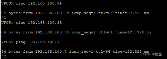
从VM vpc6 ping其它主机,可以通。
适用场景
当DC和WAN是不同的提供商时,可以用这种比较简单的解决方案。
但是由于两个DC属于不同EVPN-VXLAN域,所以 不能支持TYPE2 Mac mobility、ARP suppression。


