记录一下常见的工业协议数据读取方法
目录
- 前言
- Modbus协议说明
- Netty 读取测试
- 使用plc4x 读取测试
- 结束语
前言
Modbus 是一种通讯协议,用于在工业控制系统中进行数据通信和控制。Modbus 协议主要分为两种常用的变体:Modbus RTU 和 Modbus TCP/IP
-
Modbus RTU:Modbus RTU 是一种基于串行通信的协议。
-
Modbus TCP/IP:Modbus TCP/IP 是一种基于 TCP/IP 网络的协议。
本次使用TCP协议,一般常见使用这种协议。
Modbus 协议一般工业设备例如光电信号,各类传感器和执行器等。
一些电力设备(如变压器、开关设备、仪表等)
Modbus协议说明
如果要使用netty读取modbus协议数据必须了解一下协议报文格式。
参考: https://neugates.io/docs/zh/latest/appendix/protocol/modbus_tcp.html
如果设备数量< 30个可以尝试使用 Neuro 产品读取,里面包含配置监控SDK等。
Modbus=MBAP(报文头)+PDU(帧结构)
Netty 读取测试
假设有一个光电IO模块对接了8个激光设备,激光扫描到障碍物为1 没有扫到位0,先通过厂家自带的web端管理界面查看目前的实际信号情况:
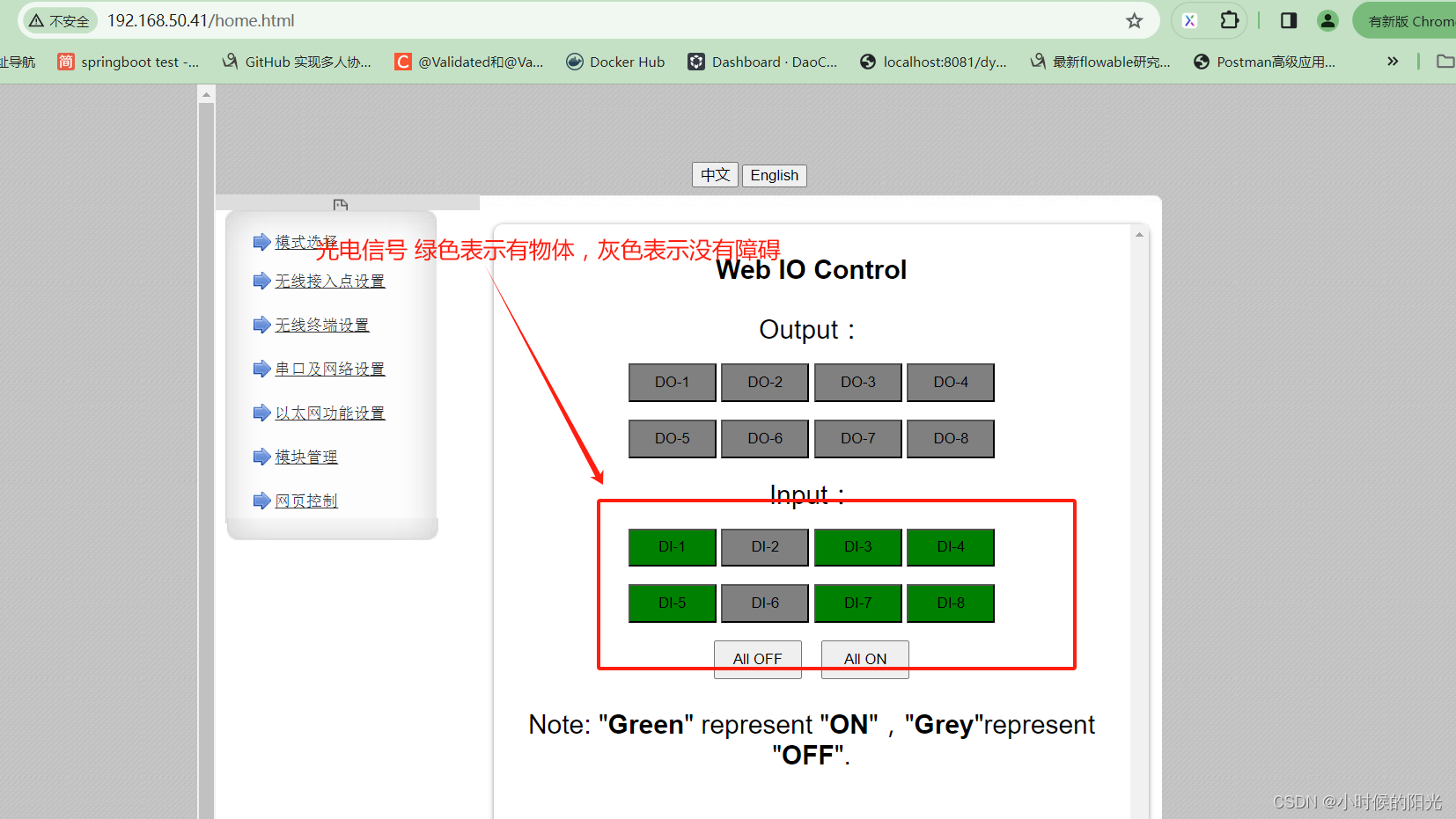
这边测试的Netty代码如下:
package org.example.modbus;

import io.netty.bootstrap.Bootstrap;
import io.netty.buffer.ByteBuf;
import io.netty.buffer.Unpooled;
import io.netty.channel.*;
import io.netty.channel.nio.NioEventLoopGroup;
import io.netty.channel.socket.nio.NioSocketChannel;

public class ModbusClient {

    private final String host;
    private final int port;

    public ModbusClient(String host, int port) {
        this.host = host;
        this.port = port;
    }

    public void start() throws InterruptedException {
        EventLoopGroup group = new NioEventLoopGroup();
        try {
            Bootstrap b = new Bootstrap();
            b.group(group)
                    .channel(NioSocketChannel.class)
                    .option(ChannelOption.SO_KEEPALIVE, true)
                    .handler(new ChannelInitializer<Channel>() {
                        @Override
                        protected void initChannel(Channel ch) {
                            ch.pipeline()
                                    .addLast(new ModbusClientHandler());
                        }
                    });

            ChannelFuture f = b.connect(host, port).sync();
            f.channel().closeFuture().sync();
        } finally {
            group.shutdownGracefully();
        }
    }

    private static class ModbusClientHandler extends ChannelInboundHandlerAdapter {
        @Override
        public void channelActive(ChannelHandlerContext ctx) {
            // writeShort 一次写2个字节   writeByte 一次写1个字节
            ByteBuf buffer = Unpooled.buffer();

            // >>>>>>>>>>>>构造 M B A P Header(报文头)<<<<<<<<<<<<<
            // 事务标识符 占用2个字节
            // 可以解释为报文的序列号,例如测试使用的 Modbus Poll 客户端一直发送数据,
            // 所以每发送一次数据标识符就加一。服务器接收时会把这个数据原封返回。
            buffer.writeShort(1);

            // 协议类型 占用2个字节, 十六进制格式"00 00" 表示Modbus TCP 协议
            buffer.writeShort(0);

            // 长度 占用2个字节, 6 表示报文长度(后面有6个字节),包括 M B A P Header 和 PDU
            // 表示从单元标识符开始后面数据的长度。如:00 06 表示后面有 0X06 个字节长度的数据。
            buffer.writeShort(6);

            // 单元标识符 占用1个字节, 17 表示设备存储单元编号
            buffer.writeByte(17);

            // >>>>>>>>>>>>构造 PDU PDU=功能码+数据<<<<<<<<<<<<<
            // 功能码 占用1个字节, 02 表示读离散量输入
            buffer.writeByte(2);

            // 开始读的数据的地址。从 00 32 开始读数据。
            buffer.writeShort(32);

            // 读取的寄存器数量。从开始位置读 00 08 个寄存器数据。
            buffer.writeShort(8);
            ctx.writeAndFlush(buffer);
        }

        @Override
        public void channelRead(ChannelHandlerContext ctx, Object msg) {
            ByteBuf buffer = (ByteBuf) msg;
            byte[] response = new byte[buffer.readableBytes()];
            buffer.readBytes(response);
            System.out.println("Response: " + bytesToHex(response));
        }

        @Override
        public void exceptionCaught(ChannelHandlerContext ctx, Throwable cause) {
            cause.printStackTrace();
            ctx.close();
        }
    }

    private static String bytesToHex(byte[] bytes) {
        // 这个 bytesToHex 方法用于将一个 byte 数组转换为十六进制格式的字符串。
        // 每个字节被转换为两个十六进制字符,并用空格分隔,
        // 最终返回一个表示十六进制表示形式的字符串
        StringBuilder sb = new StringBuilder();
        for (byte b : bytes) {
            sb.append(String.format("%02X ", b));
        }
        return sb.toString();
    }

    public static void main(String[] args) throws InterruptedException {
        String host = "192.168.50.41";
        int port = 28899;
        new ModbusClient(host, port).start();
    }
}
光电IO设备模块IP地址为 192.168.50.41 端口使用 28899,上面代码是使用netty 向IO模块发送读取 8个光电的离散量信号报文,地址从32开始,然后获得modbus协议的结果报文,最终获得的结果报文解析成十六进制的字符串形式如下:
Response: 00 01 00 00 00 04 11 02 01 CD
还是建议参考上面推荐的文档,这里截取主要信息:
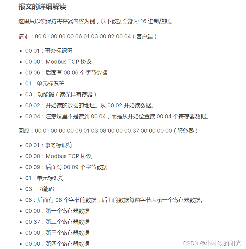
根据上面的样例说明,我们其实想要得到的结果是最后2位16进制数据 DD,占据1个字节,因为我们读取的是离散值(类似true或fase 一般是1或者0),因此我们将 CD转换为二进制数据:
1 1 0 1 1 1 0 1
从低位开始(从右 至 左) 对应厂家web管理界面中的 DI-1 DI-2 …
绿色=1 灰色=0

可以发现netty读取到的信号和厂家web管理界面显示的数据一致。
使用plc4x 读取测试
apache旗下工业协议适配工具库,具体文档查看官网:
链接: https://plc4x.apache.org/users/protocols/modbus.html
pom.xml文件引入maven依赖包:
    <properties>
        <plc4x.version>0.12.0</plc4x.version>
    </properties>

	 <dependency>
		<groupId>org.apache.plc4x</groupId>
		<artifactId>plc4j-api</artifactId>
		<version>${plc4x.version}</version>
	</dependency>

	<dependency>
		<groupId>org.apache.plc4x</groupId>
		<artifactId>plc4j-driver-modbus</artifactId>
		<version>${plc4x.version}</version>
	</dependency>
代码如下:
package cn.guzt.modbustest;

import cn.hutool.core.util.ArrayUtil;
import cn.hutool.core.util.StrUtil;
import org.apache.plc4x.java.api.PlcConnection;
import org.apache.plc4x.java.api.PlcDriverManager;
import org.apache.plc4x.java.api.messages.PlcReadRequest;
import org.apache.plc4x.java.api.messages.PlcReadResponse;
import org.slf4j.Logger;
import org.slf4j.LoggerFactory;

/**
 * apache PLX modbus测试用例
 *
 * @author guzt
 */
public class ModbusExample {

    protected static final Logger logger = LoggerFactory.getLogger(ModbusExample.class);

    public static void main(String[] args) {
        String ip = "192.168.50.41";
        String port = "28899";
        // 单元标识符:相当于设备的地址
        String unitIdentifier = "17";
        String timeout = "5000";
        String urlFormat = "modbus-tcp:tcp://{}:{}?unit-identifier={}&request-timeout={}";

        // try里面会自动关闭连接
        try (PlcConnection plcConnection = PlcDriverManager
                .getDefault()
                .getConnectionManager()
                .getConnection(StrUtil.format(urlFormat, ip, port, unitIdentifier, timeout))) {
            // Check if this connection support reading of data.
            if (!plcConnection.getMetadata().isReadSupported()) {
                logger.info(">>>>>>>>>>>>>>This connection doesn't support reading.");
                return;
            }
            // Check if this connection support writing of data.
            if (!plcConnection.getMetadata().isWriteSupported()) {
                logger.info(">>>>>>>>>>>>>>This connection doesn't support writing.");
                return;
            }

            if (plcConnection.isConnected()) {
                logger.info(">>>>>>>>>>>>>>Modbus已经连上..............");
            }
            // Create a new read request:
            // You will need to pass the reference you are asking for
            PlcReadRequest.Builder builder = plcConnection.readRequestBuilder();
            // 一次性读取几个寄存器里面的内容
            int count = 8;
            // 这里面的起始地址为实际为 32,传递参数时候加1
            int startAddress = 33;
            for (int i = 0; i < count; i++) {
                // 功能码 (tagAddress) Modbus 的操作对象有四种:线圈、离散输入、输入寄存器、保持寄存器。
                // 1. 线圈:相当于开关,在 Modbus 中可读可写,数据只有 00 和 01。
                // 2. 离散量:输入位,开关量,在 Modbus 中只读。
                // 3. 输入寄存器:只能从模拟量输入端改变的寄存器,在 Modbus 中只读。
                // 4. 保持寄存器:用于输出模拟量信号的寄存器,在 Modbus 中可读可写。
                // 查看参考:https://neugates.io/docs/zh/latest/appendix/protocol/modbus_tcp.html
                // 不同功能码对应不同的地址格式:参看 org.apache.plc4x.java.modbus.base.tag.ModbusTagHandler
                builder.addTagAddress("第" + (i + 1) + "个光电信号:", "discrete-input:" + (startAddress + i));
            }

            // 这种方式一次性读取8个:builder.addTagAddress("DI-count8N", "discrete-input:33:BOOL[8]")
            PlcReadRequest readRequest = builder.build();
            logger.info(">>>>>>>>>>>>>>开始读取");

            // Execute the request
            PlcReadResponse response = readRequest.execute().get();
            // Handle the response
            // 创建了一个写请求,尝试将地址1的线圈设置为true
            for (String fieldName : response.getTagNames()) {
                if (response.getObject(fieldName) instanceof Boolean) {
                    logger.info(">>>>>>>>>>>>>>Boolean[" + fieldName + "]: " + response.getBoolean(fieldName));
                } else if (ArrayUtil.isArray(response.getObject(fieldName))) {
                    logger.info(">>>>>>>>>>>>>>Array[" + fieldName + "]: " + response.getObject(fieldName));
                } else {
                    logger.info(">>>>>>>>>>>>>>Object[" + fieldName + "]: " + response.getObject(fieldName));
                }
            }
        } catch (Exception e) {
            e.printStackTrace();
        }
    }
}
执行打印结果如下:
...
16:20:25.378 [main] INFO cn.guzt.modbustest.ModbusExample - >>>>>>>>>>>>>>Boolean[第1个光电信号:]: true
16:20:25.378 [main] INFO cn.guzt.modbustest.ModbusExample - >>>>>>>>>>>>>>Boolean[第2个光电信号:]: false
16:20:25.378 [main] INFO cn.guzt.modbustest.ModbusExample - >>>>>>>>>>>>>>Boolean[第3个光电信号:]: true
16:20:25.378 [main] INFO cn.guzt.modbustest.ModbusExample - >>>>>>>>>>>>>>Boolean[第4个光电信号:]: true
16:20:25.378 [main] INFO cn.guzt.modbustest.ModbusExample - >>>>>>>>>>>>>>Boolean[第5个光电信号:]: true
16:20:25.378 [main] INFO cn.guzt.modbustest.ModbusExample - >>>>>>>>>>>>>>Boolean[第6个光电信号:]: false
16:20:25.378 [main] INFO cn.guzt.modbustest.ModbusExample - >>>>>>>>>>>>>>Boolean[第7个光电信号:]: true
16:20:25.378 [main] INFO cn.guzt.modbustest.ModbusExample - >>>>>>>>>>>>>>Boolean[第8个光电信号:]: true

...
从第1行至第8行记录值 对应厂家web管理界面中的 DI-1 DI-2 …
绿色=true 灰色=fase

可以发现plc4x读取到的信号和厂家web管理界面显示的数据一致。
结束语
读取Modbus的开源库有很多,这里列举常见的使用库,尤其是 Plc4x 这个适配了主流的工业协议,值得我们去研究。
使用netty的话对基本功要求比较高,如果对modbus工业协议包括TCP/IP协议一知半解估计应该是写不出成功案例。



![[游戏开发][UE5]引擎使用学习记录](https://img-blog.csdnimg.cn/direct/22cc94a396ad49b090ed5a0730463252.png)


