The Standard OCC
标准OCC为快速捕获提供快速时钟,为换档和慢速捕获提供慢速时钟。扫描可编程移位寄存器允许ATPG根据需要抑制或脉冲时钟周期。标准OCC的一种用法是用于pattern重定目标的Intest模式。
标准OCC执行所有三个OCC功能:时钟选择、时钟斩波控制和时钟门控。图17-2显示了标准OCC实施。
标准OCC是推荐用于分层核心的OCC。
Design Placement
OCC的插入应确保OCC的快速时钟输入由功能时钟源(通常为PLL)驱动。理想情况下,OCC放置在时钟源(PLL)附近,但应放置在内核内部,以允许pattern重定流所需的本地时钟控制。OCC使用顶级慢速时钟进行换档和慢速捕获,并使用测试pattern信号确定是否向设计提供了测试或功能时钟。
没有理由在功能模式的OCC之后添加时钟多路复用器,因为fast_clock在测试模式信号被取消断言时传播。此外,在功能模式和测试模式下具有快速时钟的公共路径简化了时钟树合成和时序关闭。时钟控制设计用于在功能和测试模式下提供时钟。在功能模式下,快速时钟传递给设计。在测试模式下,快速时钟用于全速捕获,而顶级慢速时钟将用于移位和慢速捕获。提供给PLL的参考时钟是自由运行时钟,通常总是脉冲。建议不要在布局期间flatten时钟控制块,以便于定义时钟门控逻辑及其操作的自动化。
Standard OCC Schematic
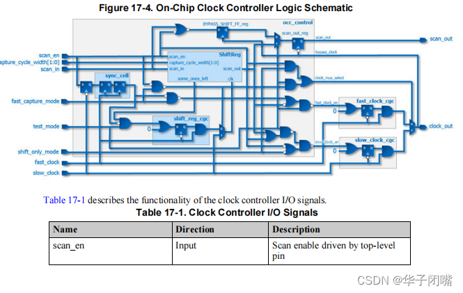
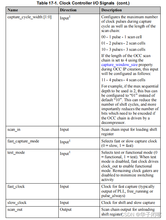
芯片上时钟控制电路的示意图如图所示。
所示示意图表示在没有IJTAG接口的情况下生成的OCC。
Slow Clock Driving Sequential Elements
用于移位和慢速捕获的顶级慢速时钟不能直接控制任何顺序元素,因为慢速时钟在快速捕获模式期间充当捕获的触发器。
在快速捕获期间,工具不会模拟必要的慢速时钟脉冲,这可能导致模拟失配。
Scan Enable Synchronization
为了使顶级扫描使能信号与快速时钟(PLL输出)同步,使用双触发同步单元并由快速时钟计时。这很重要,因为扫描使能被用作将时钟选通到移位寄存器的触发信号。同步单元的输出产生扫描使能信号,该信号与快速时钟同步。
此外,在同步单元的输入侧使用触发器,并由慢时钟的后沿计时。由于scan enable通常扇出到整个电路,并且可能在快时钟之后到达,所以慢时钟上的触发器确保scan enable不会被快时钟同步,直到慢时钟被脉冲化,从而降低竞争条件的风险。为了确保正确的DRC分析和仿真,由同步逻辑驱动的时钟门控单元的输出被定义为捕获内部时钟中的脉冲。当使用TCD流生成pattern时,工具自动将内部时钟定义为捕获时钟中的脉冲。这确保了在load_unload期间正确模拟逻辑,并避免了不必要的DRC冲突。图17-4中所示的同步单元(sync_cell)有一个异步复位端口,如果该端口处于高活动状态,则由scan_en驱动。如果同步单元的复位端口处于低激活状态,则由~scan_en驱动。在RTL描述中,同步单元被描述为一个单独的模块,以便它可以被来自适当库的特定于技术的同步单元替换。
Slow Clock Pulses in Capture
考虑到慢时钟在被快时钟同步之前用于捕获scan enable,它不能直接驱动可能影响扫描操作的任何顺序元件。这是因为假设慢时钟和快时钟不同步,因此在用于快速捕获的external_capture过程中定义了捕获开始时慢时钟上的脉冲:
procedure external_capture ext_fast_cap_proc =
timeplate tmp1 ;
cycle =
force_pi ;
pulse slow_clock;
end;
end;
该工具在计算pattern中的预期值时,不会模拟external_capture过程中定义的时钟脉冲。在ATPG之后,将本程序中定义的时钟脉冲添加到创建的图案中,以确保在快速捕获模式下正确操作。由于时钟门控逻辑的输出被定义为捕获内部时钟中的脉冲,因此该工具不需要模拟首先捕获扫描使能的寄存器上的时钟脉冲。然而,如果慢时钟控制任何其他时序元件,则可能导致模拟失配。
Handling Slow Scan Enable Transitions
根据慢时钟和快时钟的频率的关系,可能需要在快捕获脉冲之前添加更多延迟,以便允许扫描有足够的时间稳定到0。类似地,可能需要在捕获之后和下一个加载/卸载操作之前延迟扫描使能从0到1的转换。这需要将额外的周期添加到external_capture过程中,如下例所示:
procedure external_capture ext_fast_cap_proc =
timeplate tmp1 ;
cycle =
force_pi ;
end;
cycle =
end;
cycle =
end;
cycle =
pulse slow_clock;
end;
cycle =
end;
cycle =
end;
end
在脉冲slow_clock的周期之前添加没有slow_clock脉冲的external_capture周期,延迟快速时钟脉冲,以给scan enable足够的时间过渡到0。slow_clock上的脉冲后的空周期,延迟加载/卸载操作,以使scan enable有足够的时间过渡到1。
Fast Clock With Slower Frequency Than Slow Clock
如果快时钟的频率比慢时钟的频率慢,则需要使用两个不同的timeplate进行移位和加载卸载。大多数情况下,您都可以使用相同的timeplate。
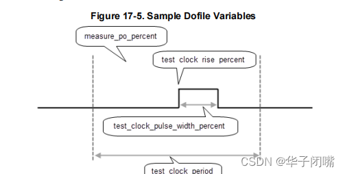
在这种情况下,程序需要使用(较慢)快速时钟周期的额外周期,并且必须在dofile中指定额外的后换档周期,以确保并联测试台的正确操作。有关此设置的示例,请参阅以下文件。采样dofile的变量设置仅为示例值;这些设置是特定于设计的,并包含在此处以供参考。该图说明了如何使用这些变量:
Sample Dofile
## <Read in and set up the design>
…
########## variable settings ############
set test_clock_period 40
set scan_en_mcp 3
set slowest_fast_clock_period 45
set measure_po_percent 45
set test_clock_rise_percent 50
set_test_clock_pulse_width_percent 25
import_scan_mode int_mode -fast_capture_mode on
set_current_mode int_mode_fast
source ../data/
import_procedures.tcl
…
set_fault_type transition
set_external_capture_options -pll_cycles
$pll_cycles
ltest_capture_cycle
set_atpg_limit -pattern_count 128
create_patterns
write_tsdb_data -replace
write_patterns corea_[get_current_mode]_serial.v -verilog -serial \
-replace -end 2 -parameter_list [list SIM_TOP_NAME TB]
write_patterns -corea_[get_current_mode]_parallel.v -verilog -replace \
-parameter_list [list SIM_TOP_NAME TB SIM_POST_SHIFT
$SIM_POST_SHIFT
]
…
The
import_procedures.tcl
file computes the timing, pll_cycles, and SIM_POST_SHIFT:
import_procedures.tcl
set test_clock_period_slow [expr $scan_en_mcp * $test_clock_period]
set test_clock_period_shift_cycle $test_clock_period
set measure_po_shift_cycle [expr \
{round(0.01*$measure_po_percent*$test_clock_period)}]
set test_clock_rise_shift_cycle [expr \
{round(0.01*$test_clock_rise_percent*$test_clock_period)}]
set test_clock_width_shift_cycle [expr \
{round(0.01*$test_clock_pulse_width_percent*$test_clock_period)}]
set test_clock_period_capture_cycle $test_clock_period_slow
set measure_po_capture_cycle [expr \
{$test_clock_period_capture_cycle - ($test_clock_period_shift_cycle- \
$measure_po_shift_cycle)}]
set test_clock_rise_capture_cycle [expr \
{$test_clock_period_capture_cycle - ($test_clock_period_shift_cycle- \
$test_clock_rise_shift_cycle)}]
set test_clock_width_capture_cycle $test_clock_width_shift_cycle
if {$scan_en_mcp <= 2} {
set test_clock_period_pre_shift_cycle $test_clock_period_shift_cycle
set measure_po_pre_shift_cycle $measure_po_shift_cycle
set test_clock_rise_pre_shift_cycle $test_clock_rise_shift_cycle
} else {
set test_clock_period_pre_shift_cycle [expr \
{$test_clock_period_capture_cycle - \
$test_clock_period_shift_cycle}]
set measure_po_pre_shift_cycle [expr \
{$test_clock_period_pre_shift_cycle - \
($test_clock_period_shift_cycle-$measure_po_shift_cycle)}]
set test_clock_rise_pre_shift_cycle [expr \
{$test_clock_period_pre_shift_cycle - \
($test_clock_period_shift_cycle-$test_clock_rise_shift_cycle)}]
}
set test_clock_width_pre_shift_cycle $test_clock_width_shift_cycle
set_procfile_name ../data/
procedures.def
set capture_width 4
set pll_cycles 1
if {![info exists slowest_fast_clock_period]} {
display_message -warning "The variable 'slowest_fast_clock_period' is \
not defined. Assuming the fast_clock to slow_clock period \nratio \
is such that 2 fast_clock cycles fits inside one slow_clock cycle. \
If you are not sure, \nspecify the period of the slowest \
fast_clock as it exists at the input of each OCCs."
incr pll_cycles [expr {int(ceil((2+$capture_width) * 0.5))}]
set SIM_POST_SHIFT 1
} else {
incr pll_cycles [expr {int(ceil((2.0+$capture_width) * \
$slowest_fast_clock_period/$test_clock_period_slow))}]
set SIM_POST_SHIFT [expr {int(ceil(2.0*$slowest_fast_clock_period/ \
$test_clock_period) - 1)}]
}
puts "pll_cycles = $pll_cycles"
puts "SIM_POST_SHIFT = $SIM_POST_SHIFT"
This import file uses a procedures DEF file with three different timeplates:
procedures.def
timeplate
ltest_shift_cycle
=
force_pi 0 ;
measure_po $measure_po_shift_cycle ;
pulse_clock $test_clock_rise_shift_cycle $test_clock_width_shift_cycle ;
period $test_clock_period_shift_cycle ;
end;
timeplate
ltest_capture_cycle
=
force_pi 0 ;
measure_po $measure_po_capture_cycle ;
pulse_clock $test_clock_rise_capture_cycle \
$test_clock_width_capture_cycle ;
period $test_clock_period_capture_cycle ;
end;
timeplate
ltest_pre_shift_cycle
=
force_pi 0 ;
measure_po $measure_po_pre_shift_cycle ;
pulse_clock $test_clock_rise_pre_shift_cycle \
$test_clock_width_pre_shift_cycle ;
period $test_clock_period_pre_shift_cycle ;
end;
set default_timeplate
ltest_capture_cycle
;
procedure shift =
scan_group grp1 ;
timeplate
ltest_shift_cycle
;
cycle =
force_sci ;
measure_sco;
end;
end;
procedure load_unload =
scan_group grp1 ;
timeplate ltest_shift_cycle;
cycle =
timeplate
ltest_pre_shift_cycle
;
end;
apply shift 2;
end;
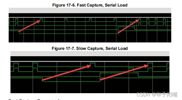
下图显示了此设置的波形图。这些数字从上到下包括以下信号:
•
shift_capture_clock
•
edt_clock
•
edt_update
•
scan_enable


